EP0729802A1 - Bohrer zum Bohren unterschnittener Löcher - Google Patents
Bohrer zum Bohren unterschnittener Löcher Download PDFInfo
- Publication number
- EP0729802A1 EP0729802A1 EP96301327A EP96301327A EP0729802A1 EP 0729802 A1 EP0729802 A1 EP 0729802A1 EP 96301327 A EP96301327 A EP 96301327A EP 96301327 A EP96301327 A EP 96301327A EP 0729802 A1 EP0729802 A1 EP 0729802A1
- Authority
- EP
- European Patent Office
- Prior art keywords
- undercut
- drill bit
- hole
- cylindrical sleeve
- contact portion
- Prior art date
- Legal status (The legal status is an assumption and is not a legal conclusion. Google has not performed a legal analysis and makes no representation as to the accuracy of the status listed.)
- Granted
Links
Images


Classifications
-
- B—PERFORMING OPERATIONS; TRANSPORTING
- B23—MACHINE TOOLS; METAL-WORKING NOT OTHERWISE PROVIDED FOR
- B23B—TURNING; BORING
- B23B51/00—Tools for drilling machines
- B23B51/0018—Drills for enlarging a hole
- B23B51/0045—Drills for enlarging a hole by expanding or tilting the toolhead
-
- Y—GENERAL TAGGING OF NEW TECHNOLOGICAL DEVELOPMENTS; GENERAL TAGGING OF CROSS-SECTIONAL TECHNOLOGIES SPANNING OVER SEVERAL SECTIONS OF THE IPC; TECHNICAL SUBJECTS COVERED BY FORMER USPC CROSS-REFERENCE ART COLLECTIONS [XRACs] AND DIGESTS
- Y10—TECHNICAL SUBJECTS COVERED BY FORMER USPC
- Y10T—TECHNICAL SUBJECTS COVERED BY FORMER US CLASSIFICATION
- Y10T408/00—Cutting by use of rotating axially moving tool
- Y10T408/83—Tool-support with means to move Tool relative to tool-support
- Y10T408/85—Tool-support with means to move Tool relative to tool-support to move radially
- Y10T408/858—Moving means including wedge, screw or cam
- Y10T408/8583—Moving means including wedge, screw or cam with resiliently urged Tool
- Y10T408/85843—Resilient Tool or tool-support
-
- Y—GENERAL TAGGING OF NEW TECHNOLOGICAL DEVELOPMENTS; GENERAL TAGGING OF CROSS-SECTIONAL TECHNOLOGIES SPANNING OVER SEVERAL SECTIONS OF THE IPC; TECHNICAL SUBJECTS COVERED BY FORMER USPC CROSS-REFERENCE ART COLLECTIONS [XRACs] AND DIGESTS
- Y10—TECHNICAL SUBJECTS COVERED BY FORMER USPC
- Y10T—TECHNICAL SUBJECTS COVERED BY FORMER US CLASSIFICATION
- Y10T408/00—Cutting by use of rotating axially moving tool
- Y10T408/83—Tool-support with means to move Tool relative to tool-support
- Y10T408/85—Tool-support with means to move Tool relative to tool-support to move radially
- Y10T408/858—Moving means including wedge, screw or cam
- Y10T408/8588—Axially slidable moving-means
- Y10T408/85896—Annular wedge-collar
-
- Y—GENERAL TAGGING OF NEW TECHNOLOGICAL DEVELOPMENTS; GENERAL TAGGING OF CROSS-SECTIONAL TECHNOLOGIES SPANNING OVER SEVERAL SECTIONS OF THE IPC; TECHNICAL SUBJECTS COVERED BY FORMER USPC CROSS-REFERENCE ART COLLECTIONS [XRACs] AND DIGESTS
- Y10—TECHNICAL SUBJECTS COVERED BY FORMER USPC
- Y10T—TECHNICAL SUBJECTS COVERED BY FORMER US CLASSIFICATION
- Y10T82/00—Turning
- Y10T82/12—Radially moving rotating tool inside bore
Definitions
- the present invention relates to a drill bit for drilling a hole which drills a hole of a predetermined depth in an object such as concrete and, at the same time, forming an undercut portion (flared portion of hole) made at the bottom of the hole with a greater diameter.
- an anchor bolt in a drilled object such as concrete, there is such a method that a hole of a predetermined depth is drilled in the object, a base portion of the anchor bolt is inserted into the drilled hole and a slitted cylindrical body, fitted on the outer circumference of the anchor bolt, having slits cut in the axial direction is opened to enlarge, thereby to exert frictional resistance with the wall of the hole.
- pull-out resistant strength of the anchor bolt can be greatly increased by cutting the wall of the drilled hole corresponding to the base portion of the embedded bolt to form an undercut portion of greater diameter, in advance.
- the drill bit for drilling an undercut hole of the prior art described above have such a drawback that a hole with the undercut is drilled in two processes, because, first a hole is drilled by using an ordinary drilling tool, and then, the undercut portion is formed at the bottom of the hole by processing the drilled hole (primary hole).
- the present invention aims at solving the problems described above, and has an object of providing a drill bit for drilling an undercut hole which is capable of drilling a hole of a predetermined depth in an object and, at the same time, form an undercut portion at the bottom of the hole in a continuous operation.
- a drill bit for drilling an undercut hole according to claim 1 of the invention for achieving the object described above comprises a body having a shank, a drill bit fixed onto the body, a thrust transmitting member arranged to the body freely movably in the vertical direction having a contact portion which comes into contact with the surface of an object to be drilled, a guide groove cut in the axial direction on the periphery of the drill bit with a sloped surface formed at the lower end thereof, an undercut cutting member provided with an undercut cutting edge at the lower end thereof corresponding to the sloped surface, a pull-up spring installed in linkage with the undercut cutting member, and a working force transmitting mechanism which is installed on the body in linkage with the thrust transmitting member and with the undercut cutting member, to press down the undercut cutting member against the resistance of the pull-up spring by approaching movement of the body and the thrust transmitting member each other and cause the undercut cutting edge to protrude outwardly of the drill bit body surface.
- the thrust transmitting member of claim 1 is constituted of a cylindrical sleeve having a contact portion on the lower end thereof, the lower part of the body is fitted in the opening at the upper end of the cylindrical sleeve, the lock pin provided on the body projecting thereon is engaged with the elongated hole made in the cylindrical sleeve, the pull-up spring is installed between the contact portion of the cylindrical sleeve and a plate engaged with the upper end of the undercut cutting member, a working force transmitting mechanism is constituted by housing a plurality of balls consecutively in an inverse U-shaped hole made in the body to form a train of balls, connecting rods are provided to project downwardly of the body to make contact with both ends of the train of balls, and the lower end of one of the connecting rods is brought into contact with the contact portion of the cylindrical sleeve, while the lower end of the other connecting rod is brought into contact with the plate.
- a drill bit for drilling an undercut hole according to claim 3 is the drill bit for drilling an undercut hole according to claim 2, wherein an undercut marker, having a marking edge on the bottom face of the plate which is engaged with the upper end of the undercut cutting member, is installed to project, a communicating hole is drilled in the contact portion of the cylindrical sleeve corresponding to the undercut marker, and the marking edge is arranged to freely protrude from and retract into the communicating hole downwardly.
- a drill bit for drilling an undercut hole according to claim 4 is the drill bit for drilling an undercut hole according to claim 1, wherein the thrust transmitting member is constituted by forming the contact portion at the lower end of the cylindrical sleeve, the upper end of the cylindrical sleeve is slidably fitted between the oil case attached on the body and a cylinder provided on the body concentrically with the oil case to form a first working oil chamber, the working force transmitting sleeve is slidably fitted between the cylinder and the body of the drill bit to form a second working oil chamber, the second working oil chamber and the first working oil chamber are made communicate with each other via an oil passage hole drilled through the cylinder, and the lower end of the working force transmitting sleeve is engaged with the undercut cutting member to constitute the working force transmitting mechanism.
- a hole is drilled by the drill edge of the drill bit until the contact portion of the thrust transmitting member makes contact with the surface of the object to be drilled.
- the contact portion of the thrust transmitting member makes contact with the surface of the object to be drilled and the downward movement of the thrust transmitting member stops, approaching movement of the body toward the thrust transmitting member presses the undercut cutting member downward against the resistance of the pull-up spring via the working force transmitting mechanism, thereby protruding the undercut cutting edge outwardly of the drill bit surface from the sloped surface of the guide groove and forming an undercut portion at the bottom of the drilled hole.
- the effect of claim 1 is achieved while the contact portion makes contact with the surface of the object to be drilled and the body continues to move down relative to the cylindrical sleeve to the extent allowed by the elongated hole.
- the connecting rod making contact with the contact portion enters in the body to move the train of balls housed in the inverse U-shaped hole, so that the movement of the train of balls presses another connecting rod out of the body downward to press down the undercut cutting member, thereby forming the undercut portion by means of the undercut cutting edge.
- the effect of claim 2 is achieved while, at the time forming of the undercut portion by means of the undercut cutting edge is completed, the plate moves down in the cylindrical sleeve so that the undercut marker passes through the communicating hole drilled in the contact portion of the cylindrical sleeve and the marking edge protrudes below the contact portion to cut a dircular line on the surface of the object to be drilled. It can be confirmed that the undercut portion has been cut, by observing this circular line.
- the effect of claim 1 is achieved while, when the contact portion makes contact with the surface of the object to be drilled and the downward movement of the cylindrical sleeve stops, working oil in the first working oil chamber is pressed at the upper end of the cylindrical sleeve and moves through the oil passage hole to the second working oil chamber, so that the movement of the working oil to the second working oil chamber presses down the working force transmitting sleeve and the undercut cutting member, thereby forming the undercut portion by means of the undercut cutting edge.
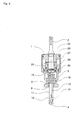
- Fig.1 is a side view of the drill bit according to the first embodiment of the invention as partially cut away.
- numeral 1 denotes a body having a shank 2 which is to be connected to a drive spindle (not shown), provided at the center of the top face thereof and a drill bit 3 fixed at the center of the bottom face thereof.
- a drill edge 4 provided on the bottom of the drill bit 3 is the same as that of a known drilling tool for drilling an ordinary straight hole.
- Numeral 5 denotes a cylindrical sleeve arranged freely movably in the vertical direction relative to the body portion 1, with a contact portion 6 which makes contact with the surface of an object to be drilled being formed at the lower end thereof.
- Lower part of the body 1 is slidably fitted in an upper opening of the cylindrical sleeve 5, a lock pin 8 provided to project on the body portion 1 is engaged in an elongated hole 7 made in the cylindrical sleeve 5 to regulate the range of vertical movement of the body 1 and the cylindrical sleeve 5.
- the lock pin 8 is held in a holding hole 9 made in the body portion 1 and made to project into the elongated hole 7 under the pressure of a spring 10, thereby enabling it to separate the body 1 and the cylindrical sleeve 5 under such a condition that the lock pin 8 is pressed into the holding hole 9 side against the resistance of the spring 10.
- Numeral 11 denotes a guide groove made on the side face of the drill bit 3 by cutting therein in the axial direction, while the guide groove 11 has a sloped surface 12 formed at the bottom thereof to slope outwardly reaching the drill bit 3 surface.
- Numeral 13 denotes an undercut cutting member housed in the guide groove 11 to be freely movable within a predetermined range relative to the drill bit 3, with the lower half of the undercut cutting member 13 being constituted of a blade 14 which has an Appropriate degree of elasticity with an undercut cutting edge 15 being provided at the lower end thereof corresponding to the sloped surface 12 of the guide groove 11, and a support portion 16 being provided at the upper end of the undercut cutting member 13 projecting outward.
- Numeral 17 denotes a plate provided in the cylindrical sleeve 5 and engaged with the support portion 16 of the undercut cutting member 13, with a pull-up spring 18 being arranged between the plate 17 and the contact portion 6 of the cylindrical sleeve 5 so that, under the normal condition, the undercut cutting member 13 is pulled up together with the plate 17 relative to the drill bit 3 to retract the undercut cutting edge 15 into the guide groove 11 and the plate 17 is made contact with the bottom face of the body 1 under the pressure of the pull-up spring 18.
- Numeral 19 denotes an inverse U-shaped hole made in the body 1 with a plurality of balls being housed consecutively in the inverse U-shaped hole 19 to form a train of balls 20, while connecting rods 21, 22 are provided to project downwardly of the body 1 to make contact with both ends of the train of balls 20, with the lower end of one connecting rod 21 being brought into contact with the contact portion 6 of the cylindrical sleeve 5, and the lower end of the other connecting rod 22 being brought into contact with the plate 17, thereby forming the working force transmitting mechanism 23.
- Numeral 24 denotes an undercut marker provided on the bottom face of the plate 17 near the periphery of the plate 17 to project downward, having a marking blade 24a at the lower end.
- a communicating hole 25 is provided in the contact portion 6 of the cylindrical sleeve 5 corresponding to the undercut marker 24 so that, when the plate 17 moves down in the cylindrical sleeve 5, the undercut marker 24 is passed through the communicating hole 25 thereby making the marking edge 24a projected below the contact portion 6.
- Numeral 26 denotes a cover attached on the outer circumference of the body 1, for stabilizing the lock pin 8 and the train of balls 20 in the body 1.
- Fig.2 The drill edge 4 of the drill bit 3 is pressed against the object A to be drilled to drill a drilled hole B.
- the drilled hole B reaches a predetermined depth and the contact portion 6 of the cylindrical sleeve 5 makes contact with the surface of the object to be drilled A.
- Fig.3 After the contact portion 6 of the cylindrical sleeve 5 has made contact with the surface of the object to be drilled A, the body 1 is thrust into the cylindrical sleeve 5 and continues to move down so that drilling of the drilled hole B continues.
- the plate 17 is pressed down together with the undercut cutting member 13 over a greater distance than the downward movement of the body 1 against the resistance of the pull-up spring 18, and the undercut cutting edge 15 moves along the sloped surface 12 of the guide groove 11 to protrude outwardly of the drill bit 3 surface and starts cutting of the drilled hole wall.
- the undercut cutting edge 15 reaches the point of maximum protrusion on the drill bit 3 surface, to complete cutting of the undercut portion C where the wall of the hole is tapered to enlarge the diameter downward.
- the marking edge 24 of the undercut marker 23 protrudes from the communicating hole 25 downwardly of the contact portion 6 and is pressed against the surface of the object to be drilled A, thereby marking a circular line D on the surface of the object to be drilled A. Completion of the undercut portion C cutting process can be confirmed by observing the circular line D.
- the process proceeds in reversed order of the procedure described above; first the pull-up spring 18 pulls up the plate 17 and the undercut cutting member 13 and, at the same time, the cylindrical sleeve 5 returns to the initial position while the undercut cutting edge 15 retracts into the guide groove 11 and the drill edge 3 is pulled out of the drilled hole B to complete the drilling operation.
- the circular line D marked on the surface of the object to be drilled A provides various information even after the drilling operation has been completed.
- existence of the circular line D means that the hole is a drilled hole B with an undercut portion C being cut therein.
- radius of the circular line D is given a relationship with the depth of the drilled hole B or the position of the undercut portion C, it provides convenience in selecting the type of anchor bolt to be planted and other purposes.
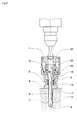
- Fig.4 is a front view of the drill bit according to the second embodiment of the invention as partially cut away.
- movement of the working oil is used to operate the working force transmitting mechanism.
- an oil case 27 is attached to the body 1 with a cylinder 28 being installed suspended on the body 1 concentrically in the oil case 27, the upper end of the cylindrical sleeve 5 being fitted slidably between the oil case 27 and the cylinder 28 to form the first working oil chamber 29 and a working force transmitting sleeve 30 being fitted slidably between a cylindrical portion 28 and the drill bit 3 to form a second working oil chamber 31, while an oil passage hole 32 is provided to penetrate through the upper part of the cylinder 28 so that the first working oil chamber 29 and the second working oil chamber 31 communicate with each other, and the lower end of the working force transmitting sleeve 30 is engaged with the support portion 16 of the undercut cutting member 13 thereby constituting a working force transmitting mechanism 33.
- the drill edge 4 of the drill bit 3 is pressed against the object to be drilled A to drill the drilled hole B and, after the contact portion 6 of the cylindrical sleeve 5 makes contact with the surface of the object to be drilled A, the upper end of the cylindrical sleeve 5 is thrusted into the first working oil chamber 29 to move the working oil from the first working oil chamber 29 via the oil passage hole 32 into the second working oil chamber 31, thereby pressing down the working force transmitting sleeve 30.
- an undercut portion can be formed smoothly and surely because, after the thrust transmitting member has made contact with the surface of the object to be drilled, movement of forcing the body downward relative to the thrust transmitting member is converted to the press-down movement of the undercut portion cutting member to increase the distance of pressing down the undercut cutting member, thereby causing the undercut blade to protrude outwardly of the drill bit surface.
- An undercut hole can be drilled easily and efficiently in an operating procedure substantially the same as that of the conventional straight hole drilling operation, because drilling of a drilled hole of a predetermined depth as a primary hole for planting an anchor bolt and forming of an undercut portion at the bottom of the drilled hole can be carried out continuously in a single process.
- Figure 1 is a side view of the drill bit according to the first embodiment of the invention as partially cut away.
- Figure 2 is a sectional view to explain the drilling procedure by means of the drill bit of the invention.
- Figure 3 is a sectional view to explain the drilling procedure by means of the drill bit of the invention.
- Figure 1 is a front view of the drill bit according to the second embodiment of the invention as partially cut away.
- Figure 5 is a sectional view to explain the drilling procedure by means of the drill bit of the invention.
Landscapes
- Engineering & Computer Science (AREA)
- Mechanical Engineering (AREA)
- Processing Of Stones Or Stones Resemblance Materials (AREA)
Applications Claiming Priority (3)
| Application Number | Priority Date | Filing Date | Title |
|---|---|---|---|
| JP40131/95 | 1995-02-28 | ||
| JP4013195 | 1995-02-28 | ||
| JP7040131A JP2862807B2 (ja) | 1995-02-28 | 1995-02-28 | アンダーカット部付き孔の穿孔装置 |
Publications (2)
| Publication Number | Publication Date |
|---|---|
| EP0729802A1 true EP0729802A1 (de) | 1996-09-04 |
| EP0729802B1 EP0729802B1 (de) | 2000-04-19 |
Family
ID=12572260
Family Applications (1)
| Application Number | Title | Priority Date | Filing Date |
|---|---|---|---|
| EP96301327A Expired - Lifetime EP0729802B1 (de) | 1995-02-28 | 1996-02-27 | Bohrer zum Bohren unterschnittener Löcher |
Country Status (5)
| Country | Link |
|---|---|
| US (1) | US5735650A (de) |
| EP (1) | EP0729802B1 (de) |
| JP (1) | JP2862807B2 (de) |
| AU (1) | AU698900B2 (de) |
| DE (1) | DE69607776T2 (de) |
Cited By (2)
| Publication number | Priority date | Publication date | Assignee | Title |
|---|---|---|---|---|
| EP0795368A3 (de) * | 1996-03-13 | 1998-04-08 | Kabushiki Kaisha Miyanaga | Gerät zum Bohren eines Loches mit Hinterschnitt |
| US5810523A (en) * | 1995-02-28 | 1998-09-22 | Kabushiki Kaisha Miyanaga | Apparatus for drilling a hole having an undercut space |
Families Citing this family (10)
| Publication number | Priority date | Publication date | Assignee | Title |
|---|---|---|---|---|
| AUPN674795A0 (en) * | 1995-11-23 | 1995-12-14 | Ramset Fasteners (Aust.) Pty. Limited | Undercutting drills |
| US5885294A (en) * | 1997-09-22 | 1999-03-23 | Ethicon, Inc. | Apparatus and method for anchoring a cord-like element to a workpiece |
| US6761516B2 (en) * | 2002-10-11 | 2004-07-13 | The Boeing Company | Method for generating holes in laminate materials |
| US20040149093A1 (en) * | 2003-01-30 | 2004-08-05 | Gordon Tang | Tool for forming an undercut hole and method for its use |
| CN1931550B (zh) * | 2006-10-11 | 2010-12-22 | 赖其淡 | 具有钻扩孔功能的钻头 |
| US8211182B2 (en) * | 2007-09-17 | 2012-07-03 | Linares Medical Devices, Llc | Hip socket with assembleable male ball shape having integrally formed ligament and female receiver and installation kit |
| JP5806782B2 (ja) | 2013-08-23 | 2015-11-10 | 株式会社ミヤナガ | 拡径孔部付き孔の穿孔装置 |
| DE102014003721A1 (de) * | 2014-03-18 | 2015-09-24 | Karl Storz Gmbh & Co. Kg | Werkzeug und Verfahren zum Erzeugen eines Hinterschnitts in einem Knochen |
| CN109570578B (zh) * | 2019-01-03 | 2020-12-04 | 上海友升铝业有限公司 | 一种可缩进式cnc加工用沉头刀具 |
| CN118977981B (zh) * | 2024-09-25 | 2025-12-16 | 湖北中烟工业有限责任公司 | 一种皮带输送机防积垢托辊 |
Citations (7)
| Publication number | Priority date | Publication date | Assignee | Title |
|---|---|---|---|---|
| US1536208A (en) * | 1925-01-14 | 1925-05-05 | George Hugh Foster | Expansible boring tool |
| GB518688A (en) * | 1938-09-02 | 1940-03-05 | Shawlock Inc | Improvements in or relating to a boring tool, particularly for boring taper holes |
| DE2148654A1 (de) * | 1970-09-30 | 1972-04-06 | Buck James Russel | Hydraulisch betaetigte Werkzeugspannvorrichtung |
| US4402642A (en) * | 1981-01-12 | 1983-09-06 | Universal Automatic Corporation | Machine tool bar feed |
| US4462726A (en) * | 1981-06-08 | 1984-07-31 | Irontite Products Co., Inc. | Apparatus for forming a groove |
| GB2157207A (en) * | 1984-03-08 | 1985-10-23 | Miyanaga Kk | Undercutting drill |
| EP0395335A1 (de) * | 1989-04-24 | 1990-10-31 | Kabushiki Kaisha Miyanaga | Meissel zum Bohren eines hinterschnittenen Loches |
Family Cites Families (13)
| Publication number | Priority date | Publication date | Assignee | Title |
|---|---|---|---|---|
| GB1184106A (en) * | 1967-04-18 | 1970-03-11 | John Darbyshire & Company Ltd | Improvements in or relating to Reamers |
| US3696454A (en) * | 1970-09-10 | 1972-10-10 | Teledyne Inc | Thread cutting die head |
| JPS5850855B2 (ja) * | 1978-06-07 | 1983-11-12 | ヒルティ・アクチエンゲゼルシャフト | 穿孔機 |
| US4354559A (en) * | 1980-07-30 | 1982-10-19 | Tri-State Oil Tool Industries, Inc. | Enlarged borehole drilling method and apparatus |
| JPS60172408A (ja) * | 1984-02-17 | 1985-09-05 | Miyanaga:Kk | アンダ−カツト穿孔用打撃穿孔装置 |
| JPS60145005U (ja) * | 1984-03-08 | 1985-09-26 | 株式会社ミヤナガ | 拡径孔部削成装置 |
| JPH0110173Y2 (de) * | 1984-09-07 | 1989-03-23 | ||
| JPH0239688Y2 (de) * | 1986-06-10 | 1990-10-24 | ||
| JPH0829445B2 (ja) * | 1986-12-16 | 1996-03-27 | 株式会社ミヤナガ | 上向き拡径孔部削成装置 |
| DE3839617A1 (de) * | 1988-11-24 | 1990-05-31 | Fischer Artur Werke Gmbh | Vorrichtung zur herstellung einer hinterschneidung in einem bohrloch |
| JPH0411766Y2 (de) * | 1989-03-08 | 1992-03-24 | ||
| DE4014224A1 (de) * | 1990-05-04 | 1991-11-07 | Fischer Artur Werke Gmbh | Vorrichtung zur herstellung von bohrloechern mit hinterschneidung |
| FR2679293B1 (fr) * | 1991-07-16 | 1999-01-22 | Inst Francais Du Petrole | Dispositif d'actionnement associe a une garniture de forage et comportant un circuit hydrostatique en fluide de forage, methode d'actionnement et leur application. |
-
1995
- 1995-02-28 JP JP7040131A patent/JP2862807B2/ja not_active Expired - Fee Related
-
1996
- 1996-01-17 US US08/587,395 patent/US5735650A/en not_active Expired - Lifetime
- 1996-02-12 AU AU44460/96A patent/AU698900B2/en not_active Ceased
- 1996-02-27 DE DE69607776T patent/DE69607776T2/de not_active Expired - Fee Related
- 1996-02-27 EP EP96301327A patent/EP0729802B1/de not_active Expired - Lifetime
Patent Citations (7)
| Publication number | Priority date | Publication date | Assignee | Title |
|---|---|---|---|---|
| US1536208A (en) * | 1925-01-14 | 1925-05-05 | George Hugh Foster | Expansible boring tool |
| GB518688A (en) * | 1938-09-02 | 1940-03-05 | Shawlock Inc | Improvements in or relating to a boring tool, particularly for boring taper holes |
| DE2148654A1 (de) * | 1970-09-30 | 1972-04-06 | Buck James Russel | Hydraulisch betaetigte Werkzeugspannvorrichtung |
| US4402642A (en) * | 1981-01-12 | 1983-09-06 | Universal Automatic Corporation | Machine tool bar feed |
| US4462726A (en) * | 1981-06-08 | 1984-07-31 | Irontite Products Co., Inc. | Apparatus for forming a groove |
| GB2157207A (en) * | 1984-03-08 | 1985-10-23 | Miyanaga Kk | Undercutting drill |
| EP0395335A1 (de) * | 1989-04-24 | 1990-10-31 | Kabushiki Kaisha Miyanaga | Meissel zum Bohren eines hinterschnittenen Loches |
Cited By (2)
| Publication number | Priority date | Publication date | Assignee | Title |
|---|---|---|---|---|
| US5810523A (en) * | 1995-02-28 | 1998-09-22 | Kabushiki Kaisha Miyanaga | Apparatus for drilling a hole having an undercut space |
| EP0795368A3 (de) * | 1996-03-13 | 1998-04-08 | Kabushiki Kaisha Miyanaga | Gerät zum Bohren eines Loches mit Hinterschnitt |
Also Published As
| Publication number | Publication date |
|---|---|
| US5735650A (en) | 1998-04-07 |
| AU4446096A (en) | 1996-09-05 |
| EP0729802B1 (de) | 2000-04-19 |
| JPH08229931A (ja) | 1996-09-10 |
| DE69607776T2 (de) | 2000-11-23 |
| DE69607776D1 (de) | 2000-05-25 |
| JP2862807B2 (ja) | 1999-03-03 |
| AU698900B2 (en) | 1998-11-12 |
Similar Documents
| Publication | Publication Date | Title |
|---|---|---|
| EP0729802A1 (de) | Bohrer zum Bohren unterschnittener Löcher | |
| CA1157464A (en) | Bore undercutting tool | |
| US4998981A (en) | Bit for drilling an undercut hole | |
| US4787848A (en) | Method and apparatus for drilling bores in jaw bone tissue for the reception of dental anchors | |
| EP0395620A3 (de) | Kernbohrwerkzeug | |
| EP0567254B1 (de) | Betonanker | |
| HK1006291B (en) | Bit for drilling an undercut hole | |
| US4202557A (en) | Drilling device | |
| US4444279A (en) | Drilling tool | |
| JPH02162005A (ja) | アンダカツト部を有する穿孔を製作するための穿孔装置 | |
| SU651674A3 (ru) | Сверлильна головка | |
| EP0302202A2 (de) | Vorrichtung zum Festsetzen von Befestigungselementen | |
| US4279315A (en) | Apparatus for extracting cores | |
| US5810523A (en) | Apparatus for drilling a hole having an undercut space | |
| JPH03107607A (ja) | 拡開アンカーの下穴アンダーカット装置 | |
| JP2677948B2 (ja) | コアドリル | |
| JP2862830B2 (ja) | アンダーカット部付き孔の穿孔装置 | |
| GB2053042A (en) | Drilling tool | |
| JPH0110174Y2 (de) | ||
| US2896212A (en) | Chuck and handle for manual installation of self-drilling expansion shells | |
| SU898041A1 (ru) | Скважинна труболовка | |
| EP0425802B1 (de) | Bohrvorrichtung mit einem Schlagdrehwerkzeug | |
| SU1317086A1 (ru) | Рабочий орган дл проходки скважин | |
| JPH0236651Y2 (de) | ||
| SU1641994A2 (ru) | Устройство дл нарезани щелей на стенках скважин |
Legal Events
| Date | Code | Title | Description |
|---|---|---|---|
| PUAI | Public reference made under article 153(3) epc to a published international application that has entered the european phase |
Free format text: ORIGINAL CODE: 0009012 |
|
| AK | Designated contracting states |
Kind code of ref document: A1 Designated state(s): DE FR GB |
|
| 17P | Request for examination filed |
Effective date: 19960930 |
|
| 17Q | First examination report despatched |
Effective date: 19971006 |
|
| GRAG | Despatch of communication of intention to grant |
Free format text: ORIGINAL CODE: EPIDOS AGRA |
|
| GRAG | Despatch of communication of intention to grant |
Free format text: ORIGINAL CODE: EPIDOS AGRA |
|
| GRAH | Despatch of communication of intention to grant a patent |
Free format text: ORIGINAL CODE: EPIDOS IGRA |
|
| GRAH | Despatch of communication of intention to grant a patent |
Free format text: ORIGINAL CODE: EPIDOS IGRA |
|
| GRAA | (expected) grant |
Free format text: ORIGINAL CODE: 0009210 |
|
| AK | Designated contracting states |
Kind code of ref document: B1 Designated state(s): DE FR GB |
|
| REF | Corresponds to: |
Ref document number: 69607776 Country of ref document: DE Date of ref document: 20000525 |
|
| ET | Fr: translation filed | ||
| PLBE | No opposition filed within time limit |
Free format text: ORIGINAL CODE: 0009261 |
|
| STAA | Information on the status of an ep patent application or granted ep patent |
Free format text: STATUS: NO OPPOSITION FILED WITHIN TIME LIMIT |
|
| 26N | No opposition filed | ||
| REG | Reference to a national code |
Ref country code: GB Ref legal event code: IF02 |
|
| PGFP | Annual fee paid to national office [announced via postgrant information from national office to epo] |
Ref country code: DE Payment date: 20090219 Year of fee payment: 14 |
|
| PGFP | Annual fee paid to national office [announced via postgrant information from national office to epo] |
Ref country code: GB Payment date: 20090225 Year of fee payment: 14 |
|
| PGFP | Annual fee paid to national office [announced via postgrant information from national office to epo] |
Ref country code: FR Payment date: 20090213 Year of fee payment: 14 |
|
| GBPC | Gb: european patent ceased through non-payment of renewal fee |
Effective date: 20100227 |
|
| REG | Reference to a national code |
Ref country code: FR Ref legal event code: ST Effective date: 20101029 |
|
| PG25 | Lapsed in a contracting state [announced via postgrant information from national office to epo] |
Ref country code: FR Free format text: LAPSE BECAUSE OF NON-PAYMENT OF DUE FEES Effective date: 20100301 |
|
| PG25 | Lapsed in a contracting state [announced via postgrant information from national office to epo] |
Ref country code: DE Free format text: LAPSE BECAUSE OF NON-PAYMENT OF DUE FEES Effective date: 20100901 |
|
| PG25 | Lapsed in a contracting state [announced via postgrant information from national office to epo] |
Ref country code: GB Free format text: LAPSE BECAUSE OF NON-PAYMENT OF DUE FEES Effective date: 20100227 |