EP0729802B1 - Foret pour le perçage de trous chambrés - Google Patents
Foret pour le perçage de trous chambrés Download PDFInfo
- Publication number
- EP0729802B1 EP0729802B1 EP96301327A EP96301327A EP0729802B1 EP 0729802 B1 EP0729802 B1 EP 0729802B1 EP 96301327 A EP96301327 A EP 96301327A EP 96301327 A EP96301327 A EP 96301327A EP 0729802 B1 EP0729802 B1 EP 0729802B1
- Authority
- EP
- European Patent Office
- Prior art keywords
- undercut
- drill bit
- cutting member
- cylindrical sleeve
- hole
- Prior art date
- Legal status (The legal status is an assumption and is not a legal conclusion. Google has not performed a legal analysis and makes no representation as to the accuracy of the status listed.)
- Expired - Lifetime
Links
- 238000005553 drilling Methods 0.000 title claims description 25
- 238000005520 cutting process Methods 0.000 claims description 62
- 239000003550 marker Substances 0.000 claims description 9
- 239000007787 solid Substances 0.000 claims description 5
- 238000000034 method Methods 0.000 description 5
- 208000019901 Anxiety disease Diseases 0.000 description 1
- 230000036506 anxiety Effects 0.000 description 1
- 230000001419 dependent effect Effects 0.000 description 1
- 230000000694 effects Effects 0.000 description 1
- 238000011017 operating method Methods 0.000 description 1
- 230000000087 stabilizing effect Effects 0.000 description 1
Images


Classifications
-
- B—PERFORMING OPERATIONS; TRANSPORTING
- B23—MACHINE TOOLS; METAL-WORKING NOT OTHERWISE PROVIDED FOR
- B23B—TURNING; BORING
- B23B51/00—Tools for drilling machines
- B23B51/0018—Drills for enlarging a hole
- B23B51/0045—Drills for enlarging a hole by expanding or tilting the toolhead
-
- Y—GENERAL TAGGING OF NEW TECHNOLOGICAL DEVELOPMENTS; GENERAL TAGGING OF CROSS-SECTIONAL TECHNOLOGIES SPANNING OVER SEVERAL SECTIONS OF THE IPC; TECHNICAL SUBJECTS COVERED BY FORMER USPC CROSS-REFERENCE ART COLLECTIONS [XRACs] AND DIGESTS
- Y10—TECHNICAL SUBJECTS COVERED BY FORMER USPC
- Y10T—TECHNICAL SUBJECTS COVERED BY FORMER US CLASSIFICATION
- Y10T408/00—Cutting by use of rotating axially moving tool
- Y10T408/83—Tool-support with means to move Tool relative to tool-support
- Y10T408/85—Tool-support with means to move Tool relative to tool-support to move radially
- Y10T408/858—Moving means including wedge, screw or cam
- Y10T408/8583—Moving means including wedge, screw or cam with resiliently urged Tool
- Y10T408/85843—Resilient Tool or tool-support
-
- Y—GENERAL TAGGING OF NEW TECHNOLOGICAL DEVELOPMENTS; GENERAL TAGGING OF CROSS-SECTIONAL TECHNOLOGIES SPANNING OVER SEVERAL SECTIONS OF THE IPC; TECHNICAL SUBJECTS COVERED BY FORMER USPC CROSS-REFERENCE ART COLLECTIONS [XRACs] AND DIGESTS
- Y10—TECHNICAL SUBJECTS COVERED BY FORMER USPC
- Y10T—TECHNICAL SUBJECTS COVERED BY FORMER US CLASSIFICATION
- Y10T408/00—Cutting by use of rotating axially moving tool
- Y10T408/83—Tool-support with means to move Tool relative to tool-support
- Y10T408/85—Tool-support with means to move Tool relative to tool-support to move radially
- Y10T408/858—Moving means including wedge, screw or cam
- Y10T408/8588—Axially slidable moving-means
- Y10T408/85896—Annular wedge-collar
-
- Y—GENERAL TAGGING OF NEW TECHNOLOGICAL DEVELOPMENTS; GENERAL TAGGING OF CROSS-SECTIONAL TECHNOLOGIES SPANNING OVER SEVERAL SECTIONS OF THE IPC; TECHNICAL SUBJECTS COVERED BY FORMER USPC CROSS-REFERENCE ART COLLECTIONS [XRACs] AND DIGESTS
- Y10—TECHNICAL SUBJECTS COVERED BY FORMER USPC
- Y10T—TECHNICAL SUBJECTS COVERED BY FORMER US CLASSIFICATION
- Y10T82/00—Turning
- Y10T82/12—Radially moving rotating tool inside bore
Definitions
- the present invention relates to a drill bit for drilling an undercut hole in a solid object according to the preamble of the claims 1 and 3 and as known e.g. from EP-A-0 395 335.
- the drill bit is, in particular, adpated for drilling a hole to a predetermined depth in an object such as concrete and, at the same time, forming an undercut portion (flared portion) at the bottom of the hole.
- pull-out resistance can be greatly increased by forming the hole with an undercut portion of greater diameter.
- the drill bit for drilling an undercut hole of the prior art described above has the drawback that a hole and undercut are drilled in two processes, because, first a hole is drilled by using an ordinary drilling tool, and then the undercut portion is formed at the bottom of the hole by processing the drilled hole.
- the present invention aims to solve the problems described above, by providing a drill bit for drilling an undercut hole which is capable of drilling a hole of a predetermined depth in an object and, at the same time, forming an undercut portion at the bottom of the hole, in a continuous operation.
- a drill bit for drilling an undercut hole in a solid object comprising:
- the drill bit comprises also an undercut marker having a marking edge projecting from the bottom face of the plate engaged with the undercut cutting member; and a hole in the contact portion of the cylindrical sleeve aligned with the undercut marker to permit the marking edge to freely protrude from and retract into the hole.
- a drill bit for drilling an undercut hole in a solid object comprising:
- the drill bit according to the present invention is to be contrasted with the drill bit described in EP-A-0395335.
- a drill bit having an extendable and retractable undercut portion for the drilling of undercut holes, for example to accommodate anchor bolts in concrete.
- the device includes a drill bit for drilling an initial hold to a predetermined depth at which stage a flange on a guide sleeve contacts the surface of the workpiece. Further downward movement of the drill bit which is securely attached to a lower shank of a body causes relative upward movement of the guide sleeve around the body.
- a hole is drilled by the drill edge of the drill bit until the contact portion of the thrust transmitting member makes contact with the surface of the object to be drilled.
- the contact portion of the thrust transmitting member makes contact with the surface of the object to be drilled and the downward movement of the thrust transmitting member stops, approaching movement of the body toward the thrust transmitting member presses the undercut cutting member downward against the resistance of the pull-up spring via the working force transmitting mechanism, thereby protruding the undercut cutting edge outwardly of the drill bit surface from the sloped surface of the guide groove and forming an undercut portion at the bottom of the drilled hole.
- the desired undercut is formed while the contact portion makes contact with the surface of the object to be drilled and the body continues to move down relative to the cylindrical sleeve to the extent allowed by the elongated hole.
- the connecting rod making contact with the contact portion enters in the body to move the train of balls housed in the inverse U-shaped hole, so that the movement of the train of balls presses another connecting rod out of the body downward to press down the undercut cutting member, thereby forming the undercut portion by means of the undercut cutting edge.
- the plate moves down in the cylindrical sleeve so that the undercut marker passes through the communicating hole in the contact portion of the cylindrical sleeve and the marking edge protrudes below the contact portion to cut a circular line on the surface of the object to be drilled. It can be confirmed that the undercut portion has been cut, by observing this circular line.
- the desired undercut is formed while, when the contact portion makes contact with the surface of the object to be drilled and the downward movement of the cylindrical sleeve stops, working oil in the first working oil chamber is pressed at the upper end of the cylindrical sleeve and moves through the oil passage hole to the second working oil chamber, so that the movement of the working oil to the second working oil chamber presses down the working force transmitting sleeve and the undercut cutting member, thereby forming the undercut portion by means of the undercut cutting edge.
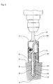
- numeral 1 denotes a body having a shank 2 which is to be connected to a drive spindle (not shown), provided at the center of the top face thereof and a drill bit 3 fixed at the center of the bottom face thereof.
- a drill edge 4 provided on the bottom of the drill bit 3 is the same as that of a known drilling tool for drilling an ordinary straight hole.
- Numeral 5 denotes a cylindrical sleeve arranged freely movably in the vertical direction relative to the body portion 1, with a contact portion 6 which makes contact with the surface of an object to be drilled being formed at the lower end thereof.
- Lower part of the body 1 is slidably fitted in an upper opening of the cylindrical sleeve 5, a lock pin 8 provided to project on the body portion 1 is engaged in an elongated hole 7 made in the cylindrical sleeve 5 to regulate the range of vertical movement of the body 1 and the cylindrical sleeve 5.
- the lock pin 8 is held in a holding hole 9 made in the body portion 1 and made to project into the elongated hole 7 under the pressure of a spring 10, thereby enabling it to separate the body 1 and the cylindrical sleeve 5 under such a condition that the lock pin 8 is pressed into the holding hole 9 side against the resistance of the spring 10.
- Numeral 11 denotes a guide groove made on the side face of the drill bit 3 by cutting therein in the axial direction, while the guide groove 11 has a sloped surface 12 formed at the bottom thereof to slope outwardly reaching the drill bit 3 surface.
- Numeral 13 denotes an undercut cutting member housed in the guide groove 11 to be freely movable within a predetermined range relative to the drill bit 3, with the lower half of the undercut cutting member 13 being constituted of a blade 14 which has an Appropriate degree of elasticity with an undercut cutting edge 15 being provided at the lower end thereof corresponding to the sloped surface 12 of the guide groove 11, and a support portion 16 being provided at the upper end of the undercut cutting member 13 projecting outward.
- Numeral 17 denotes a plate provided in the cylindrical sleeve 5 and engaged with the support portion 16 of the undercut cutting member 13, with a pull-up spring 18 being arranged between the plate 17 and the contact portion 6 of the cylindrical sleeve 5 so that, under the normal condition, the undercut cutting member 13 is pulled up together with the plate 17 relative to the drill bit 3 to retract the undercut cutting edge 15 into the guide groove 11 and the plate 17 is made contact with the bottom face of the body 1 under the pressure of the pull-up spring 18.
- Numeral 19 denotes an inverse U-shaped hole made in the body 1 with a plurality of balls being housed consecutively in the inverse U-shaped hole 19 to form a train of balls 20, while connecting rods 21, 22 are provided to project downwardly of the body 1 to make contact with both ends of the train of balls 20, with the lower end of one connecting rod 21 being brought into contact with the contact portion 6 of the cylindrical sleeve 5, and the lower end of the other connecting rod 22 being brought into contact with the plate 17, thereby forming the working force transmitting mechanism 23.
- Numeral 24 denotes an undercut marker provided on the.bottom face of the plate 17 near the periphery of the plate 17 to project downward, having a marking blade 24a at the lower end.
- a communicating hole 25 is provided in the contact portion 6 of the cylindrical sleeve 5 corresponding to the undercut marker 24 so that, when the plate 17 moves down in the cylindrical sleeve 5, the undercut marker 24 is passed through the communicating hole 25 thereby making the marking edge 24a projected below the contact portion 6.
- Numeral 26 denotes a cover attached on the outer circumference of the body 1, for stabilizing the lock pin 8 and the train of balls 20 in the body 1.
- the drill edge 4 of the drill bit 3 is pressed against the object A to be drilled to drill a drilled hole B.
- the drilled hole B reaches a predetermined depth and the contact portion 6 of the cylindrical sleeve 5 makes contact with the surface of the object to be drilled A.
- the body 1 is thrust into the cylindrical sleeve 5 and continues to move down so that drilling of the drilled hole B continues.
- the plate 17 is pressed down together with the undercut cutting member 13 over a greater distance than the downward movement of the body 1 against the resistance of the pull-up spring 18, and the undercut cutting edge 15 moves along the sloped surface 12 of the guide groove 11 to protrude outwardly of the drill bit 3 surface and starts cutting of the drilled hole wall.
- the undercut cutting edge 15 reaches the point of maximum protrusion on the drill bit 3 surface, to complete cutting of the undercut portion C where the wall of the hole is tapered to enlarge the diameter downward.
- the marking edge 24 of the undercut marker 23 protrudes from the communicating hole 25 downwardly of the contact portion 6 and is pressed against the surface of the object to be drilled A, thereby marking a circular line D on the surface of the object to be drilled A. Completion of the undercut portion C cutting process can be confirmed by observing the circular line D.
- the process proceeds in reversed order of the procedure described above; first the pull-up spring 18 pulls up the plate 17 and the undercut cutting member 13 and, at the same time, the cylindrical sleeve 5 returns to the initial position while the undercut cutting edge 15 retracts into the guide groove 11 and the drill edge 3 is pulled out of the drilled hole B to complete the drilling operation.
- the circular line D marked on the surface of the object to be drilled A provides various information even after the drilling operation has been completed.
- existence of the circular line D means that the hole is a drilled hole B with an undercut portion C being cut therein.
- radius of the circular line D is given a relationship with the depth of the drilled hole B or the position of the undercut portion C, it provides convenience in selecting the type of anchor bolt to be planted and other purposes.
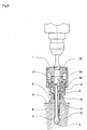
- movement of the working oil is used to operate the working force transmitting mechanism.
- an oil case 27 is attached to the body 1 with a cylinder 28 being installed suspended on the body 1 concentrically in the oil case 27, the upper end of the cylindrical sleeve 5 being fitted slidably between the oil case 27 and the cylinder 28 to form the first working oil chamber 29 and a working force transmitting sleeve 30 being fitted slidably between a cylindrical portion 28 and the drill bit 3 to form a second working oil chamber 31, while an oil passage hole 32 is provided to penetrate through the upper part of the cylinder 28 so that the first working oil chamber 29 and the second working oil chamber 31 communicate with each other, and the lower end of the working force transmitting sleeve 30 is engaged with the support portion 16 of the undercut cutting member 13 thereby constituting a working force transmitting mechanism 23.
- the drill edge 4 of the drill bit 3 is pressed against the object to be drilled A to drill the drilled hole B and, after the contact portion 6 of the cylindrical sleeve 5 makes contact with the surface of the object to be drilled A, the upper end of the cylindrical sleeve 5 is thrusted into the first working oil chamber 29 to move the working oil from the first working oil chamber 29 via the oil passage hole 32 into the second working oil chamber 31, thereby pressing down the working force transmitting sleeve 30.
Landscapes
- Engineering & Computer Science (AREA)
- Mechanical Engineering (AREA)
- Processing Of Stones Or Stones Resemblance Materials (AREA)
Claims (3)
- Outil de perçage pour percer un trou en contre-dépouille dans un objet plein, comprenant :caractérisé en ce que le mécanisme de transmission de force de travail comprend :un corps (1) comportant, au niveau de l'une de ses extrémités, une tige (2) et, au niveau de son autre extrémité, un foret (3) coaxial avec la tige ;un organe de transmission de poussée sous la forme d'un manchon cylindrique (5) disposé pour effectuer un mouvement axial coulissant autour d'une partie inférieure du corps et comportant, au niveau de l'une de ses extrémités, une partie de contact (6) qui vient en contact avec la surface de l'objet à percer ;une goupille de blocage (8) qui s'avance depuis le corps dans une fente longitudinale allongée (7) formée dans le manchon cylindrique ;une rainure de guidage longitudinale (11) formée dans la périphérie du trépan (3) et comportant une surface inclinée (12) au niveau de son extrémité inférieure ;un organe de coupe en contre-dépouille (13) logé dans la rainure de guidage pour pouvoir se déplacer librement longitudinalement et muni d'une arête de coupe en contre-dépouille (15) au niveau de son extrémité inférieure correspondant à la surface inclinée (12) ;un ressort de rappel (18) disposé entre la partie de contact (6) du manchon cylindrique et une plaque (17) en prise avec l'extrémité supérieure de l'organe de coupe en contre-dépouille (13) ; etun mécanisme de transmission de force de travail (23, 33) situé entre l'organe de transmission de poussée (5) et l'organe de coupe en contre-dépouille (13) et accouplé avec ceux-ci pour pousser l'organe de coupe en contre-dépouille à l'encontre de la sollicitation du ressort de rappel en réponse au déplacement du corps en direction de l'organe de transmission de poussée, afin d'amener ainsi l'arête de coupe en contre-dépouille à dépasser à l'extérieur de la surface du trépan,plusieurs billes logées les unes à la suite des autres dans une gorge en forme de U inversé (19) ménagée dans le corps, pour former un train de billes (20) ; etdeux tiges de liaison (21, 22) qui font saillie en bas du corps et sont en contact avec les deux extrémités du train de billes, l'extrémité inférieure de l'une (21) des tiges de liaison étant en contact avec la partie de contact du manchon cylindrique, tandis que l'extrémité inférieure de l'autre tige de liaison (22) est en contact avec la plaque en prise avec l'organe de coupe en contre-dépouille.
- Outil de perçage selon la revendication 1, comprenant égalementun marqueur de contre-dépouille (24) comportant une arête de marquage (24a) qui fait saillie depuis la face inférieure de la plaque (17) en prise avec l'organe de coupe en contre-dépouille (13) ; etun trou (25) formé dans la partie de contact (6) du manchon cylindrique en alignement avec le marqueur de contre-dépouille pour que l'arête de marquage (24a) puisse librement sortir du trou ou rentrer dans celui-ci.
- Outil de perçage pour percer un trou en contre-dépouille dans un objet plein, comprenant :caractérisé en ce que le mécanisme de transmission de force de travail comprend :un corps (1) comportant, au niveau de l'une de ses extrémités, une tige (2) et, au niveau de son autre extrémité, un foret (3) coaxial avec la tige ;un organe de transmission de poussée sous la forme d'un manchon cylindrique (5) disposé pour effectuer un mouvement axial coulissant autour d'une partie inférieure du corps et comportant, au niveau de l'une de ses extrémités, une partie de contact (6) qui vient en contact avec la surface de l'objet à percer ;une rainure de guidage longitudinale (11) formée dans la périphérie du trépan (3) et comportant une surface inclinée (12) au niveau de son extrémité inférieure ;un organe de coupe en contre-dépouille (13) logé dans la rainure de guidage pour pouvoir se déplacer librement longitudinalement et muni d'une arête de coupe en contre-dépouille (15) au niveau de son extrémité inférieure correspondant à la surface inclinée (12) ;un ressort de rappel (18) disposé entre la partie de contact (6) du manchon cylindrique et une plaque (17) en prise avec l'extrémité supérieure de l'organe de coupe en contre-dépouille (13) ; etun mécanisme de transmission de force de travail (23, 33) situé entre l'organe de transmission de poussée (5) et l'organe de coupe en contre-dépouille (13) et accouplé avec ceux-ci pour pousser l'organe de coupe en contre-dépouille à l'encontre de la sollicitation du ressort de rappel en réponse au déplacement du corps en direction de l'organe de transmission de poussée, afin d'amener ainsi l'arête de coupe en contre-dépouille à dépasser à l'extérieur de la surface du trépan,une première chambre à huile de travail (29) formée par un carter à huile (27) disposé sur le corps, un cylindre (28) disposé sur le corps de manière concentrique à l'intérieur du carter à huile et l'extrémité supérieure du manchon cylindrique (5) insérée de manière coulissante entre le carter à huile et le corps ;une seconde chambre à huile de travail (31) formée par le cylindre (28) et le corps du foret (3) et un manchon (30) en prise avec l'organe de coupe en contre-dépouille (13) et inséré de manière coulissante entre le cylindre et le corps du foret ; etun passage d'huile (32) ménagé à travers le cylindre (28) entre la seconde chambre à huile de travail (31) et la première chambre à huile de travail (29).
Applications Claiming Priority (3)
| Application Number | Priority Date | Filing Date | Title |
|---|---|---|---|
| JP40131/95 | 1995-02-28 | ||
| JP4013195 | 1995-02-28 | ||
| JP7040131A JP2862807B2 (ja) | 1995-02-28 | 1995-02-28 | アンダーカット部付き孔の穿孔装置 |
Publications (2)
| Publication Number | Publication Date |
|---|---|
| EP0729802A1 EP0729802A1 (fr) | 1996-09-04 |
| EP0729802B1 true EP0729802B1 (fr) | 2000-04-19 |
Family
ID=12572260
Family Applications (1)
| Application Number | Title | Priority Date | Filing Date |
|---|---|---|---|
| EP96301327A Expired - Lifetime EP0729802B1 (fr) | 1995-02-28 | 1996-02-27 | Foret pour le perçage de trous chambrés |
Country Status (5)
| Country | Link |
|---|---|
| US (1) | US5735650A (fr) |
| EP (1) | EP0729802B1 (fr) |
| JP (1) | JP2862807B2 (fr) |
| AU (1) | AU698900B2 (fr) |
| DE (1) | DE69607776T2 (fr) |
Families Citing this family (12)
| Publication number | Priority date | Publication date | Assignee | Title |
|---|---|---|---|---|
| JP2862830B2 (ja) * | 1996-03-13 | 1999-03-03 | 株式会社ミヤナガ | アンダーカット部付き孔の穿孔装置 |
| US5810523A (en) * | 1995-02-28 | 1998-09-22 | Kabushiki Kaisha Miyanaga | Apparatus for drilling a hole having an undercut space |
| AUPN674795A0 (en) * | 1995-11-23 | 1995-12-14 | Ramset Fasteners (Aust.) Pty. Limited | Undercutting drills |
| US5885294A (en) * | 1997-09-22 | 1999-03-23 | Ethicon, Inc. | Apparatus and method for anchoring a cord-like element to a workpiece |
| US6761516B2 (en) * | 2002-10-11 | 2004-07-13 | The Boeing Company | Method for generating holes in laminate materials |
| US20040149093A1 (en) * | 2003-01-30 | 2004-08-05 | Gordon Tang | Tool for forming an undercut hole and method for its use |
| CN1931550B (zh) * | 2006-10-11 | 2010-12-22 | 赖其淡 | 具有钻扩孔功能的钻头 |
| US8211182B2 (en) * | 2007-09-17 | 2012-07-03 | Linares Medical Devices, Llc | Hip socket with assembleable male ball shape having integrally formed ligament and female receiver and installation kit |
| JP5806782B2 (ja) | 2013-08-23 | 2015-11-10 | 株式会社ミヤナガ | 拡径孔部付き孔の穿孔装置 |
| DE102014003721A1 (de) * | 2014-03-18 | 2015-09-24 | Karl Storz Gmbh & Co. Kg | Werkzeug und Verfahren zum Erzeugen eines Hinterschnitts in einem Knochen |
| CN109570578B (zh) * | 2019-01-03 | 2020-12-04 | 上海友升铝业有限公司 | 一种可缩进式cnc加工用沉头刀具 |
| CN118977981B (zh) * | 2024-09-25 | 2025-12-16 | 湖北中烟工业有限责任公司 | 一种皮带输送机防积垢托辊 |
Family Cites Families (20)
| Publication number | Priority date | Publication date | Assignee | Title |
|---|---|---|---|---|
| US1536208A (en) * | 1925-01-14 | 1925-05-05 | George Hugh Foster | Expansible boring tool |
| GB518688A (en) * | 1938-09-02 | 1940-03-05 | Shawlock Inc | Improvements in or relating to a boring tool, particularly for boring taper holes |
| GB1184106A (en) * | 1967-04-18 | 1970-03-11 | John Darbyshire & Company Ltd | Improvements in or relating to Reamers |
| US3696454A (en) * | 1970-09-10 | 1972-10-10 | Teledyne Inc | Thread cutting die head |
| US3731942A (en) * | 1970-09-30 | 1973-05-08 | Buck Tool Co | Hydraulically actuated tool collet |
| JPS5850855B2 (ja) * | 1978-06-07 | 1983-11-12 | ヒルティ・アクチエンゲゼルシャフト | 穿孔機 |
| US4354559A (en) * | 1980-07-30 | 1982-10-19 | Tri-State Oil Tool Industries, Inc. | Enlarged borehole drilling method and apparatus |
| US4402642A (en) * | 1981-01-12 | 1983-09-06 | Universal Automatic Corporation | Machine tool bar feed |
| US4462726A (en) * | 1981-06-08 | 1984-07-31 | Irontite Products Co., Inc. | Apparatus for forming a groove |
| JPS60172408A (ja) * | 1984-02-17 | 1985-09-05 | Miyanaga:Kk | アンダ−カツト穿孔用打撃穿孔装置 |
| JPS60145005U (ja) * | 1984-03-08 | 1985-09-26 | 株式会社ミヤナガ | 拡径孔部削成装置 |
| JPH0110173Y2 (fr) * | 1984-09-07 | 1989-03-23 | ||
| US4635737A (en) * | 1984-03-08 | 1987-01-13 | Kabushiki Kaishi Miyanaga | Undercutting drill |
| JPH0239688Y2 (fr) * | 1986-06-10 | 1990-10-24 | ||
| JPH0829445B2 (ja) * | 1986-12-16 | 1996-03-27 | 株式会社ミヤナガ | 上向き拡径孔部削成装置 |
| DE3839617A1 (de) * | 1988-11-24 | 1990-05-31 | Fischer Artur Werke Gmbh | Vorrichtung zur herstellung einer hinterschneidung in einem bohrloch |
| JPH0411766Y2 (fr) * | 1989-03-08 | 1992-03-24 | ||
| JP2598515B2 (ja) * | 1989-04-24 | 1997-04-09 | 株式会社ミヤナガ | 拡径部付孔穿孔装置 |
| DE4014224A1 (de) * | 1990-05-04 | 1991-11-07 | Fischer Artur Werke Gmbh | Vorrichtung zur herstellung von bohrloechern mit hinterschneidung |
| FR2679293B1 (fr) * | 1991-07-16 | 1999-01-22 | Inst Francais Du Petrole | Dispositif d'actionnement associe a une garniture de forage et comportant un circuit hydrostatique en fluide de forage, methode d'actionnement et leur application. |
-
1995
- 1995-02-28 JP JP7040131A patent/JP2862807B2/ja not_active Expired - Fee Related
-
1996
- 1996-01-17 US US08/587,395 patent/US5735650A/en not_active Expired - Lifetime
- 1996-02-12 AU AU44460/96A patent/AU698900B2/en not_active Ceased
- 1996-02-27 DE DE69607776T patent/DE69607776T2/de not_active Expired - Fee Related
- 1996-02-27 EP EP96301327A patent/EP0729802B1/fr not_active Expired - Lifetime
Also Published As
| Publication number | Publication date |
|---|---|
| EP0729802A1 (fr) | 1996-09-04 |
| US5735650A (en) | 1998-04-07 |
| AU4446096A (en) | 1996-09-05 |
| JPH08229931A (ja) | 1996-09-10 |
| DE69607776T2 (de) | 2000-11-23 |
| DE69607776D1 (de) | 2000-05-25 |
| JP2862807B2 (ja) | 1999-03-03 |
| AU698900B2 (en) | 1998-11-12 |
Similar Documents
| Publication | Publication Date | Title |
|---|---|---|
| EP0729802B1 (fr) | Foret pour le perçage de trous chambrés | |
| CA1157464A (fr) | Outil de chambrage dans un alesage | |
| AU619106B2 (en) | Bit for drilling an undercut hole | |
| US6276247B1 (en) | Adjustable punch assembly with releasable locking | |
| HK1006291B (en) | Bit for drilling an undercut hole | |
| EP0395620A3 (fr) | Outil de carottage | |
| US4202557A (en) | Drilling device | |
| US4444279A (en) | Drilling tool | |
| ATE68735T1 (de) | Spannfutter fuer werkzeuge. | |
| JPH02162005A (ja) | アンダカツト部を有する穿孔を製作するための穿孔装置 | |
| US5664900A (en) | Dowel joint system for connecting elements of a solid material | |
| EP0387228A2 (fr) | Accouplement d'outil entre un porte-outil et une broche de machine | |
| US2192528A (en) | Depth stop for a countersinking or boring tool | |
| US5810523A (en) | Apparatus for drilling a hole having an undercut space | |
| US4775160A (en) | Clamping chuck for drill bits and chisel bits | |
| US1805515A (en) | Inside pipe cutter | |
| US4843929A (en) | Method and device for connecting a holder body with a tool head | |
| JPH03107607A (ja) | 拡開アンカーの下穴アンダーカット装置 | |
| AU693051B2 (en) | Apparatus for drilling a hole having an undercut space | |
| US4755088A (en) | Hole saw unjamming tool | |
| GB2053042A (en) | Drilling tool | |
| JP2677948B2 (ja) | コアドリル | |
| US3341213A (en) | Tool holder | |
| JPH0110174Y2 (fr) | ||
| US4676701A (en) | Slug retainer |
Legal Events
| Date | Code | Title | Description |
|---|---|---|---|
| PUAI | Public reference made under article 153(3) epc to a published international application that has entered the european phase |
Free format text: ORIGINAL CODE: 0009012 |
|
| AK | Designated contracting states |
Kind code of ref document: A1 Designated state(s): DE FR GB |
|
| 17P | Request for examination filed |
Effective date: 19960930 |
|
| 17Q | First examination report despatched |
Effective date: 19971006 |
|
| GRAG | Despatch of communication of intention to grant |
Free format text: ORIGINAL CODE: EPIDOS AGRA |
|
| GRAG | Despatch of communication of intention to grant |
Free format text: ORIGINAL CODE: EPIDOS AGRA |
|
| GRAH | Despatch of communication of intention to grant a patent |
Free format text: ORIGINAL CODE: EPIDOS IGRA |
|
| GRAH | Despatch of communication of intention to grant a patent |
Free format text: ORIGINAL CODE: EPIDOS IGRA |
|
| GRAA | (expected) grant |
Free format text: ORIGINAL CODE: 0009210 |
|
| AK | Designated contracting states |
Kind code of ref document: B1 Designated state(s): DE FR GB |
|
| REF | Corresponds to: |
Ref document number: 69607776 Country of ref document: DE Date of ref document: 20000525 |
|
| ET | Fr: translation filed | ||
| PLBE | No opposition filed within time limit |
Free format text: ORIGINAL CODE: 0009261 |
|
| STAA | Information on the status of an ep patent application or granted ep patent |
Free format text: STATUS: NO OPPOSITION FILED WITHIN TIME LIMIT |
|
| 26N | No opposition filed | ||
| REG | Reference to a national code |
Ref country code: GB Ref legal event code: IF02 |
|
| PGFP | Annual fee paid to national office [announced via postgrant information from national office to epo] |
Ref country code: DE Payment date: 20090219 Year of fee payment: 14 |
|
| PGFP | Annual fee paid to national office [announced via postgrant information from national office to epo] |
Ref country code: GB Payment date: 20090225 Year of fee payment: 14 |
|
| PGFP | Annual fee paid to national office [announced via postgrant information from national office to epo] |
Ref country code: FR Payment date: 20090213 Year of fee payment: 14 |
|
| GBPC | Gb: european patent ceased through non-payment of renewal fee |
Effective date: 20100227 |
|
| REG | Reference to a national code |
Ref country code: FR Ref legal event code: ST Effective date: 20101029 |
|
| PG25 | Lapsed in a contracting state [announced via postgrant information from national office to epo] |
Ref country code: FR Free format text: LAPSE BECAUSE OF NON-PAYMENT OF DUE FEES Effective date: 20100301 |
|
| PG25 | Lapsed in a contracting state [announced via postgrant information from national office to epo] |
Ref country code: DE Free format text: LAPSE BECAUSE OF NON-PAYMENT OF DUE FEES Effective date: 20100901 |
|
| PG25 | Lapsed in a contracting state [announced via postgrant information from national office to epo] |
Ref country code: GB Free format text: LAPSE BECAUSE OF NON-PAYMENT OF DUE FEES Effective date: 20100227 |