EP0729880A2 - Elektrisch unterstütztes pedalbetriebenes Fahrzeug - Google Patents
Elektrisch unterstütztes pedalbetriebenes Fahrzeug Download PDFInfo
- Publication number
- EP0729880A2 EP0729880A2 EP96103306A EP96103306A EP0729880A2 EP 0729880 A2 EP0729880 A2 EP 0729880A2 EP 96103306 A EP96103306 A EP 96103306A EP 96103306 A EP96103306 A EP 96103306A EP 0729880 A2 EP0729880 A2 EP 0729880A2
- Authority
- EP
- European Patent Office
- Prior art keywords
- battery voltage
- threshold value
- battery
- drive system
- current
- Prior art date
- Legal status (The legal status is an assumption and is not a legal conclusion. Google has not performed a legal analysis and makes no representation as to the accuracy of the status listed.)
- Granted
Links
- 230000007423 decrease Effects 0.000 claims description 70
- 238000000034 method Methods 0.000 claims description 52
- 230000003247 decreasing effect Effects 0.000 claims description 28
- 238000001514 detection method Methods 0.000 claims description 12
- 230000001419 dependent effect Effects 0.000 claims description 2
- 230000008569 process Effects 0.000 description 38
- 238000011946 reduction process Methods 0.000 description 9
- 230000009467 reduction Effects 0.000 description 7
- 230000003446 memory effect Effects 0.000 description 6
- 230000000007 visual effect Effects 0.000 description 6
- 230000006870 function Effects 0.000 description 5
- 230000004397 blinking Effects 0.000 description 4
- 230000008859 change Effects 0.000 description 4
- 238000010586 diagram Methods 0.000 description 4
- 230000007246 mechanism Effects 0.000 description 3
- 238000012544 monitoring process Methods 0.000 description 3
- 230000035939 shock Effects 0.000 description 3
- 230000003466 anti-cipated effect Effects 0.000 description 1
- 230000008901 benefit Effects 0.000 description 1
- 238000007599 discharging Methods 0.000 description 1
- 230000000694 effects Effects 0.000 description 1
- 230000004048 modification Effects 0.000 description 1
- 238000012986 modification Methods 0.000 description 1
- 238000012360 testing method Methods 0.000 description 1
Images



Classifications
-
- B—PERFORMING OPERATIONS; TRANSPORTING
- B62—LAND VEHICLES FOR TRAVELLING OTHERWISE THAN ON RAILS
- B62M—RIDER PROPULSION OF WHEELED VEHICLES OR SLEDGES; POWERED PROPULSION OF SLEDGES OR SINGLE-TRACK CYCLES; TRANSMISSIONS SPECIALLY ADAPTED FOR SUCH VEHICLES
- B62M6/00—Rider propulsion of wheeled vehicles with additional source of power, e.g. combustion engine or electric motor
- B62M6/40—Rider propelled cycles with auxiliary electric motor
- B62M6/45—Control or actuating devices therefor
-
- B—PERFORMING OPERATIONS; TRANSPORTING
- B60—VEHICLES IN GENERAL
- B60L—PROPULSION OF ELECTRICALLY-PROPELLED VEHICLES; SUPPLYING ELECTRIC POWER FOR AUXILIARY EQUIPMENT OF ELECTRICALLY-PROPELLED VEHICLES; ELECTRODYNAMIC BRAKE SYSTEMS FOR VEHICLES IN GENERAL; MAGNETIC SUSPENSION OR LEVITATION FOR VEHICLES; MONITORING OPERATING VARIABLES OF ELECTRICALLY-PROPELLED VEHICLES; ELECTRIC SAFETY DEVICES FOR ELECTRICALLY-PROPELLED VEHICLES
- B60L15/00—Methods, circuits, or devices for controlling the traction-motor speed of electrically-propelled vehicles
- B60L15/20—Methods, circuits, or devices for controlling the traction-motor speed of electrically-propelled vehicles for control of the vehicle or its driving motor to achieve a desired performance, e.g. speed, torque, programmed variation of speed
-
- B—PERFORMING OPERATIONS; TRANSPORTING
- B60—VEHICLES IN GENERAL
- B60L—PROPULSION OF ELECTRICALLY-PROPELLED VEHICLES; SUPPLYING ELECTRIC POWER FOR AUXILIARY EQUIPMENT OF ELECTRICALLY-PROPELLED VEHICLES; ELECTRODYNAMIC BRAKE SYSTEMS FOR VEHICLES IN GENERAL; MAGNETIC SUSPENSION OR LEVITATION FOR VEHICLES; MONITORING OPERATING VARIABLES OF ELECTRICALLY-PROPELLED VEHICLES; ELECTRIC SAFETY DEVICES FOR ELECTRICALLY-PROPELLED VEHICLES
- B60L50/00—Electric propulsion with power supplied within the vehicle
- B60L50/50—Electric propulsion with power supplied within the vehicle using propulsion power supplied by batteries or fuel cells
- B60L50/53—Electric propulsion with power supplied within the vehicle using propulsion power supplied by batteries or fuel cells in combination with an external power supply, e.g. from overhead contact lines
-
- B—PERFORMING OPERATIONS; TRANSPORTING
- B60—VEHICLES IN GENERAL
- B60L—PROPULSION OF ELECTRICALLY-PROPELLED VEHICLES; SUPPLYING ELECTRIC POWER FOR AUXILIARY EQUIPMENT OF ELECTRICALLY-PROPELLED VEHICLES; ELECTRODYNAMIC BRAKE SYSTEMS FOR VEHICLES IN GENERAL; MAGNETIC SUSPENSION OR LEVITATION FOR VEHICLES; MONITORING OPERATING VARIABLES OF ELECTRICALLY-PROPELLED VEHICLES; ELECTRIC SAFETY DEVICES FOR ELECTRICALLY-PROPELLED VEHICLES
- B60L58/00—Methods or circuit arrangements for monitoring or controlling batteries or fuel cells, specially adapted for electric vehicles
- B60L58/10—Methods or circuit arrangements for monitoring or controlling batteries or fuel cells, specially adapted for electric vehicles for monitoring or controlling batteries
- B60L58/12—Methods or circuit arrangements for monitoring or controlling batteries or fuel cells, specially adapted for electric vehicles for monitoring or controlling batteries responding to state of charge [SoC]
- B60L58/14—Preventing excessive discharging
-
- B—PERFORMING OPERATIONS; TRANSPORTING
- B60—VEHICLES IN GENERAL
- B60L—PROPULSION OF ELECTRICALLY-PROPELLED VEHICLES; SUPPLYING ELECTRIC POWER FOR AUXILIARY EQUIPMENT OF ELECTRICALLY-PROPELLED VEHICLES; ELECTRODYNAMIC BRAKE SYSTEMS FOR VEHICLES IN GENERAL; MAGNETIC SUSPENSION OR LEVITATION FOR VEHICLES; MONITORING OPERATING VARIABLES OF ELECTRICALLY-PROPELLED VEHICLES; ELECTRIC SAFETY DEVICES FOR ELECTRICALLY-PROPELLED VEHICLES
- B60L58/00—Methods or circuit arrangements for monitoring or controlling batteries or fuel cells, specially adapted for electric vehicles
- B60L58/10—Methods or circuit arrangements for monitoring or controlling batteries or fuel cells, specially adapted for electric vehicles for monitoring or controlling batteries
- B60L58/18—Methods or circuit arrangements for monitoring or controlling batteries or fuel cells, specially adapted for electric vehicles for monitoring or controlling batteries of two or more battery modules
- B60L58/21—Methods or circuit arrangements for monitoring or controlling batteries or fuel cells, specially adapted for electric vehicles for monitoring or controlling batteries of two or more battery modules having the same nominal voltage
-
- B—PERFORMING OPERATIONS; TRANSPORTING
- B62—LAND VEHICLES FOR TRAVELLING OTHERWISE THAN ON RAILS
- B62M—RIDER PROPULSION OF WHEELED VEHICLES OR SLEDGES; POWERED PROPULSION OF SLEDGES OR SINGLE-TRACK CYCLES; TRANSMISSIONS SPECIALLY ADAPTED FOR SUCH VEHICLES
- B62M6/00—Rider propulsion of wheeled vehicles with additional source of power, e.g. combustion engine or electric motor
- B62M6/40—Rider propelled cycles with auxiliary electric motor
- B62M6/55—Rider propelled cycles with auxiliary electric motor power-driven at crank shafts parts
-
- B—PERFORMING OPERATIONS; TRANSPORTING
- B62—LAND VEHICLES FOR TRAVELLING OTHERWISE THAN ON RAILS
- B62M—RIDER PROPULSION OF WHEELED VEHICLES OR SLEDGES; POWERED PROPULSION OF SLEDGES OR SINGLE-TRACK CYCLES; TRANSMISSIONS SPECIALLY ADAPTED FOR SUCH VEHICLES
- B62M6/00—Rider propulsion of wheeled vehicles with additional source of power, e.g. combustion engine or electric motor
- B62M6/80—Accessories, e.g. power sources; Arrangements thereof
- B62M6/90—Batteries
-
- B—PERFORMING OPERATIONS; TRANSPORTING
- B60—VEHICLES IN GENERAL
- B60L—PROPULSION OF ELECTRICALLY-PROPELLED VEHICLES; SUPPLYING ELECTRIC POWER FOR AUXILIARY EQUIPMENT OF ELECTRICALLY-PROPELLED VEHICLES; ELECTRODYNAMIC BRAKE SYSTEMS FOR VEHICLES IN GENERAL; MAGNETIC SUSPENSION OR LEVITATION FOR VEHICLES; MONITORING OPERATING VARIABLES OF ELECTRICALLY-PROPELLED VEHICLES; ELECTRIC SAFETY DEVICES FOR ELECTRICALLY-PROPELLED VEHICLES
- B60L2200/00—Type of vehicles
- B60L2200/12—Bikes
-
- B—PERFORMING OPERATIONS; TRANSPORTING
- B60—VEHICLES IN GENERAL
- B60L—PROPULSION OF ELECTRICALLY-PROPELLED VEHICLES; SUPPLYING ELECTRIC POWER FOR AUXILIARY EQUIPMENT OF ELECTRICALLY-PROPELLED VEHICLES; ELECTRODYNAMIC BRAKE SYSTEMS FOR VEHICLES IN GENERAL; MAGNETIC SUSPENSION OR LEVITATION FOR VEHICLES; MONITORING OPERATING VARIABLES OF ELECTRICALLY-PROPELLED VEHICLES; ELECTRIC SAFETY DEVICES FOR ELECTRICALLY-PROPELLED VEHICLES
- B60L2200/00—Type of vehicles
- B60L2200/26—Rail vehicles
-
- B—PERFORMING OPERATIONS; TRANSPORTING
- B60—VEHICLES IN GENERAL
- B60L—PROPULSION OF ELECTRICALLY-PROPELLED VEHICLES; SUPPLYING ELECTRIC POWER FOR AUXILIARY EQUIPMENT OF ELECTRICALLY-PROPELLED VEHICLES; ELECTRODYNAMIC BRAKE SYSTEMS FOR VEHICLES IN GENERAL; MAGNETIC SUSPENSION OR LEVITATION FOR VEHICLES; MONITORING OPERATING VARIABLES OF ELECTRICALLY-PROPELLED VEHICLES; ELECTRIC SAFETY DEVICES FOR ELECTRICALLY-PROPELLED VEHICLES
- B60L2250/00—Driver interactions
- B60L2250/10—Driver interactions by alarm
-
- Y—GENERAL TAGGING OF NEW TECHNOLOGICAL DEVELOPMENTS; GENERAL TAGGING OF CROSS-SECTIONAL TECHNOLOGIES SPANNING OVER SEVERAL SECTIONS OF THE IPC; TECHNICAL SUBJECTS COVERED BY FORMER USPC CROSS-REFERENCE ART COLLECTIONS [XRACs] AND DIGESTS
- Y02—TECHNOLOGIES OR APPLICATIONS FOR MITIGATION OR ADAPTATION AGAINST CLIMATE CHANGE
- Y02T—CLIMATE CHANGE MITIGATION TECHNOLOGIES RELATED TO TRANSPORTATION
- Y02T10/00—Road transport of goods or passengers
- Y02T10/60—Other road transportation technologies with climate change mitigation effect
- Y02T10/64—Electric machine technologies in electromobility
-
- Y—GENERAL TAGGING OF NEW TECHNOLOGICAL DEVELOPMENTS; GENERAL TAGGING OF CROSS-SECTIONAL TECHNOLOGIES SPANNING OVER SEVERAL SECTIONS OF THE IPC; TECHNICAL SUBJECTS COVERED BY FORMER USPC CROSS-REFERENCE ART COLLECTIONS [XRACs] AND DIGESTS
- Y02—TECHNOLOGIES OR APPLICATIONS FOR MITIGATION OR ADAPTATION AGAINST CLIMATE CHANGE
- Y02T—CLIMATE CHANGE MITIGATION TECHNOLOGIES RELATED TO TRANSPORTATION
- Y02T10/00—Road transport of goods or passengers
- Y02T10/60—Other road transportation technologies with climate change mitigation effect
- Y02T10/70—Energy storage systems for electromobility, e.g. batteries
-
- Y—GENERAL TAGGING OF NEW TECHNOLOGICAL DEVELOPMENTS; GENERAL TAGGING OF CROSS-SECTIONAL TECHNOLOGIES SPANNING OVER SEVERAL SECTIONS OF THE IPC; TECHNICAL SUBJECTS COVERED BY FORMER USPC CROSS-REFERENCE ART COLLECTIONS [XRACs] AND DIGESTS
- Y02—TECHNOLOGIES OR APPLICATIONS FOR MITIGATION OR ADAPTATION AGAINST CLIMATE CHANGE
- Y02T—CLIMATE CHANGE MITIGATION TECHNOLOGIES RELATED TO TRANSPORTATION
- Y02T10/00—Road transport of goods or passengers
- Y02T10/60—Other road transportation technologies with climate change mitigation effect
- Y02T10/72—Electric energy management in electromobility
Definitions
- This invention relates to an electrically assisted pedal operated vehicle, in particular bicycle, comprising a human power drive system and an electrical drive system provided in parallel to each other, whereby said electrical drive system further comprises an electric motor and at least one battery as a power source for said electric motor, and a control system for controlling an assist torque of said electrical drive system in accordance with a torque applied to said human power drive system by a user of said vehicle and a method of controlling the discharge of at least one battery for an electric motor of an electrically assisted pedal operated vehicle, in particular bicycle, comprising a human power drive system and an electrical drive system provided in parallel to each other, whereby said electrical drive system further comprises an electric motor and at least one battery as a power source for said electric motor, and a control system for controlling an assist torque of said electrical drive system in accordance with a torque applied to said human power drive system by a user of said vehicle.
- Some motor-assisted bicycles are constituted to supply an assist torque from a motor in proportion to the pedal force applied to the pedals by the rider.
- the battery voltage since the discharge current of the secondary battery changes from moment to moment, the battery voltage also changes according to decrease in the voltage due to internal resistance. Therefore, if the threshold value for stopping the power supply system is made constant and a large current flows out from the battery, the battery voltage decreases below the threshold value although the battery has still a remaining poker. As a result, the battery ends up in being charged while it is not discharged enough.
- the current value changes largely because the current value is changed according to the pedal force applied to the pedals.
- the above-mentioned technique has also a disadvantage that the software design becomes complicated because plural threshold values have to be set according to amounts of changes in the current values. Even if the plural threshold values are set, when the output current changes in between adjacent threshold values, the threshold value becomes constant. Therefore, it is likely that the control system for supplying power to the motor is stopped when the stop is not required, or the power remains to be supplied when the stop is required, and results in excessive discharge.
- an objective of the present invention to provide an improved electrically assisted pedal operated vehicle as indicated above which is capable of reliably controlling the battery voltage in order to prevent an excessive discharge and occurrence of the memory effect of said battery.
- this objective is solved for an electrically assisted pedal operated vehicle as indicated above by a means for determining at least one threshold value according to a current valve of said at least one battery for controlling the discharge of said at least one battery.
- this objective is solved for a method as indicated above in that at least one threshold value is determined according to a detected current value of said battery and that the discharge of said battery is controlled in dependence of the current values detected.
- said electrically assisted pedal operated vehicle comprises control means for controlling the current from said battery in accordance with said torque applied to said human power drive system, voltage detection means for detecting the voltage of said battery, and current detection means for detecting the value of said current.
- said means for determining said at least one threshold value is capable of continuously changing said threshold value to be generally constant when said current value is between zero and a first limit value.
- This effect may be further enhanced when said means for determining said at least one threshold value is capable of continuously changing said threshold value so that said threshold value decreases with the increase of said current value to be generally constant when said current value is equal to or larger than a second limit value being smaller than a possible maximum value of said current.
- said electrically assisted pedal operated vehicle further comprises a warning cutoff determination section for comparing said battery voltage with said at least one threshold value and for indicating and cutting off the current supply to said electric motor when the remaining battery voltage is small.
- the adaptability to different operational conditions is enhancable when said means for determining said at least one threshold value is capable of determining a plurality of threshold values of different levels.
- warning cutoff determination section is capable of gradually decreasing the ratio of said assist torque to said torque applied to said human power drive system as an indication of low remaining battery voltage.
- said means of determining said plurality of threshold valves is capable of determining said threshold values at three levels and said warring cutoff determination section is capable of indicating by means of light means and/or sound means that said battery voltage is passing the maximum level, by means of a force device for gradually decreasing the ratio of said assist torque to said torque applied to said human power drive system that said battery voltage is passing the medium level, and by means of a force device that said battery voltage is passing the minimum level.
- the threshold value changes according to the change in the current value of the secondary battery. Therefore, an optimum threshold value corresponding to the current value of the secondary battery is continuously set and the secondary battery voltage can be reliably monitored and controlled.
- the threshold value changes in inverse proportion to the secondary battery current
- the threshold value does not increase with the decrease in the current value but remains constant while the current value is equal to or smaller than the first boundary value.
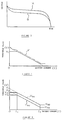
- the reason for setting the threshold value in this way is as follows. That is to say, as shown in FIG. 3, while the battery voltage decreases with the lapse of time of use, comparison between a new secondary battery (shown with A in the figure) and an old secondary battery or a secondary battery in which the memory effect has occurred (shown with B in the figure) shows that the old battery shows steeper decrease in the battery voltage after starting discharge. As a result, as shown with a phantom line in FIG. 4, the battery voltage decreases rapidly when only a small current is discharged.
- the threshold value is changed in inverse proportion over the entire range of the secondary battery current value as shown with the sloped line (including the broken line) in FIG 4, the battery voltage decreases below the threshold value immediately after starting discharge, and a process for stopping the discharge is carried out. Therefore, the secondary battery becomes practically useless when it is old to a certain extent.
- the upper limit of the threshold value is set within a low range of current value, the battery voltage does not decrease below the threshold value as a result of rapid decrease immediately after starting discharge. Therefore, the secondary battery is used effectively.
- the lower limit of the threshold value is set within a high range of current value, an appropriate process such as stopping the control system can be applied when the battery voltage becomes equal to or lower than the threshold value, preventing the secondary battery from being excessively discharged and prolonging the life of the secondary battery.
- the user may be appropriately informed in steps according to the extent of lowering in the battery voltage.
- a system can be constituted with high safety to provide information perceived by visual and hearing senses in the first step, information perceived by bodily feeling such as decrease in the ratio of assist torque in the second step, and information on stop of assist torque in the third step.
- the user can learn that the battery voltage has decreased to the first level. Furthermore, since the information perceived by the bodily feeling is given when the battery voltage decreases to or below the lower level of threshold value, the user can learn that the battery voltage has decreased to the second level. Even if the user overlooked the information that can be perceived by the visual and hearing senses, the user can reliably recognize the decrease in the battery voltage.
- the ratio of the assist torque to the human power is gradually decreased and the load on the user is gradually increased, the user can reliably learn that the battery voltage has decreased. Furthermore, since the load on the user does not increase suddenly, the user can ride safely.
- the user can reliably learn the decrease in the battery voltage from the increase in the load on the user so that the battery is prevented from being discharged excessively. Furthermore, since the decrease in the assist torque to zero can be anticipated from the information perceived by the visual and hearing senses, safety is secured even if the load on the user is increased suddenly.
- the user can learn that the battery voltage has decreased to the first level. Since the ratio of the assist torque to the human power is gradually decreased when the battery voltage decreases to the second level, the load on the user increases gradually so that the user can learn reliably the decrease in the battery voltage. Furthermore, since the load on the user does not increase suddenly, the rider can ride safely. The user can anticipate the decrease in the battery voltage to the third level and the decrease in the assist torque to zero, the load on the user increases gradually with less shock so that the user can ride more safely.
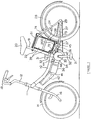
- FIG. 1 is a side view of a motor-assisted bicycle as an embodiment of this invention. Prior to the description of the embodiment, the constitution of the bicycle will be described.
- FIG. 1 shows the following components: A main tube 10 with its front end secured to a head tube 11 .
- a handlebar stem 12 is inserted in the head tube 11 so as to be rotatable about the axis of the head tube 11 .
- a right and left pair of forks 16 is secured to the lower portion of the handlebar stem 12 .
- a front wheel 14 is rotatably attached to the front forks 16 .
- Handlebars 18 extending in right and left directions are secured to the upper portion of the handlebar stem 12 .
- the main tube 10 extends from the front obliquely down backward and to its rear end is secured a middle lug 44 to which are secured a seat tube 22 and a rear tube 26 .
- the main tube 10 is curved so as to droop down so that even a female rider with a skirt can ride easily by stepping across the main tube 10 .
- the seat tube 22 supports a seat post 19 to which is secured a seat 20 .
- a pair of chain stays 27 To the rear tube 26 is secured a pair of chain stays 27 through a hanger lug 45 .
- the chain stays 27 and the seat tube 22 are connected to each other through a pair of seat stays 24 .
- the seat tube 26 , the seat stays 24 , the rear tube 26 and the chain stays 27 constitute a generally triangular shape in side view so as to support the weight of the rider when the rider rides the bicycle.
- To the connecting portions of the seat stays 24 and the chain stays 27 To the connecting portions of the seat stays 24 and the chain stays 27 is rotatably attached a rear wheel 28 .
- a power unit 34 is attached to a position below the middle lug (44) and the hanger lug 45 through brackets 46 and 47 .
- the power unit 34 is made up of a human power drive system, a motor drive system, and a resultant force mechanism for combining the power of both systems.
- a crankshaft 33 to which are attached cranks 32 to each of which is attached a pedal 31 .
- the symbol 36 denotes a motor.
- Rotation of the crankshaft 33 when the user depresses the pedals 31 is transmitted through one mechanism in the power unit 34 to the chain 37 and further to the rear wheel 28 through a freewheel 29 .
- the motor-assisted bicycle is propelled.
- the motor 36 is rotated on the other hand, the rotation of the rotor of the motor 36 is transmitted through the other mechanism in the power unit 34 to the chain 37 . This also rotates the rear wheel 28.
- the motor-assisted bicycle is provided with the human power drive system using the human power transmitted through the crankshaft 33 and with the motor drive system using power of the motor 36 .
- a casing 41 is attached under the main tube 10 .
- a controller 42 is disposed in the casing 41 .
- To the motor 36 is supplied drive current from chargeable (secondary) batteries 39 . It is arranged so that the batteries 39 supply current to the motor 36 and the controller 42 regulates the amount of the current. That is to say, when the human drive power or the pedal force applied through the pedals 31 , crank 32 , and crankshaft 33 is great, the controller 42 increases the current flowing to the motor 36 and when the pedal force is small, the controller 42 decreases the current flowing to the motor 36 . This makes it possible to increase the drive force of the motor 36 when the load on the rider is great so that the load on the rider is alleviated.
- the batteries 39 are stowed in two layers in am inner box 38 which in turn is stowed in an outer box 40 .
- the outer box 40 is disposed between the seat tube 22 and the rear wheel 28 , and secured to the seat tube 22 , seat stays 24 , and rear tubes 26 .
- a top lid 61 covers the outer box 40 . When the top lid 61 is open, the inner box 38 can be put into or taken out of the outer box 40 .
- FIG. 2 is a block diagram generally showing the control circuit.
- data representing the pedal force on the pedals 31 is inputted from a torque sensor 131 disposed in the power unit 34 through an interface 132 to a torque voltage detection section 130 of the controller 42 .
- the torque voltage detection section 130 converts the above-mentioned data to appropriate process signals arid outputs them to an indication current calculation section 101 .
- the indication current calculation section 101 calculates an indication current in proportion to the pedal force and outputs the data to a PWM calculation section 102 .
- the PWM calculation section 102 calculates a duty ratio of pulse current corresponding to the indication current, and outputs the calculated result through an interface 103 to a current control section (104).
- the current control section 104 controls so that the current pulse of the duty ratio calculated in the PWM calculation section 102 is supplied from the batteries 39 to the motor 36 .
- the current supplied to the motor 36 is detected with a current sensor (current detection means) 135 and the data representing the current is output through an interface 136 to a current detection section 137 .
- the current detection section 137 converts the data representing the current to an appropriate process signal and outputs it to a threshold value calculation section 108 .
- the threshold value calculation section 108 calculates two levels of threshold values V th1 and V th2 .
- the threshold value calculation section 108 reads an internal resistance value R , of the batteries 39 , stored in a memory 109 and calculates the values shown by the following equations, assuming I as the value of current. (1) V th1 - V 1 - IR (2) V th2 - V 2 - IR
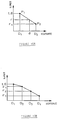
- FIG. 5 is a graph showing the first threshold value (sub-threshold value) V th1 and the second threshold value (sub-threshold value) V th2 calculated from the above-mentioned equations.
- the gradient of the oblique line shows the internal resistance R .
- the values V 1 and V 2 are determined by tests to obtain appropriate threshold values.
- the value V 1 is set so that the battery voltage V does not become lower than the first threshold value V th1 when remaining power of the batteries is sufficient.
- the value V 2 is set so that the battery voltage V becomes lower than the second threshold value V th2 when remaining power of the batteries is considerably small.
- the threshold value calculation section 108 When the current value I is equal to or smaller than the first boundary value I 1 , the threshold value calculation section 108 does not perform the above calculation but reads threshold values V f01 and V f11 stored in a memory 109 . When the current value I is equal to or greater than the second boundary value I 2 , the threshold value calculation section 108 does not perform the above calculation but reads threshold values V f02 and V f12 stored in the memory 109 .
- the first threshold value V th1 and the second threshold value V th2 obtained by calculation or reading are output to a warning-cutoff determination section (informing means) 110 .
- a voltage sensor (voltage detection means) 105 is connected to the batteries 39 .
- the data representing the voltage of the batteries 39 is output through an interface 106 to a voltage detection section 107 of the controller 42 .
- the voltage detection section 107 converts the above-mentioned data to an appropriate process signal and outputs it to the warning-cutoff determination section 110 .
- the warning-cutoff determination section 110 performs calculation with the following equation using the detected voltage v to determine a battery voltage V .
- the warning-cutoff determination section 110 compares the battery voltage V with the first and second threshold values V th1 and V th2 .
- an LED (not shown) provided on the handlebars 18 is made to blink. From the blinking of the LED, the rider learns that the remaining battery power has become small.
- the warning-cutoff determination section 110 supplies an exciting current to a coil (not shown) of a relay 111 interposed between the motor 36 and the current control section 104 when the battery voltage V is higher than the second threshold value V th2 ; otherwise the current supply is stopped.
- the relay 111 is of a normally open type so as to make connection, while the exciting current is being supplied through the interface 112 , between the motor 36 and the current control section 104 , and breaks that connection when the exciting current supply is stopped. With this constitution, current supply to the motor 36 is stopped when the voltage of the batteries 39 becomes equal to or lower than the second threshold value V th2 .
- the warning-cutoff determination section 110 when the voltage of the batteries 39 is equal to or lower than the second threshold value V th2 , gives a signal to the indication current calculation section 101 so as to make the indication current zero. This stops current supply to the motor 36 even if, for example, the contact points of the relay 111 are caused to remain in contact with each other as caused by sparking or the like.
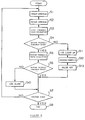
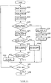
- step S1 When the bicycle is pedalled, an assist torque in proportion to the pedal force of the rider is output from the motor 36 to the power unit 34 .
- the current sensor 135 detects the current flowing to the motor 36 at that moment (step S1).
- the voltage sensor 105 detects the voltage v across the terminals of the batteries 39 (step S2).
- the voltage v includes a voltage drop portion IR caused by internal resistance of the batteries 39 .
- the second threshold value V th2 is calculated or read (step S3).
- the second threshold value V th2 is for discriminating whether or not to stop the current supply to the motor 36 and is compared with the voltage v - IR of the batteries 39 in the step S4.
- the result of the discrimination in the step S4 is YES and the process goes to the step S5 to calculate or read the first threshold value V th1 .
- the first threshold value V th1 is for discriminating whether or not a warning should be given to the rider when the battery voltage V decreases by a certain value.
- the first threshold value V th1 is compared with the battery voltage V .
- the discrimination result in the step S6 is YES, and the process goes to the step S7 to discriminate whether or not the control system for the assist torque should be ended.
- the process goes to Step S8 to end the control; otherwise the process returns to the step S1 and repeats the steps S1 - S7.
- the discrimination result in the step S4 is NO, and the process goes to the step S11 to light up the LED which has been blinking.
- the warning-cutoff discrimination section 110 outputs a signal for making the indication current value zero to the indication current calculation section 101 , and at the same time turns off the relay 111 (steps S12 and S13). This stops the current supply to the motor 36 and makes the assist torque zero. In this case the control system comes to an end (steps S7 and S8).
- the first and second threshold values V th1 and V th2 change in inverse proportion to the battery current value
- the first and second threshold values V th1 and V th2 are made constant when the current value I is not greater than the first boundary value I 1 or smaller than the second boundary value I 2 . Therefore, though the battery voltage V decreases rapidly immediately after starting discharge when the period of use is long or when the battery 39 voltage is low as a result of the memory effect, the battery voltage V does not decrease to or below the first threshold value V th1 or the second threshold value V th2 . Therefore, the process for warning or stopping discharge is not carried out, and the batteries 39 are used effectively. Furthermore, since the batteries 39 are prevented from being used at too low a voltage, the battery life is extended.
- the rider since the LED is made to blink when the battery voltage V decreases to or below the first threshold value V th1 , the rider may learn that the battery voltage V has decreased. At the same time, since the rider can anticipate the decrease in the assist ratio to zero, the rider can secure safety even if the load on the rider increases at that time. Furthermore, since the current supply to the motor 36 is stopped when the battery voltage V decreases to or below the second threshold value V th2 , the batteries are prevented from being excessively discharged and at the same time, the rider can reliably learn that there is no remaining power in the batteries.
- the arrangement may be such that a plural number of limit factors are stored in a memory 138 shown in FIG. 2, in advance in the order of addresses so as to decrease gradually, the limit factors are read in the order of addresses and multiplied by the indication current value, and the results are output to the PWM calculation section 102 .
- step S7 By controlling in this way, excessive discharge is prevented because the control system comes to an end (step S7) when the battery voltage V decreases below the second threshold value V th2 . Furthermore, the battery capacity can be fully utilized because the batteries 39 can be used up until the battery voltage V decreases below the second threshold value V th2 .
- the second embodiment is characterized in that the threshold values are set at three levels so that three types of control are carried out corresponding to the extent of decrease in the battery voltage V .
- a warning with the LED is issued when the battery voltage decreases to or below the first threshold value V th1
- the gradual decrease in the assist torque is started when the battery voltage decreases to or below the second threshold value V th2
- the control system is stopped when the battery voltage decreases to or below the third threshold value V th3 .
- the threshold values V th1 , V th2 , and V th3 are made constant.
- FIG. 8 is a block diagram of a control circuit of the embodiment.
- data representing elapsed time is issued from a timer 150 and output through an interface 156 to a clock section 152 .
- the clock section 152 converts the data representing the elapsed time into suitable process signal and outputs it to a traveled distance calculation section 153 and to a current limit factor calculation section 154 .
- Data representing the bicycle speed detected with a bicycle speed sensor 155 is output through an interface (156)to the traveled distance calculation section 153 .
- the traveled distance calculation section 153 calculates the traveled distance of the bicycle by integrating the bicycle speed with time, and outputs the data representing the traveled distance to the current limit factor calculation section 154 .
- the current limit factor calculation section 154 calculates the limit factor when the assist torque is to be gradually decreased, and outputs data representing the limit factor to the indication current calculation section 101 .
- the indication current calculation section 101 outputs result of multiplying together the indication current calculated to be in proportion to the pedal force and the limit factor to the PWM calculation section 102 . As a result, the ratio of the assist torque to the pedal force decreases.
- the calculation of the limit factor is started by a command signal from a section 160 for warning, current gradual decrease, and cutoff discrimination.
- the limit factor is linearly decreased with the increase in the distance traveled by the bicycle as shown in FIG. 10(A). This causes the ratio of the assist torque to the pedal force to decrease with the traveled distance.
- the limit factor may also be decreased with the traveled time. Calculation of the limit factor in this case may be done by replacing the distance parameters in the above equation with time parameters. Furthermore, a control is also possible to calculate limit factors for both traveled distance and traveled time and whichever greater limit factor is employed. By controlling in this way, more assist torque is given to the rider to make the riding safer.
- the limit factor changes linearly with a small reduction rate in the first zone D 1 - D 2 .
- the reduction rate of the limit factor is slightly increased in the next zone D 2 - D 3 and further increased in the next zone D 3 - D 4 .
- the control shown in FIG. 10(B) may also be made so that the limit factor is reduced with the traveled time, or the limit factors are calculated for the traveled distance and traveled time respectively and whichever greater limit factor is employed.
- the control shown in FIG. 10(B) may also be made so that the reduction rate of the limit factor is increased when the traveled distance and traveled time reaches a next step D 1 , D 2 , ... .
- the threshold value calculation section 108 does not perform the calculation described above when the current value I is not greater than the first boundary value I 1 but reads threshold values V f01 , V f11 , and V f21 (See FIG. 9) stored in the memory 109 , and does not perform the calculation described above when the current value is not smaller than the second boundary value I 2 but reads threshold values V f02 , V f12 , and V f22 stored in the memory 109 .
- the first and second threshold values V th1 and V th2 obtained by calculation or reading are output to the section 160 for warning, current gradual decrease, and cutoff discrimination.
- the section 160 for warning, current gradual decrease, and cutoff discrimination compares the battery voltage V with the first, second and third threshold values V th1 , V th2 , and V th3 .
- the LED is caused to blink.
- a signal for limiting the current supplied to the motor 36 is output to the indication current calculation section 101 and at the same time the LED is caused to light up.
- step S20, S21 value of the current flowing to the motor 36 and the voltage at that time are detected.
- step S22 the third threshold value V th3 is calculated or read (step S22).
- the third threshold value V th3 is for discriminating whether or not the current supply to the motor 36 should be stopped.
- the process goes to the step S23 to compare the third threshold value V th3 with the battery voltage V or v - IR, of the batteries 39 .
- discrimination result in the step S23 is YES and the process goes to the step S24 and the second threshold value V th2 is calculated or read.
- the second threshold value V th2 is for discriminating whether or not the assist torque should be gradually decreased when the battery voltage has considerably decreased.
- the process goes to the step S25 to compare the second threshold value V th2 with the battery voltage V .
- discrimination result in the step S25 is YES and the process goes to the step S26 and the first threshold value V th1 is calculated or read.
- the first threshold value V th1 is for discriminating whether or not the rider should be warned when the battery voltage has decreased to some extent.
- the process goes to the step S27 to compare the first threshold value V th1 with the battery voltage V .
- discrimination result in the step S27 is YES and the process goes to the step S28 and whether or not the assist torque control system should be ended is discriminated. There are two cases in ending the control system; one is turning off the main switch and the other is reducing the assist torque to zero. In either case, the process goes to the step S29 to end the control system; otherwise the process returns to the step S20 and repeats the steps S20 - S29.
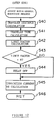
- FIG. 12 is a flow chart of the assist ratio gradual reduction process.
- First the traveled distance and the traveled time from the start of the assist ratio gradual reduction process are calculated steps S40 and S41 , and the limit factor is calculated S42 .
- the limit factor is calculated as described before from at least one of the traveled distance and the traveled time as shown in FIG. 10(A) or FIG. 10(B).
- the process goes from the step S43 to the step S45 and performs calculations of the indication current and multiplication of the indication current with the limit factor.
- the process returns to the step S28 in the main roatine and thereafter the process circulates through the steps S20 - S34, and S28.
- the discrimination result in the step S43 at that time is YES and the process goes to the step S44 to set a relay 111 to off.
- the calculation result of the indication current in the next step S45 becomes zero.
- current supply to the motor 36 is completely stopped.
- the discrimination result in the step S28 of the main routine becomes YES and the process goes to the step S29 to end the control system.
- the above is the process in which the battery 39 voltage V does not decrease below the third threshold value V th3 before the limit factor becomes zero.
- the main switch is turned on again after the limit value becomes zero and the control system is ended, the assist gradual reduction process is resumed from the beginning.
- the discrimination result in the step S23 is NO and the process goes to the step S31 to light up the LED which has been blinking.
- the section 160 for warning, current gradual decrease, and cutoff discrimination outputs a signal for making the indication current zero to the indication current calculation section 101 and turns off the relay 111 steps S32, and S33 .
- current supply to the motor 36 is completely stopped and the assist torque becomes zero.
- the discrimination result in the step S28 of the main routine becomes YES and the process goes to the step S29 to end the control system.
- the rider can learn the decrease in the battery voltage by the visual sense and the bodily feeling, and at the same time can anticipate the decrease in the assist ratio to zero. As a result, the rider can secure safety even when the load on the rider increases at that time. Since the load on the rider increases gradually, shocks are small and the rider can ride safely.
- optimum threshold values are continuously set according to the current value of the secondary battery to enable reliable control while monitoring the secondary battery voltage. Since the upper limit of the threshold value is set within a low current value range, the battery voltage does not decrease below the threshold value because of voltage drop immediately after starting discharge even with old batteries, the secondary batteries can be used effectively. Since the lower limit of the threshold value is set within a high current value range, the secondary batteries are prevented from being excessively discharged and the battery life is extended by carrying out appropriate process such as stopping the control system when the battery voltage decreases to or below the threshold value.
Landscapes
- Engineering & Computer Science (AREA)
- Transportation (AREA)
- Mechanical Engineering (AREA)
- Chemical & Material Sciences (AREA)
- Combustion & Propulsion (AREA)
- Power Engineering (AREA)
- Sustainable Development (AREA)
- Sustainable Energy (AREA)
- Life Sciences & Earth Sciences (AREA)
- Electric Propulsion And Braking For Vehicles (AREA)
- Charge And Discharge Circuits For Batteries Or The Like (AREA)
- Arrangement Or Mounting Of Propulsion Units For Vehicles (AREA)
- Secondary Cells (AREA)
Applications Claiming Priority (3)
| Application Number | Priority Date | Filing Date | Title |
|---|---|---|---|
| JP04415795A JP3688745B2 (ja) | 1995-03-03 | 1995-03-03 | 補助動力付き人力車両 |
| JP4415795 | 1995-03-03 | ||
| JP44157/95 | 1995-03-03 |
Publications (3)
| Publication Number | Publication Date |
|---|---|
| EP0729880A2 true EP0729880A2 (de) | 1996-09-04 |
| EP0729880A3 EP0729880A3 (de) | 1998-06-17 |
| EP0729880B1 EP0729880B1 (de) | 2002-08-28 |
Family
ID=12683787
Family Applications (1)
| Application Number | Title | Priority Date | Filing Date |
|---|---|---|---|
| EP96103306A Expired - Lifetime EP0729880B1 (de) | 1995-03-03 | 1996-03-04 | Elektrisch unterstütztes pedalbetriebenes Fahrzeug |
Country Status (6)
| Country | Link |
|---|---|
| US (1) | US5878831A (de) |
| EP (1) | EP0729880B1 (de) |
| JP (1) | JP3688745B2 (de) |
| CN (1) | CN1106315C (de) |
| DE (1) | DE69623149T2 (de) |
| TW (1) | TW429930U (de) |
Cited By (3)
| Publication number | Priority date | Publication date | Assignee | Title |
|---|---|---|---|---|
| EP0888960A3 (de) * | 1997-07-03 | 2000-07-05 | Honda Giken Kogyo Kabushiki Kaisha | Steuereinrichtung zur Regelung der Stromversorgung eines Fahrzeugs mit Hilfsmotor |
| EP2368745A1 (de) * | 2010-03-25 | 2011-09-28 | Sanyo Electric Co., Ltd. | Systemsteuervorrichtung für einen mobilen Fahrzeugaufbau und mobiler Fahrzeugaufbau |
| EP2436588A1 (de) * | 2010-09-30 | 2012-04-04 | Honda Motor Co., Ltd. | Steuerungsvorrichtung für ein Motorfahrrad |
Families Citing this family (28)
| Publication number | Priority date | Publication date | Assignee | Title |
|---|---|---|---|---|
| US6320339B1 (en) * | 2000-09-12 | 2001-11-20 | Universal Scientific Industrial Co., Ltd. | Control device for controlling current passing through a motor |
| US6765323B2 (en) * | 2001-09-28 | 2004-07-20 | Kabushiki Kaisha Moric | Method and device for detecting rotational drive force |
| JP3727315B2 (ja) * | 2003-04-01 | 2005-12-14 | 株式会社シマノ | 自転車用電源装置 |
| JP2006325372A (ja) * | 2005-05-20 | 2006-11-30 | Shimano Inc | 人力駆動車用直流電源装置 |
| JP4583490B1 (ja) * | 2009-06-19 | 2010-11-17 | パナソニック株式会社 | 電動補助自転車 |
| JP5564390B2 (ja) * | 2010-09-30 | 2014-07-30 | 本田技研工業株式会社 | 電動補助自転車の制御装置 |
| JP5564389B2 (ja) * | 2010-09-30 | 2014-07-30 | 本田技研工業株式会社 | 電動補助自転車の制御装置 |
| DE102011079094A1 (de) * | 2011-01-13 | 2012-07-19 | Johannes Biechele | Fahrradrahmen, Batteriepack und Fahrrad |
| US10086708B2 (en) * | 2011-03-31 | 2018-10-02 | Shimano Inc. | Bicycle component control apparatus |
| US9284016B2 (en) * | 2011-03-31 | 2016-03-15 | Shimano Inc. | Bicycle component control apparatus |
| TW201315650A (zh) * | 2011-10-11 | 2013-04-16 | 久鼎金屬實業股份有限公司 | 具有順暢變速功能之助力自行車 |
| US8751084B2 (en) | 2012-05-08 | 2014-06-10 | Curtis Instruments, Inc. | Vehicle component recognition and adjustment for energy efficiency |
| KR20140038050A (ko) * | 2012-09-19 | 2014-03-28 | 주식회사 만도 | 전기 자전거 및 그 제어방법 |
| US10170804B2 (en) * | 2015-06-15 | 2019-01-01 | Gs Yuasa International Ltd. | Monitoring device for secondary battery, battery pack, and vehicle |
| JP6534883B2 (ja) * | 2015-07-21 | 2019-06-26 | 株式会社シマノ | 自転車の制御装置およびこの制御装置を備える自転車のアシスト装置 |
| US9925999B2 (en) | 2015-09-29 | 2018-03-27 | Radio Flyer Inc. | Power assist wagon |
| US9857252B2 (en) * | 2015-11-24 | 2018-01-02 | GM Global Technology Operations LLC | Automated e-assist adjustment for an e-bike for elevation gains and loss |
| CN105957263B (zh) * | 2016-06-17 | 2019-01-25 | 浙江右边数字科技有限公司 | 车载终端、充电桩、电动自行车以及其租用系统及方法 |
| US10583852B2 (en) | 2016-11-02 | 2020-03-10 | Radio Flyer Inc. | Foldable wagon |
| FR3066981B1 (fr) * | 2017-05-31 | 2019-06-14 | Electricite De France | Dispositif de gestion d'un ensemble de propulsion electrique d'un vehicule |
| JP7343266B2 (ja) * | 2017-10-27 | 2023-09-12 | 株式会社シマノ | 人力駆動車両用制御装置 |
| USD866676S1 (en) | 2017-11-02 | 2019-11-12 | Radio Flyer Inc. | Foldable wagon |
| US10501146B2 (en) | 2018-04-17 | 2019-12-10 | GM Global Technology Operations LLC | Adaptive pedal assist systems and control logic for intelligent e-bikes |
| US11008063B2 (en) | 2018-06-25 | 2021-05-18 | GM Global Technology Operations LLC | Adaptive pedal assist systems and control logic with input torque filters for intelligent e-bikes |
| US11383787B2 (en) | 2018-09-26 | 2022-07-12 | GM Global Technology Operations LLC | Multi-axis pivoting coupler joints and drivetrain architectures for intelligent electric scooters |
| US11001152B2 (en) | 2018-09-26 | 2021-05-11 | GM Global Technology Operations LLC | Powertrain architectures and control algorithms for intelligent electric scooters |
| JP7147058B2 (ja) | 2019-04-25 | 2022-10-04 | 本田技研工業株式会社 | 自転車の電動アシスト装置及び自転車 |
| JP7514605B2 (ja) * | 2019-05-17 | 2024-07-11 | 株式会社シマノ | 人力駆動車用の制御装置 |
Family Cites Families (9)
| Publication number | Priority date | Publication date | Assignee | Title |
|---|---|---|---|---|
| US3904947A (en) * | 1973-08-22 | 1975-09-09 | Roy E Crews | Vehicle mounted battery charging system for an electric motor vehicle |
| GB2121971B (en) * | 1982-06-12 | 1985-09-25 | Lucas Ind Plc | Battery state of charge evaluater |
| GB8806042D0 (en) * | 1988-03-14 | 1988-04-13 | Lean G D | Proportional control system for engine assisted bicycle |
| CN2055293U (zh) * | 1989-04-09 | 1990-03-28 | 蒋金锁 | 蓄电池容量指示器 |
| JP3086475B2 (ja) * | 1990-08-16 | 2000-09-11 | ヤマハ発動機株式会社 | 電動モータ付き人力駆動装置 |
| JP3131248B2 (ja) * | 1991-08-02 | 2001-01-31 | 本田技研工業株式会社 | 電気自動車の走行性能制御装置 |
| US5370200A (en) * | 1992-05-11 | 1994-12-06 | Yamaha Hatsudoki Kabushiki Kaisha | Bicycle with electric motor |
| DE4344369C2 (de) * | 1993-12-24 | 1997-12-11 | Daimler Benz Ag | Verbrauchsorientierte Fahrleistungsbegrenzung eines Fahrzeugantriebs |
| US5662187A (en) * | 1995-07-27 | 1997-09-02 | Mc Govern; James Robert | Electrically assisted pedalled bicycle |
-
1995
- 1995-03-03 JP JP04415795A patent/JP3688745B2/ja not_active Expired - Lifetime
- 1995-12-13 TW TW087207941U patent/TW429930U/zh not_active IP Right Cessation
-
1996
- 1996-03-01 CN CN96106073A patent/CN1106315C/zh not_active Expired - Lifetime
- 1996-03-04 EP EP96103306A patent/EP0729880B1/de not_active Expired - Lifetime
- 1996-03-04 DE DE69623149T patent/DE69623149T2/de not_active Expired - Fee Related
- 1996-03-04 US US08/610,356 patent/US5878831A/en not_active Expired - Fee Related
Cited By (4)
| Publication number | Priority date | Publication date | Assignee | Title |
|---|---|---|---|---|
| EP0888960A3 (de) * | 1997-07-03 | 2000-07-05 | Honda Giken Kogyo Kabushiki Kaisha | Steuereinrichtung zur Regelung der Stromversorgung eines Fahrzeugs mit Hilfsmotor |
| CN1071661C (zh) * | 1997-07-03 | 2001-09-26 | 本田技研工业株式会社 | 电助动车辆中的供电控制装置 |
| EP2368745A1 (de) * | 2010-03-25 | 2011-09-28 | Sanyo Electric Co., Ltd. | Systemsteuervorrichtung für einen mobilen Fahrzeugaufbau und mobiler Fahrzeugaufbau |
| EP2436588A1 (de) * | 2010-09-30 | 2012-04-04 | Honda Motor Co., Ltd. | Steuerungsvorrichtung für ein Motorfahrrad |
Also Published As
| Publication number | Publication date |
|---|---|
| US5878831A (en) | 1999-03-09 |
| JPH08239081A (ja) | 1996-09-17 |
| DE69623149D1 (de) | 2002-10-02 |
| EP0729880B1 (de) | 2002-08-28 |
| DE69623149T2 (de) | 2003-01-09 |
| CN1106315C (zh) | 2003-04-23 |
| CN1136722A (zh) | 1996-11-27 |
| JP3688745B2 (ja) | 2005-08-31 |
| TW429930U (en) | 2001-04-11 |
| EP0729880A3 (de) | 1998-06-17 |
Similar Documents
| Publication | Publication Date | Title |
|---|---|---|
| EP0729880B1 (de) | Elektrisch unterstütztes pedalbetriebenes Fahrzeug | |
| EP0635423B1 (de) | Muskelgetriebenes Fahrzeug | |
| EP0786399A2 (de) | Mit Muskelkraft betätigtes Fahrzeug mit einem elektrischen Hilfsantrieb und Verfahren zu dessen Regelung | |
| JP3994081B2 (ja) | 自転車用変速制御装置 | |
| EP1464569B1 (de) | Stromversorgung mit Entlade-Funktion für ein Fahrrad | |
| EP1612084B1 (de) | Elektrisch unterstütztes Fahrrad | |
| EP1702837A1 (de) | Stromversorgungsvorrichtung für ein Fahrrad | |
| US5798629A (en) | Apparatus for diagnosing low voltage battery | |
| JP4744283B2 (ja) | 補助動力付き車両 | |
| JP3480998B2 (ja) | 電動モータ付き乗り物 | |
| IT202000005530A1 (it) | Sistema di assistenza alla pedalata per bicicletta elettrica e relativa bicicletta | |
| EP0650887A2 (de) | Pedalfahrzeug mit elektrischem Hilfsmotor | |
| JP3440729B2 (ja) | 電気自転車 | |
| JP3789576B2 (ja) | 電動車両のバッテリ残量表示装置 | |
| JP3493906B2 (ja) | 電気自転車 | |
| JP3480997B2 (ja) | 電動モータ付き乗り物 | |
| EP0650888A2 (de) | Pedalfahrzeug mit elektrischem Hilfsmotor | |
| JPH11227667A (ja) | 電気自転車 | |
| JPH10174203A (ja) | 電動車両のバッテリ残量表示装置 | |
| CN115959237B (zh) | 用于人力驱动车辆的控制设备 | |
| JPH10170616A (ja) | 車両用二次電池の残量確認方法 | |
| JP2005145309A (ja) | 電動補助自転車のバッテリ放電制御方法 | |
| JP2007145279A (ja) | バッテリーユニットおよびそれを搭載した電動自転車ならびにバッテリーの制御方法 | |
| JPH0879902A (ja) | 電動車両のバッテリ残量警告装置 | |
| WO1996020512A1 (fr) | Dispositif empechant la decharge complete d'un element d'accumulateur |
Legal Events
| Date | Code | Title | Description |
|---|---|---|---|
| PUAI | Public reference made under article 153(3) epc to a published international application that has entered the european phase |
Free format text: ORIGINAL CODE: 0009012 |
|
| AK | Designated contracting states |
Kind code of ref document: A2 Designated state(s): BE DE ES FR IT |
|
| PUAL | Search report despatched |
Free format text: ORIGINAL CODE: 0009013 |
|
| RHK1 | Main classification (correction) |
Ipc: B62M 23/02 |
|
| AK | Designated contracting states |
Kind code of ref document: A3 Designated state(s): BE DE ES FR IT |
|
| 17P | Request for examination filed |
Effective date: 19981215 |
|
| GRAG | Despatch of communication of intention to grant |
Free format text: ORIGINAL CODE: EPIDOS AGRA |
|
| 17Q | First examination report despatched |
Effective date: 20010822 |
|
| GRAG | Despatch of communication of intention to grant |
Free format text: ORIGINAL CODE: EPIDOS AGRA |
|
| GRAH | Despatch of communication of intention to grant a patent |
Free format text: ORIGINAL CODE: EPIDOS IGRA |
|
| GRAH | Despatch of communication of intention to grant a patent |
Free format text: ORIGINAL CODE: EPIDOS IGRA |
|
| GRAA | (expected) grant |
Free format text: ORIGINAL CODE: 0009210 |
|
| AK | Designated contracting states |
Kind code of ref document: B1 Designated state(s): BE DE ES FR IT |
|
| PG25 | Lapsed in a contracting state [announced via postgrant information from national office to epo] |
Ref country code: BE Free format text: LAPSE BECAUSE OF FAILURE TO SUBMIT A TRANSLATION OF THE DESCRIPTION OR TO PAY THE FEE WITHIN THE PRESCRIBED TIME-LIMIT Effective date: 20020828 |
|
| REF | Corresponds to: |
Ref document number: 69623149 Country of ref document: DE Date of ref document: 20021002 |
|
| ET | Fr: translation filed | ||
| PG25 | Lapsed in a contracting state [announced via postgrant information from national office to epo] |
Ref country code: ES Free format text: LAPSE BECAUSE OF FAILURE TO SUBMIT A TRANSLATION OF THE DESCRIPTION OR TO PAY THE FEE WITHIN THE PRESCRIBED TIME-LIMIT Effective date: 20030228 |
|
| PLBE | No opposition filed within time limit |
Free format text: ORIGINAL CODE: 0009261 |
|
| STAA | Information on the status of an ep patent application or granted ep patent |
Free format text: STATUS: NO OPPOSITION FILED WITHIN TIME LIMIT |
|
| 26N | No opposition filed |
Effective date: 20030530 |
|
| PGFP | Annual fee paid to national office [announced via postgrant information from national office to epo] |
Ref country code: DE Payment date: 20050224 Year of fee payment: 10 |
|
| PGFP | Annual fee paid to national office [announced via postgrant information from national office to epo] |
Ref country code: FR Payment date: 20050308 Year of fee payment: 10 |
|
| PGFP | Annual fee paid to national office [announced via postgrant information from national office to epo] |
Ref country code: IT Payment date: 20060331 Year of fee payment: 11 |
|
| PG25 | Lapsed in a contracting state [announced via postgrant information from national office to epo] |
Ref country code: DE Free format text: LAPSE BECAUSE OF NON-PAYMENT OF DUE FEES Effective date: 20061003 |
|
| REG | Reference to a national code |
Ref country code: FR Ref legal event code: ST Effective date: 20061130 |
|
| PG25 | Lapsed in a contracting state [announced via postgrant information from national office to epo] |
Ref country code: FR Free format text: LAPSE BECAUSE OF NON-PAYMENT OF DUE FEES Effective date: 20060331 |
|
| PG25 | Lapsed in a contracting state [announced via postgrant information from national office to epo] |
Ref country code: IT Free format text: LAPSE BECAUSE OF NON-PAYMENT OF DUE FEES Effective date: 20070304 |