EP0730176A2 - Optische Faserführung - Google Patents
Optische Faserführung Download PDFInfo
- Publication number
- EP0730176A2 EP0730176A2 EP96301294A EP96301294A EP0730176A2 EP 0730176 A2 EP0730176 A2 EP 0730176A2 EP 96301294 A EP96301294 A EP 96301294A EP 96301294 A EP96301294 A EP 96301294A EP 0730176 A2 EP0730176 A2 EP 0730176A2
- Authority
- EP
- European Patent Office
- Prior art keywords
- guide
- optical fiber
- collar
- mounting
- arms
- Prior art date
- Legal status (The legal status is an assumption and is not a legal conclusion. Google has not performed a legal analysis and makes no representation as to the accuracy of the status listed.)
- Withdrawn
Links
Images


Classifications
-
- G—PHYSICS
- G02—OPTICS
- G02B—OPTICAL ELEMENTS, SYSTEMS OR APPARATUS
- G02B6/00—Light guides; Structural details of arrangements comprising light guides and other optical elements, e.g. couplings
- G02B6/24—Coupling light guides
- G02B6/36—Mechanical coupling means
- G02B6/38—Mechanical coupling means having fibre to fibre mating means
- G02B6/3807—Dismountable connectors, i.e. comprising plugs
- G02B6/3887—Anchoring optical cables to connector housings, e.g. strain relief features
- G02B6/38875—Protection from bending or twisting
-
- G—PHYSICS
- G02—OPTICS
- G02B—OPTICAL ELEMENTS, SYSTEMS OR APPARATUS
- G02B6/00—Light guides; Structural details of arrangements comprising light guides and other optical elements, e.g. couplings
- G02B6/44—Mechanical structures for providing tensile strength and external protection for fibres, e.g. optical transmission cables
- G02B6/4439—Auxiliary devices
- G02B6/444—Systems or boxes with surplus lengths
- G02B6/4453—Cassettes
-
- G—PHYSICS
- G02—OPTICS
- G02B—OPTICAL ELEMENTS, SYSTEMS OR APPARATUS
- G02B6/00—Light guides; Structural details of arrangements comprising light guides and other optical elements, e.g. couplings
- G02B6/44—Mechanical structures for providing tensile strength and external protection for fibres, e.g. optical transmission cables
- G02B6/4439—Auxiliary devices
- G02B6/4471—Terminating devices ; Cable clamps
-
- G—PHYSICS
- G02—OPTICS
- G02B—OPTICAL ELEMENTS, SYSTEMS OR APPARATUS
- G02B6/00—Light guides; Structural details of arrangements comprising light guides and other optical elements, e.g. couplings
- G02B6/44—Mechanical structures for providing tensile strength and external protection for fibres, e.g. optical transmission cables
- G02B6/4439—Auxiliary devices
- G02B6/4471—Terminating devices ; Cable clamps
- G02B6/4478—Bending relief means
Definitions
- This invention relates to a guide for a filamentary transmission medium, and more particularly, to an optical fiber guide primarily for use with a patch panel for supporting and routing optical fibers to minimize signal transmission degradation and strain on the fiber.
- a too sharp, i.e., small radius, bend can also cause at least some further signal degradation if the bend introduces microcracks in the fiber, which reduce or impair the un-interrupted guiding of the optical signals.
- Most optical fiber being made today is capable of resisting formation of such microcracks, but when the fiber is subjected to recurring external forces, the tendency toward cracking increases.
- the individual fibers are separated out of the cable and directed, by means of connectors and patch panels, to the particular user or to the particular signal receiving and/or transmitting equipment.
- the fibers are separated on one side (or face) of the multi-apertured panel, and connectors are affixed to the ends of the fibers.
- the connectors typically are inserted into couplers mounted in the panel into which connectors or individual fibers are also inserted from the rear side of the panel. Typical of such arrangements are those shown in U.S.
- the assembly is mounted to the backplane by means of individual screws for each of the curved troughs of the assembly, and the cables themselves are retained within their respective troughs by means of straps.
- Such an arrangement affords protection to the cables by containing them within the troughs and prevents their being bent too sharply.
- the arrangement must be assembled and mounted, and the patent is silent as to the treatment of individual connectorized fibers, for example.
- the present invention is a curved fiber guide comprising an elongated curved supporting member having a curved surface portion from which extends an array of fiber holders, which are L-shaped, and which loosely hold the individual fiber in proximity to or against the curved surface.
- the supporting member has a strengthening rib on the side thereof opposite the curved surface.
- One end, i.e., the proximal end, of the supporting member has a mounting member thereon for mounting the guide to a fiber connector or to an adapter collar on a patch panel.
- the mounting member comprises a split sleeve adapted to fit over the grip portion of an SC connector, as shown in U.S. patent 5,212,752 of Stephenson, et al.
- the sleeve which is of a suitable plastic material, is sized to fit these or other connectors by reason of its being split longitudinally, which imparts a degree of resiliency sufficient to allow the sleeve to grip connectors of different cross-sectional dimensions in an interference fit.
- the fiber which is usually covered with a protective coating or jacket and which extends from the connector, passes through the sleeve and is threaded through L-shaped fingers extending from the curved surface, with alternate fingers being oriented to be open from the top and the bottom, thereby holding the fiber in close proximity to the curved surface.
- the supporting member has extending therefrom, near the distal end, first and second posts which enable the numerous fibers extending from the different openings in the panel to be organized and loosely bunched to obviate interference with adjacent fiber guides and to prevent the fibers from hanging loosely after exiting the guide.
- the mounting member is formed to mate with the adapter collar shown and described in U.S. patent Application Serial Number (Arnett 14) of Arnett, filed concurrently herewith and is shaped to function as the locking member of the collar, such as the locking member disclosed in that application.
- This locking member has an opening defining a passage therethrough for the fibers.
- the curved surface of the support member is wider than the support member of the first embodiment adjacent the region where the fibers emerge from the couplers mounted in the collar, i.e., the proximal end, but tapers to roughly the same dimensions as the first embodiment at the distal end.
- the fibers thus supported and guided may be routed directly to the particular components of their ultimate destination, or, where there is an excess of fibers, they may be routed to a storage drum such as is shown in U.S. patent application Serial Number (Arnett 13) of Arnett, filed concurrently herewith. Also, the guides of both embodiments are reversible so that the fibers may be routed in opposite directions if so desired.
- Figs. 1 and 2 depict a first preferred embodiment of the invention as used with SC and ST types of connectors.
- Fig. 1 is a view of the fiber guide 11 of the invention as used with an SC type connector 12.
- Connector 12 comprises a fiber strain relief portion 13 and a grip portion 14 of substantially square cross-section, and contains a ferrule assembly 16 for a single optical fiber 17.
- Guide 11 comprises a hollow rectangular section 18 and a tapered cylindrical section 19.
- a longitudinal split 21 extends completely along the lengths of sections 18 and 19, which imparts a degree of resilience to section 18 even though the entire guide is preferably made of a relatively stiff plastic material such as, for example, .
- the section 18 can thus be pushed onto grip 14 to embrace it in an interference fit, and the slit 21 in the cylindrical section 19 provides access for the fiber 17 into section 19.
- a curvilinear support member 22 Extending from the rear of section 19 is a curvilinear support member 22 having a front curved surface 23 and a strengthening rib 24.
- Support member 22 and, more particularly, curved surface 23 has a radius of curvature of approximately one and one-half inches (11 ⁇ 2 in.), which defines the minimum bend radius for the fiber 17 as it is guided along surface 23. It has been found that a radius of 11 ⁇ 2 in. is sufficient to negate any signal transmission degradation resulting from too sharp bending of the fiber.
- Extending from the curved surface 23 is a plurality of pairs 26,27; 28,29; and 32,33 of L-shaped fingers, with the even numbered fingers 26, 28 and 32 opening downwardly and the odd numbered fingers 27, 29 and 33 opening upwardly, as shown.
- the fingers function to trap and hold the fiber in close proximity to, or against, the curved surface 23, as best seen in Fig. 2. It should be noted that some bending of the fiber 17 is necessary in order to thread it through the array of oppositely directed fingers, however, it has been found in practice that with care, there are no deleterious effects.
- Extending upwardly from the top edge of member 22 is a post 34, and, on the opposite or bottom edge a similar post, not shown, extends downwardly. The function of the post 34 will best be understood with reference to Fig. 2.
- Fig. 2 depicts the guide 11 as used with an ST connector 36 shown as being embraced by section 18.
- a portion of a second guide 15, which may be identical to guide 11, is shown, and is intended to represent the next adjacent guide in a patch panel assembly.
- a patch panel generally has two arrays of twelve openings each, hence there may be an array of twelve guides 11 in each row and oriented with respect to each other as shown in Fig. 2.
- fiber 17 emerges from the distal end of guide 11 and is passed to the inside of post 34 of guide 15, between the rear of the patch panel and post 24, which guide 15 functions to guide fiber 37.
- Posts 34 therefore, function to organize and maintain all of the fibers in close proximity to each other in the rear of the patch panel, and prevent the fibers from hanging loosely where they could be damaged, especially when the patch panel array is being assembled or changed.
- Figs. 3 and 3A there is shown a second embodiment of the invention intended for use with the adapter collar as shown in detail in the aforementioned Amett patent application Serial Number (Arnett 14) filed concurrently herewith.
- the collar of the invention disclosed in that application is especially adapted for use with a duplex SC coupler for mounting the coupler in an aperture in a patch panel.
- the collar comprises a body portion which holds the coupler, and has a resilient cantilevered arms which snap into the opening to hold the collar and coupler in the aperture.
- the arms are connected to the body and extend along a portion thereof, defining a space between the arms and the body sufficient to allow depression of the arms for mounting the collar.
- a locking member is provided.
- the locking member has detents for mounting it to the collar and arms having enlarged portions which fit within the spaces between the cantilevered arms and the body, thereby preventing depression of the arms so that the collar stays locked to the panels.
- the collar itself has symmetry about a horizontal plane so that the lock may be inserted on the bottom of the collar or the top.
- the guide 40 comprises a curvilinear support member 41 having a curved surface 42 and a strengthening rib 43.
- support member 41 and particularly surface 42 have a radius of curvature of approximately one and one-half inches (11 ⁇ 2 in.).
- Extending from curved surface 42 is a plurality of pairs 44,47; 48,49; and 52,53 (not shown in Fig. 3) of L-shaped fingers, with the even numbered fingers opening downwardly and the odd numbered fingers opening upwardly, as viewed in Fig. 3.
- a T-shaped member 54 which opens both upwardly and downwardly, and is located on the surface 42 intermediate finger pairs 48,49 and 52,53.
- member 41 Extending upwardly from the top edge of member 41 is a post 56 and, on the other edge, opposite post 56, a similar post extends downwardly.
- the function of post 56 (and the downwardly extending post) is the same as for post 34 of Figs. 1 and 2.
- a mounting member 57 At one end of member 41 is a mounting member 57, which, as discussed hereinbefore, is intended for use with the collar disclosed in the aforementioned Arnett patent application Serial Number (Arnett 14).
- Mounting and locking member 57 comprises a substantially U-shaped (as viewed from the side and from the front) body 58 having first and second pairs of arms 59,59 and 61,61, only one of the latter being shown in Fig. 3.
- Each of the arms 59,59 has, at the distal end thereof, a wedge shaped detent 62 which is adapted to fit within openings in the collar as explained in the aforementioned application Serial Number (Arnett 14) of Arnett, and as will also be apparent in subsequent figures herein.
- Each of the arms 61 has, at the distal end thereof, a teardrop shaped depending stop member 63, which is adapted to fit between the cantilevered arms of the collar and the body thereof, as explained in application Serial Number (Arnett 14) of Arnett.
- Each of the arms 61,61 further has a depending leg 64 which terminates at its distal end in an inwardly direct flange 66.
- legs 64,64 and flanges 66,66 function to help hold mounting member 57 securely in place on the collar.
- the portion of body 58 between the arms 59,59 is formed as a pressure pad 67 for applying compressive forces to arms 59,59 and 61,61 when mounting guide 40 to the collar or detaching it from the collar.
- the inverted U-shape creates an opening 60 for passage of the fibers through member 57 to the curved portion of the guide.
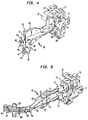
- Figs. 4 and 5 the guide 40 is shown as mounted to the aforementioned Arnett collar 70 which is symmetrical about a horizontal plane, thus allowing guide 40 to be mounted with the curved portion thereof curving in a first direction (Fig. 4) or in a second direction (Fig. 5).
- the collar has two cantilevered arms 71,71 spaced from the body thereof for mounting collar 70 in an aperture in a patch panel, and has openings 72,72 for receiving the detents 62,62 and mounting member 57.
- the teardrop shaped stop member 63,63 fits into the space between each of the cantilevered arms 71,71 and the body of collar 70 to prevent accidental depression of the arms, hence stop members 63,63 are not visible in Figs.
- each of flanges 66,66 fits against one edge of the arm 71, as seen in Figs. 4 and 5, thereby further anchoring member 57 in place and helping to ensure against inadvertent detachment of member 57 from collar 70.
- Fig. 5 also depicts a duplex SC coupler 72 mounted in collar 70 into which two SC connectors 73,73 are inserted. Extending from the rear of each of the connectors 73,73 is a single fiber 74,74, preferably coated with a protective coating or otherwise jacketed. As can be seen, fibers 74,74 follow the curved surface 42, being held in proximity thereto by fingers 52,53, T-shaped member 54, and fingers 44, 47, 48 and 49. Because there are two fibers to be guided, surface 42 has an enlarged area 65 for accommodating two fibers, as best seen in Fig. 5.
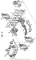
- Fig. 6 is a perspective exploded view of a patch panel assembly which includes a patch panel 76 having a plurality of apertures 77,77 therein.
- a fiber guide 11 is shown and is to be mounted to an adapter 78 containing a single SC coupler 79.
- a guide 40 mounted to a collar 81 such as disclosed in the aforementioned Arnett application Serial Number (Arnett 14) and, for illustrative purposes, also as disclosed in that application, a collar 82 and locking member 83.
- Also mounted to the panel 76 are cable or fiber guides 84,84 which are useful in organizing the fibers or cables and, mounted to a pair of such guides 84,84 is a fiber storage spool 86.
- the fiber guides 84 and the storage spool 86 are shown and described in the aforementioned U.S. patent application Serial Number (Arnett 13) of Jaime Arnett, filed concurrently herewith.
- optical fibers are the filamentary transmission media.
- Other types of transmission media of the filamentary nature might also, where desired, be guided, organized, and protected by the guide of the invention. Numerous changes or modifications to these embodiments, or other, similar embodiments may occur to workers in the art without departure from the spirit and scope thereof.
Landscapes
- Physics & Mathematics (AREA)
- General Physics & Mathematics (AREA)
- Optics & Photonics (AREA)
- Light Guides In General And Applications Therefor (AREA)
- Media Introduction/Drainage Providing Device (AREA)
Applications Claiming Priority (2)
| Application Number | Priority Date | Filing Date | Title |
|---|---|---|---|
| US395737 | 1995-02-28 | ||
| US08/395,737 US5530787A (en) | 1995-02-28 | 1995-02-28 | Optical fiber guide for preventing sharp bends |
Publications (2)
| Publication Number | Publication Date |
|---|---|
| EP0730176A2 true EP0730176A2 (de) | 1996-09-04 |
| EP0730176A3 EP0730176A3 (de) | 1997-01-08 |
Family
ID=23564289
Family Applications (1)
| Application Number | Title | Priority Date | Filing Date |
|---|---|---|---|
| EP96301294A Withdrawn EP0730176A3 (de) | 1995-02-28 | 1996-02-27 | Optische Faserführung |
Country Status (7)
| Country | Link |
|---|---|
| US (1) | US5530787A (de) |
| EP (1) | EP0730176A3 (de) |
| JP (1) | JPH08254622A (de) |
| KR (1) | KR960032026A (de) |
| AU (1) | AU4576696A (de) |
| CA (1) | CA2170438A1 (de) |
| TW (1) | TW310381B (de) |
Families Citing this family (61)
| Publication number | Priority date | Publication date | Assignee | Title |
|---|---|---|---|---|
| US5715348A (en) * | 1996-03-27 | 1998-02-03 | Next Level Communications | Fiber management system and method for routing optical fiber having a minimum bend radius |
| US5915056A (en) * | 1997-08-06 | 1999-06-22 | Lucent Technologies Inc. | Optical fiber strain relief device |
| US6049040A (en) * | 1997-09-17 | 2000-04-11 | Biles; Scott Douglas | Universal cable guide |
| US6002089A (en) * | 1997-09-26 | 1999-12-14 | The Wiremold Company | Non-linear raceway section having radial insert |
| US5920668A (en) * | 1997-10-24 | 1999-07-06 | Imra America, Inc. | Compact fiber laser unit |
| US5937131A (en) | 1997-11-17 | 1999-08-10 | Adc Telecommunications, Inc. | Optical cable exit trough |
| US6013875A (en) * | 1998-08-04 | 2000-01-11 | Fridenberg; Stephen J. | Transitional sleeving for coaxial cable |
| JP2000147269A (ja) * | 1998-09-01 | 2000-05-26 | Fujitsu Ltd | 電子装置 |
| US6134370A (en) * | 1998-10-30 | 2000-10-17 | Siecor Operations, Llc | Fiber optic cable guide |
| JP2000162446A (ja) * | 1998-11-30 | 2000-06-16 | Oki Electric Ind Co Ltd | 光ファイバ収納用具 |
| EP1006383A1 (de) * | 1998-12-04 | 2000-06-07 | Schroff GmbH | Führungs- und Halteelement |
| US6396989B1 (en) | 1999-02-19 | 2002-05-28 | Tyco Electronics Corporation | Fiber optic cable retainer assembly and clip with a bend-radius control surface |
| USD427897S (en) * | 1999-05-11 | 2000-07-11 | Ditel, Inc. | Fiber optic cable management clip |
| US6496642B2 (en) * | 1999-05-12 | 2002-12-17 | International Business Machines Corporation | Optical fiber cable routing guide |
| DE19950544A1 (de) * | 1999-10-20 | 2001-04-26 | Siemens Ag | Führungsbogen |
| KR100606659B1 (ko) * | 1999-12-02 | 2006-08-01 | 주식회사 케이티 | 패널부 광 점퍼 가이드 |
| US6356696B1 (en) | 2000-02-23 | 2002-03-12 | Delphi Technologies, Inc. | Radius control rod |
| WO2001079645A1 (en) * | 2000-04-14 | 2001-10-25 | Ren Judkins | Headrail for double shade |
| USD436027S1 (en) | 2000-06-05 | 2001-01-09 | Tyco Electronics Corporation | Cable retainer clip |
| US6438311B1 (en) | 2000-08-14 | 2002-08-20 | Oni Systems Corp. | Cable retainer and cable organizer using same |
| JP2002082231A (ja) * | 2000-09-11 | 2002-03-22 | Auto Network Gijutsu Kenkyusho:Kk | 光ファイバガイド装置 |
| US6535683B1 (en) | 2000-10-06 | 2003-03-18 | Adc Telecommunications, Inc. | Cable exit trough with cover |
| US6546181B1 (en) * | 2000-11-28 | 2003-04-08 | International Business Machines Corporation | Cable management device for mixed media |
| US6448495B1 (en) | 2001-01-12 | 2002-09-10 | Fiber Management Solutions, Inc. | Fiber optic cable raceway outlet with raceway cover, and method |
| US6601997B2 (en) | 2001-04-17 | 2003-08-05 | Fci Americas Technology, Inc. | Fiber optic cable guide boot |
| JP2002341182A (ja) * | 2001-05-14 | 2002-11-27 | Auto Network Gijutsu Kenkyusho:Kk | 光コネクタ |
| US6734435B2 (en) * | 2001-05-29 | 2004-05-11 | Rae Systems, Inc. | Photo-ionization detector and method for continuous operation and real-time self-cleaning |
| US6594435B2 (en) | 2001-06-26 | 2003-07-15 | Viasystems Group, Inc. | Bending an optical fiber into a backplane |
| US6629783B2 (en) | 2001-07-06 | 2003-10-07 | Fci Americas Technology, Inc. | Fiber optic cable guide boot |
| US6674951B1 (en) * | 2001-07-27 | 2004-01-06 | Ciena Corporation | Optical fiber management system and method and fiber bender thereof |
| JP2003149504A (ja) * | 2001-11-14 | 2003-05-21 | Auto Network Gijutsu Kenkyusho:Kk | 光コネクタ |
| US6604861B2 (en) * | 2002-03-28 | 2003-08-12 | Molex Incorporated | Cable management system for fiber optic connector assemblies |
| US20030236020A1 (en) * | 2002-06-19 | 2003-12-25 | Joseph Iamartino | Field installable, field adjustable angled boot for multi-conductor cables and process for installing the same |
| EP1391762B1 (de) * | 2002-08-16 | 2008-01-30 | Agilent Technologies, Inc. | Optische Verbindungsvorrichtung zum Koppeln von Verbindern an ein Gerät mit mehreren Anschlüssen |
| US6817780B2 (en) * | 2003-01-15 | 2004-11-16 | Fci Americas Technology, Inc. | Guide boot for a fiber-optic cable |
| EP2128673B1 (de) | 2004-03-08 | 2013-01-09 | ADC Telecommunications, Inc. | Glasfaseranschluss |
| US7706692B2 (en) * | 2004-09-29 | 2010-04-27 | Finisar Corporation | Consumer electronics with optical communication interface |
| US7548675B2 (en) * | 2004-09-29 | 2009-06-16 | Finisar Corporation | Optical cables for consumer electronics |
| US7489849B2 (en) | 2004-11-03 | 2009-02-10 | Adc Telecommunications, Inc. | Fiber drop terminal |
| US7729618B2 (en) * | 2005-08-30 | 2010-06-01 | Finisar Corporation | Optical networks for consumer electronics |
| US7860398B2 (en) | 2005-09-15 | 2010-12-28 | Finisar Corporation | Laser drivers for closed path optical cables |
| US7876989B2 (en) * | 2006-04-10 | 2011-01-25 | Finisar Corporation | Active optical cable with integrated power |
| US7712976B2 (en) | 2006-04-10 | 2010-05-11 | Finisar Corporation | Active optical cable with integrated retiming |
| US7445389B2 (en) * | 2006-04-10 | 2008-11-04 | Finisar Corporation | Active optical cable with integrated eye safety |
| US7401985B2 (en) * | 2006-04-10 | 2008-07-22 | Finisar Corporation | Electrical-optical active optical cable |
| US7778510B2 (en) * | 2006-04-10 | 2010-08-17 | Finisar Corporation | Active optical cable electrical connector |
| US8083417B2 (en) * | 2006-04-10 | 2011-12-27 | Finisar Corporation | Active optical cable electrical adaptor |
| US7499616B2 (en) * | 2006-04-10 | 2009-03-03 | Finisar Corporation | Active optical cable with electrical connector |
| US8070112B2 (en) * | 2007-01-19 | 2011-12-06 | Adc Telecommunications, Inc. | Lateral storage spool for overhead cable pathway |
| US8244124B2 (en) | 2007-04-30 | 2012-08-14 | Finisar Corporation | Eye safety mechanism for use in optical cable with electrical interfaces |
| US7903923B2 (en) * | 2007-10-09 | 2011-03-08 | Adc Telecommunications, Inc. | Drop terminal releasable engagement mechanism |
| US7860365B2 (en) * | 2007-11-16 | 2010-12-28 | Adc Telecommunications, Inc. | Edge protector for fiber optic cable routing |
| JP5090325B2 (ja) * | 2008-12-16 | 2012-12-05 | 富士通テレコムネットワークス株式会社 | 光ケーブルのガイド構造 |
| US8342755B2 (en) * | 2009-04-06 | 2013-01-01 | Adc Telecommunications, Inc. | Fiber optic connector and method for assembling |
| US8020813B1 (en) * | 2009-07-24 | 2011-09-20 | Cisco Technology, Inc. | Apparatus for routing cable across housing |
| US8993887B2 (en) * | 2009-11-09 | 2015-03-31 | L-Com, Inc. | Right angle twisted pair connector |
| US8424814B2 (en) | 2010-05-19 | 2013-04-23 | Panduit Corp. | Cable tray cable routing system |
| US10128647B2 (en) * | 2015-12-21 | 2018-11-13 | Te Connectivity Corporation | Cable management clasp |
| US10861623B2 (en) | 2016-02-26 | 2020-12-08 | RAN Technologies, Inc. | Modular wire management systems, apparatuses and methods |
| IT201700024029A1 (it) * | 2017-03-03 | 2018-09-03 | Kirmed Forniture Ospedaliere S R L | Dispositivo di bloccaggio |
| US10665368B2 (en) * | 2018-04-17 | 2020-05-26 | 3M Innovative Properties Company | Cable support |
Family Cites Families (12)
| Publication number | Priority date | Publication date | Assignee | Title |
|---|---|---|---|---|
| US4372511A (en) * | 1980-12-08 | 1983-02-08 | Bell Telephone Laboratories, Incorporated | Optical fiber cable strain relief assembly |
| US4934785A (en) * | 1983-08-29 | 1990-06-19 | American Telephone And Telegraph Company | Optical fiber connector |
| JPS60134205A (ja) * | 1983-12-23 | 1985-07-17 | Fujitsu Ltd | 光フアイバの保護方法 |
| US4652082A (en) * | 1984-10-29 | 1987-03-24 | Amp Incorporated | Angled electro optic connector |
| US5037175A (en) * | 1990-06-11 | 1991-08-06 | Amp Incorporated | Clip for dressing of fiber optic cable within confined space |
| US5073044A (en) * | 1990-10-31 | 1991-12-17 | Amp Incorporated | Right angle strain relief for optical fiber connector |
| US5233677A (en) * | 1992-02-27 | 1993-08-03 | Hughes Aircraft Company | Fiber optic package |
| US5212752A (en) * | 1992-05-27 | 1993-05-18 | At&T Bell Laboratories | Optical fiber ferrule connector having enhanced provisions for tuning |
| US5238426A (en) * | 1992-06-11 | 1993-08-24 | At&T Bell Laboratories | Universal patch panel for communications use in buildings |
| US5274729A (en) * | 1992-07-30 | 1993-12-28 | At&T Bell Laboratories | Universal optical fiber buildout system |
| US5347603A (en) * | 1993-06-14 | 1994-09-13 | Molex Incorporated | Right angle cable strain relief |
| US5419717A (en) * | 1994-08-15 | 1995-05-30 | The Whitaker Corporation | Hybrid connector between optics and edge card |
-
1995
- 1995-02-28 US US08/395,737 patent/US5530787A/en not_active Expired - Fee Related
-
1996
- 1996-02-26 TW TW085102158A patent/TW310381B/zh active
- 1996-02-27 CA CA002170438A patent/CA2170438A1/en not_active Abandoned
- 1996-02-27 EP EP96301294A patent/EP0730176A3/de not_active Withdrawn
- 1996-02-27 AU AU45766/96A patent/AU4576696A/en not_active Abandoned
- 1996-02-28 KR KR1019960005629A patent/KR960032026A/ko not_active Ceased
- 1996-02-28 JP JP8040912A patent/JPH08254622A/ja not_active Withdrawn
Also Published As
| Publication number | Publication date |
|---|---|
| KR960032026A (ko) | 1996-09-17 |
| JPH08254622A (ja) | 1996-10-01 |
| US5530787A (en) | 1996-06-25 |
| CA2170438A1 (en) | 1996-08-29 |
| AU4576696A (en) | 1996-09-05 |
| EP0730176A3 (de) | 1997-01-08 |
| TW310381B (de) | 1997-07-11 |
Similar Documents
| Publication | Publication Date | Title |
|---|---|---|
| US5530787A (en) | Optical fiber guide for preventing sharp bends | |
| US6134370A (en) | Fiber optic cable guide | |
| US6496638B1 (en) | Optical fiber cassette | |
| CA2111570C (en) | Termination equipment for an optical fibre cable | |
| US5625737A (en) | Optical fiber holder and method using same | |
| EP2439570B1 (de) | Modulares Stützsystem für Glasfaserplatten | |
| US6044194A (en) | Fiber optic cable bend radius control | |
| CA1329242C (en) | Termination module for use in an array of modules | |
| KR970003201B1 (ko) | 광섬유 연결기 | |
| US5987203A (en) | Distribution module for optical couplings | |
| EP2249581B1 (de) | Glasfasersystem mit rückwärtigen Steckverbindern | |
| US4962989A (en) | Clamping apparatus for an array of optical fiber filaments | |
| US6249635B1 (en) | Universal fiber optic splice holder | |
| KR19980703324A (ko) | 광섬유 스플라이스 구조체 | |
| US20230085572A1 (en) | Optical fiber management trays and assemblies with features for improved rollable fiber ribbon routing | |
| US20040121646A1 (en) | Modified, field installable, field adjustable flexible angled boot for multi-conductor cables and process for installing the same | |
| EP1181605B1 (de) | Kabelendstück | |
| MXPA02006587A (es) | Funda guia para cable de fibra optica. | |
| EP0646811A2 (de) | Abzweigung für optische Fasern | |
| EP1407305B1 (de) | Verteiler für optisches faserbändchen | |
| KR100890688B1 (ko) | 광섬유 단자 유니트 | |
| EP0137667B1 (de) | Halter für optische Fibern | |
| EP3662312B1 (de) | Optischer verteilerkasten | |
| US20260126607A1 (en) | Chip for fiber demarcation box | |
| GB2283373A (en) | Breakout |
Legal Events
| Date | Code | Title | Description |
|---|---|---|---|
| PUAI | Public reference made under article 153(3) epc to a published international application that has entered the european phase |
Free format text: ORIGINAL CODE: 0009012 |
|
| AK | Designated contracting states |
Kind code of ref document: A2 Designated state(s): DE FR GB |
|
| PUAL | Search report despatched |
Free format text: ORIGINAL CODE: 0009013 |
|
| AK | Designated contracting states |
Kind code of ref document: A3 Designated state(s): DE FR GB |
|
| 17P | Request for examination filed |
Effective date: 19970625 |
|
| STAA | Information on the status of an ep patent application or granted ep patent |
Free format text: STATUS: THE APPLICATION HAS BEEN WITHDRAWN |
|
| 18W | Application withdrawn |
Withdrawal date: 19971028 |