EP0730183A2 - Système optique, dispositif d'observation d'image et appareil de prise de vue l'utilisant - Google Patents
Système optique, dispositif d'observation d'image et appareil de prise de vue l'utilisant Download PDFInfo
- Publication number
- EP0730183A2 EP0730183A2 EP96102913A EP96102913A EP0730183A2 EP 0730183 A2 EP0730183 A2 EP 0730183A2 EP 96102913 A EP96102913 A EP 96102913A EP 96102913 A EP96102913 A EP 96102913A EP 0730183 A2 EP0730183 A2 EP 0730183A2
- Authority
- EP
- European Patent Office
- Prior art keywords
- plane
- optical system
- image
- rays
- local power
- Prior art date
- Legal status (The legal status is an assumption and is not a legal conclusion. Google has not performed a legal analysis and makes no representation as to the accuracy of the status listed.)
- Granted
Links
Images






Classifications
-
- G—PHYSICS
- G02—OPTICS
- G02B—OPTICAL ELEMENTS, SYSTEMS OR APPARATUS
- G02B27/00—Optical systems or apparatus not provided for by any of the groups G02B1/00 - G02B26/00, G02B30/00
-
- G—PHYSICS
- G02—OPTICS
- G02B—OPTICAL ELEMENTS, SYSTEMS OR APPARATUS
- G02B17/00—Systems with reflecting surfaces, with or without refracting elements
- G02B17/08—Catadioptric systems
- G02B17/0856—Catadioptric systems comprising a refractive element with a reflective surface, the reflection taking place inside the element, e.g. Mangin mirrors
- G02B17/086—Catadioptric systems comprising a refractive element with a reflective surface, the reflection taking place inside the element, e.g. Mangin mirrors wherein the system is made of a single block of optical material, e.g. solid catadioptric systems
-
- G—PHYSICS
- G02—OPTICS
- G02B—OPTICAL ELEMENTS, SYSTEMS OR APPARATUS
- G02B13/00—Optical objectives specially designed for the purposes specified below
- G02B13/22—Telecentric objectives or lens systems
-
- G—PHYSICS
- G02—OPTICS
- G02B—OPTICAL ELEMENTS, SYSTEMS OR APPARATUS
- G02B17/00—Systems with reflecting surfaces, with or without refracting elements
- G02B17/02—Catoptric systems, e.g. image erecting and reversing system
- G02B17/06—Catoptric systems, e.g. image erecting and reversing system using mirrors only, i.e. having only one curved mirror
- G02B17/0605—Catoptric systems, e.g. image erecting and reversing system using mirrors only, i.e. having only one curved mirror using two curved mirrors
- G02B17/0621—Catoptric systems, e.g. image erecting and reversing system using mirrors only, i.e. having only one curved mirror using two curved mirrors off-axis or unobscured systems in which not all of the mirrors share a common axis of rotational symmetry, e.g. at least one of the mirrors is warped, tilted or decentered with respect to the other elements
-
- G—PHYSICS
- G02—OPTICS
- G02B—OPTICAL ELEMENTS, SYSTEMS OR APPARATUS
- G02B17/00—Systems with reflecting surfaces, with or without refracting elements
- G02B17/08—Catadioptric systems
- G02B17/0804—Catadioptric systems using two curved mirrors
- G02B17/0816—Catadioptric systems using two curved mirrors off-axis or unobscured systems in which not all of the mirrors share a common axis of rotational symmetry, e.g. at least one of the mirrors is warped, tilted or decentered with respect to the other elements
-
- G—PHYSICS
- G02—OPTICS
- G02B—OPTICAL ELEMENTS, SYSTEMS OR APPARATUS
- G02B23/00—Telescopes, e.g. binoculars; Periscopes; Instruments for viewing the inside of hollow bodies; Viewfinders; Optical aiming or sighting devices
- G02B23/14—Viewfinders
-
- G—PHYSICS
- G02—OPTICS
- G02B—OPTICAL ELEMENTS, SYSTEMS OR APPARATUS
- G02B27/00—Optical systems or apparatus not provided for by any of the groups G02B1/00 - G02B26/00, G02B30/00
- G02B27/01—Head-up displays
- G02B27/017—Head mounted
- G02B27/0172—Head mounted characterised by optical features
-
- G—PHYSICS
- G02—OPTICS
- G02B—OPTICAL ELEMENTS, SYSTEMS OR APPARATUS
- G02B27/00—Optical systems or apparatus not provided for by any of the groups G02B1/00 - G02B26/00, G02B30/00
- G02B27/01—Head-up displays
- G02B27/0101—Head-up displays characterised by optical features
- G02B2027/011—Head-up displays characterised by optical features comprising device for correcting geometrical aberrations, distortion
-
- G—PHYSICS
- G02—OPTICS
- G02B—OPTICAL ELEMENTS, SYSTEMS OR APPARATUS
- G02B27/00—Optical systems or apparatus not provided for by any of the groups G02B1/00 - G02B26/00, G02B30/00
- G02B27/01—Head-up displays
- G02B27/0101—Head-up displays characterised by optical features
- G02B2027/0138—Head-up displays characterised by optical features comprising image capture systems, e.g. camera
Definitions
- the present invention relates to an optical system, and more particularly, to an optical system suitable for applications in image observing apparatus such as a finder of camera and a so-called head-mounted display and in image pickup apparatus such as cameras.
- Japanese Laid-open Patent Application No. 58-78116 discloses an optical apparatus for observing an object image on a primary image plane, obtained by a photographing optical system, through an optical element in a prism shape having a concave, spherical, reflecting surface set as inclined to the observer's eye.
- the reflecting surface is an inclined spherical surface in this conventional example, it is difficult to correct well for optical aberrations including astigmatism, occurring there.
- the official gazette of the above application describes a need to add a new lens system for improving correction for the aberrations.
- Japanese Laid-open Patent Application No. 5-303055 discloses an optical system having an additional lens system (relay lens system) of this type. Addition of such a relay lens system, however, lengthens the total length of the optical system, resulting in a defect of spoiling compactification of the optical system.
- Japanese Laid-open Patent Applications No. 5-303054, No. 5-303056, and No. 5-323229 disclose optical systems in which one reflecting surface out of the following surfaces is inclined relative to the optical axis of the observer's eye in order to improve compactification and aberrations of optical system: normal aspherical surfaces of revolution having high-order aspherical terms; paraboloids and ellipsoids of revolution given by conical functions, each defined by a conical coefficient; toric aspherical surfaces (or anamorphic aspherical surfaces), each expressed by mutually different aspherical functions on orthogonal coordinate axes.
- a desired method for focusing (diopter adjustment) of the so-called decentering optical system with the inclined reflecting surface is to move the focal plane of the optical system (an image display device or an image pickup device), because moving the optical system causes a great change of optical performance.
- a desired optical system is telecentric with respect to the focal plane.
- the optical system in Japanese Laid-open Patent Application No. 5-303056 is corrected for astigmatism and distortion, but still has curvature of field left without being corrected for.
- the optical system in Japanese Laid-open Patent Application No. 5-323229 is corrected for curvature of field, astigmatism, and distortion, but it has angles of rays largely inclined relative to the focal plane, which, in the case of a display device such as a liquid crystal panel or an image pickup device such as a CCD being located on the focal plane, causes a defect of greatly degrading the performance because of an angle dependence of characteristics of the device.
- Japanese Laid-open Patent Application No. 3-180810 discloses increasing the F-number for the optical system by setting the view point of observer away and arranging the optical system in such a manner that curvature of field and astigmatism are corrected by increasing the depth of focus of the optical system and that distortion distortion is corrected by an aspherical surface having a cross term (e.g., xy) in the orthogonal coordinate system (x, y, z).
- a cross term e.g., xy
- this optical system is based on the method for observing an image from the view point set away, it does not permit, however, wider-angle arrangement or larger-screen arrangement.
- the optical system was arranged in the telephoto type in combination of a convex mirror with a concave mirror, it had a defect of the large size as a whole against compactification.
- An object of the present invention is to provide an optical system formed in a very simple arrangement and well corrected for the various aberrations.
- An optical system of the present invention has a first surface and a second surface, each surface being symmetric with respect to only one symmetry plane, wherein the first surface is a reflecting concave surface, which is inclined to a reference axial ray present in the symmetry plane, and wherein a local power of the second surface changes from a positive to a negative.
- the local power of the second surface as to rays in the symmetry plane and/or the local power of the second surface as to rays in a plane being perpendicular to the symmetry plane and including the reference axial ray and in a plane parallel to the foregoing plane changes from a positive to a negative along a cut line where the symmetry plane cuts the second surface.
- the local power of the second surface preferably changes from a positive to a negative along the cut line in a direction of from a shorter optical pathlength to a longer optical pathlength between the first surface and the second surface.
- Image observing apparatus and image pickup apparatus of the present invention are characterized by using the optical system of the present invention.
- S represents a stop
- S1 a first reflecting surface (optically acting surface)
- S2 a second reflecting surface (optically acting surface)
- P is a focal plane.
- the optical system when applied to an actual image observing optical system, is arranged as a system in which the light originates from the focal plane P (image display device) to be incident to the stop S (the pupil of observer).
- a reference axial ray Lo as a ray emerging from the center of the stop S and impinging on the center P o of the focal plane P nearly normally thereto.
- principal rays L are rays emerging from the center of the stop S and impinging upon respective points on the focal plane P nearly normally thereto.
- the first reflecting surface S1 is determined in such a shape that the principal rays L from the stop S become approximately telecentric toward the image side after reflected by the first reflecting surface S1 and that an average image plane is nearly superimposed on a plane H perpendicular to the reference axial ray Lo.
- the average image plane is a plane including intermediate points between image positions of the rays in the respective cross sections.
- points Me are image points of the rays in the Y-Z cross section
- points Sa are image points of the rays in the X-Z cross section.
- middle points Q between the points Me and the points Sa in the principal rays L are points on the average image plane, and differences between the points Me and the points Sa are astigmatism.
- Telecentricity of principal rays and distortion are affected by the total shape of reflecting surface, and an imaging state of each beam (curvature of field, astigmatism) is affected by the local shape of surface.
- the first reflecting surface S1 is mainly arranged to maintain telecentricity of principal rays and correct for distortion and to align the average image plane with the plane H, and the second reflecting surface S2 corrects for remaining astigmatism.
- the second reflecting surface S2 is formed in such a shape as to mainly correct for astigmatism of beam, as shown in Fig. 2.
- the shape can be determined in such a manner that local image magnifications of rays in the Y-Z cross section increase from the near side (A) with respect to the first reflecting surface S1 toward the far side (B) and that local image magnifications of rays in the X-Z cross section decrease from the near side (A) with respect to the first reflecting surface toward the far side (B).
- a magnification of a local surface is a ratio b''/b' of an image distance b'' to an object distance b' of the outstanding surface, as shown in Fig. 2.
- the two reflecting surfaces having the shapes as described herein can correct for distortion, curvature of field, and astigmatism and maintain telecentricity. If a third optically acting surface S3 (not shown) is placed near the focal plane between the second reflecting surface S2 and the focal plane P, the optical system can be corrected for slight distortion and deviation of telecentricity caused by the shape of the second reflecting surface S2, thus further improving partial changes of the image plane.
- the third optically acting surface S3 may be either a refracting surface or a reflecting surface.
- the third optically acting surface S3 can decrease overlap of beams reaching the respective points (image points) on the focal plane P and it enables partial correction of image points by a partial change of shape of surface, thereby readily correcting for aberrations that the first reflecting surface S1 and the second reflecting surface S2 as described above fail to correct for.
- the optical system of the present invention can be realized by a single optical element, which is very advantageous in compactification and reduction of cost.
- Figs. 3A and 3B are schematic drawings to show the major part of Embodiment 1 of the image observing apparatus according to the present invention.
- B1 is an optical element, which has the first, the second, and the third optically acting surfaces S1, S2, S3. Each of the three acting surfaces is formed in a shape symmetric with respect to only one plane (the YZ plane).
- S represents a desired pupil position of observer, and P a display surface of an image display device.
- the third optically acting surface S3 is shaped in an aspherical surface symmetric with respect to only the symmetry plane, and is located nearly perpendicular to the reference axial ray Lo emerging from the center of the display surface P nearly normally to the display surface P.
- the second optically acting surface S2 is shaped in an aspherical surface symmetric with respect to only the symmetry plane, and is located as inclined at such an angle as to totally reflect the reference axial ray Lo refracted by the third optically acting surface S3.
- the first optically acting surface S1 is an aspherical reflecting surface (obtained by depositing a reflecting film on a surface) of a totally strong concave surface which is symmetric with respect to only the symmetry plane, and is located as inclined relative to the reference axial ray Lo totally reflected by the second optically acting surface S2.
- the reference axial ray Lo reflected by the first optically acting surface S1 passes through the second optically acting surface S2 to reach the pupil S.
- a light beam emerging from an image displayed on the display surface P first travels through the third optically acting surface S3 toward the second optically acting surface S2 and is then totally reflected by the surface S2 toward the first optically acting surface S1. Then the beam is reflected by the surface S1 to become a converging beam, and the beam travels again to the second optically acting surface S2. The beam passes through this surface S2 this time to form a virtual image of the image and to reach the observer's pupil S, whereby the observer can visually recognize the virtual image.
- Fig. 18 is an explanatory drawing of the absolute coordinate system and local coordinate systems. This is next explained.
- the origin of the absolute coordinate system is set at the center O of the desired pupil position S of observer, and the Z-axis is a straight line perpendicular to the pupil plane through the point O, as located on the symmetry plane.
- the Y-axis is a straight line making an angle of 90° counterclockwise relative to the Z-axis on the symmetry plane and through the origin O.
- the X-axis is a straight line perpendicular to the Y- and Z-axes through the origin O.
- the Z-axis is superimposed on the reference axial ray Lo coming from the center of the display surface P of the image display device nearly normally to the display surface P to reach the center of the pupil S.
- the origin Oi of each local coordinate system is set at absolute coordinates (SXi, SYi, SZi).
- the z-axis of each local coordinate system is a straight line passing through the origin Oi in the YZ plane and making an angle Ai with the Z-axis of the absolute coordinate system.
- the y-axis is a straight line passing through the origin Oi and making an angle of 90° counterclockwise relative to the z-axis on the symmetry plane.
- the x-axis is a straight line passing through the origin Oi and being perpendicular to the y-axis and the z-axis.
- each surface is expressed by local coordinates.
- Each of the shapes of the optically acting surfaces in each embodiment of the present invention is a shape as defined by the following function, having a conical function defined by the conical coefficient, and Zernike polynomials.
- z c(x 2 + y 2 )/[1 + ⁇ 1 - (1 + k)c 2 (x 2 + y 2 ) ⁇ 1/2 ] + c 1 (x 2 - y 2 ) + c 2 (-1 + 2x 2 + 2y 2 ) + c 3 (-2y + 3x 2 y + 3y 3 ) + c 4 (3x 2 y - y 3 ) + c 5 (x 4 - 6x 2 y 2 + y 4 ) + c 6 (-3x 2 + 4x 4 + 3y 2 - 4y 4 ) + c 7 (1 - 6x 2 + 6x 4 - 6y 2 + 12x 2 y 2 + 6y 4 ) + c 8 (3y
- k is the conical coefficient of each surface
- c j is an aspherical coefficient of the j-th Zernike polynomial in each surface.
- Table 1 shows data for the arrangement of Embodiment 1.
- Table 2 includes local radii of curvature r Lx and r Ly of the second optically acting surface S2 as expressed at six points on the acting surface. Coordinates in the table are local coordinates of the surface.
- Figs. 19A and 19B are explanatory drawings of the local radii of curvature r Lx and r Ly .
- the local radius of curvature r Lx or r Ly takes a negative value when the optically acting surface is concave on the light incidence side.
- ⁇ Ly -2N/r Ly with the local radius of curvature r Ly and the refractive index N of the medium in which the light travels.
- Figs. 4A to 4D are aberration diagrams of Embodiment 1.
- the aberration diagrams indicate lateral aberrations at the image point on the reference axial ray Lo, the image points of ⁇ in the y-direction to the reference axial ray Lo, and the image point of + ⁇ in the x-direction relative to the reference axial ray Lo.
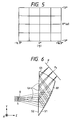
- Fig. 5 shows distortion of an image of a grid object when ray trace from the pupil S to the display surface P is carried out in the image observing apparatus of the present embodiment.
- Supposing distortion of the image on the display surface P is pincushion distortion and if the ray trace is carried out from the display surface P to the pupil S for the optical system, distortion of image becomes of a barrel form in an opposite shape.
- Fig. 6 is a schematic drawing to show the major part of Embodiment 2 of the image observing apparatus according to the present invention.
- the present embodiment has a shorter focal length of the total system than Embodiment 1 has, thereby achieving a wider-angle arrangement.
- Table 3 shows data for the arrangement of Embodiment 2.
- Table 4 includes the local radii of curvature r L of the second optically acting surface S2 of the present embodiment at six points on the acting surface.
- Figs. 7A, 7B, 7C, and 7D are aberration diagrams of Embodiment 2.
- the aberration diagrams indicate lateral aberrations at the image point on the reference axial ray Lo, the image points of ⁇ in the y-direction relative to the reference axial ray Lo, and the image point of + ⁇ in the x-direction relative to the reference axial ray Lo.
- Fig. 8 shows distortion of an image of the grid object when the ray trace is carried out from the pupil S to the display surface P in the present embodiment.
- Fig. 9 is a schematic drawing to show the major part of Embodiment 3 of the present invention.
- the present embodiment has a higher refractive index of the optical element B1 than Embodiment 1 has.
- Table 5 shows data for the arrangement of Embodiment 3.
- Table 6 includes the local radii of curvature r L of the second optically acting surface S2 of the present embodiment at six points on the acting surface.
- Figs. 10A, 10B, 10C, and 10D are aberration diagrams of Embodiment 3.
- the aberration diagrams indicate lateral aberrations at the image point on the reference axial ray Lo, the image points of ⁇ in the y-direction relative to the reference axial ray Lo, and the image point of + ⁇ in the x-direction relative to the reference axial ray Lo.
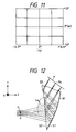
- Fig. 11 shows distortion of an image of the grid object when the ray trace is carried out from the pupil S to the display surface P in Embodiment 3.
- Fig. 12 is a schematic drawing to show the major part of Embodiment 4 of the image observing apparatus of the present invention.
- the present embodiment is a so-called anamorphic optical system in which the focal length fx in the z-x plane is set to be different from the focal length fy in the z-y plane.
- Table 7 shows data for the arrangement of the present embodiment.
- Table 8 includes the local radii of curvature r L of the second optically acting surface S2 of the present embodiment at six points on the acting surface.
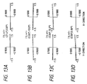
- Figs. 13A, 13B, 13C, and 13D are aberration diagrams of Embodiment 4.
- the aberration diagrams indicate lateral aberrations at the image point on the reference axial ray Lo, the image points of ⁇ in the y-direction relative to the reference axial ray Lo, and the image point of + ⁇ in the x-direction relative to the reference axial ray Lo.
- Fig. 14 shows distortion of an image of the grid object when the ray trace is carried out from the pupil S to the display surface P in Embodiment 4. Since the focal length fx in the z-x plane is shorter than the focal length fy in the z-y plane, a virtual image of the image displayed on the display surface P is expanded 1.32 times larger in the x-direction than in the y-direction.
- Fig. 15 is a schematic drawing to show the major part of Embodiment 5 of the image observing apparatus according to the present invention.
- the present embodiment has an arrangement different from those of the previous embodiments, and is arranged in such a manner that the optical system is composed of a first member C1 and a second member C2, the first member C1 has a first reflecting surface (first optically acting surface) S1 of an aspherical surface symmetric with respect to only one symmetry plane, and the surface is set as inclined relative to the reference axial ray Lo.
- the second member C2 has a second reflecting surface (second optically acting surface) S2 of an aspherical surface symmetric with respect to only the symmetry plane, and the surface is set as inclined relative to the reference axial ray Lo reflected by the first reflecting surface S1.
- a light beam emerging from the image displayed on the display surface P of the image display device is reflected by the second reflecting surface S2 toward the first reflecting surface S1. Then the light beam is reflected and converged by this surface S1 to form an enlarged, virtual image of the image and to be incident to the pupil S of observer, whereby the observer can visually recognize the enlarged, virtual image of the image.
- Table 9 shows data for the arrangement of the present embodiment.
- Table 10 indicates local powers of the second optically acting surface S2 of the present embodiment at six points on the acting surface.
- Figs. 16A, 16B, 16C, and 16D are aberration diagrams of Embodiment 5.
- the aberration diagrams indicate lateral aberrations at the image point on the reference axial ray Lo, the image points of ⁇ in the y-direction relative to the reference axial ray Lo, and the image point of + ⁇ in the x-direction relative to the reference axial ray Lo.
- Fig. 17 shows distortion of an image of the grid object when the ray trace is carried out from the pupil S to the display surface P in Embodiment 5.
- the present embodiment obtains the optical system arranged in a particularly simple structure, which is well corrected for distortion, curvature of field, and astigmatism, and which almost satisfies the telecentric condition to the display surface.
- an image pickup apparatus can also be constructed by setting the stop S' at the position of the pupil S and setting a recording surface of an image pickup means or a photoelectric conversion element R such as a CCD in place of the display surface P of the image display device, as shown in Figs. 20A and 20B.
- This arrangement can achieve the image pickup apparatus well corrected for the various aberrations and satisfying the telecentric condition to the image pickup surface at a wide angle.
- the present invention can achieve the optical system having a simple structure and demonstrating good optical performance, based on the above arrangements.
- the optical system can be constructed in a single optical element, which permits a high-performance optical system to be manufactured at low cost.
- the present invention relates to an optical system apparatus, which has a first surface symmetric with respect to only one symmetry plane and a second surface symmetric with respect to only the symmetry plane, in which the first plane is a reflective, concave surface and is inclined relative to a reference axial ray present in the symmetry plane. Further, a local power of the second surface changes from a positive to a negative.
Landscapes
- Physics & Mathematics (AREA)
- General Physics & Mathematics (AREA)
- Optics & Photonics (AREA)
- Astronomy & Astrophysics (AREA)
- Lenses (AREA)
Applications Claiming Priority (3)
| Application Number | Priority Date | Filing Date | Title |
|---|---|---|---|
| JP06699595A JP3658034B2 (ja) | 1995-02-28 | 1995-02-28 | 画像観察光学系及び撮像光学系 |
| JP6699595 | 1995-02-28 | ||
| JP66995/95 | 1995-02-28 |
Publications (3)
| Publication Number | Publication Date |
|---|---|
| EP0730183A2 true EP0730183A2 (fr) | 1996-09-04 |
| EP0730183A3 EP0730183A3 (fr) | 1998-05-06 |
| EP0730183B1 EP0730183B1 (fr) | 2001-12-19 |
Family
ID=13332106
Family Applications (1)
| Application Number | Title | Priority Date | Filing Date |
|---|---|---|---|
| EP96102913A Expired - Lifetime EP0730183B1 (fr) | 1995-02-28 | 1996-02-27 | Système optique, dispositif d'observation d'image et appareil de prise de vue l'utilisant |
Country Status (5)
| Country | Link |
|---|---|
| US (1) | US5706136A (fr) |
| EP (1) | EP0730183B1 (fr) |
| JP (1) | JP3658034B2 (fr) |
| KR (1) | KR100249965B1 (fr) |
| DE (1) | DE69618046T2 (fr) |
Cited By (17)
| Publication number | Priority date | Publication date | Assignee | Title |
|---|---|---|---|---|
| EP0845692A3 (fr) * | 1996-11-27 | 1998-08-19 | Olympus Optical Co., Ltd. | Système optique avec une surface courbée asymètrique en rotation |
| US5812323A (en) * | 1995-08-21 | 1998-09-22 | Olympus Optical Co., Ltd. | Image display apparatus |
| US5886824A (en) * | 1996-08-30 | 1999-03-23 | Olympus Optical Co., Ltd. | Image display apparatus |
| EP0857992A3 (fr) * | 1997-02-07 | 1999-06-09 | Olympus Optical Co., Ltd. | Système optique à prisme décentré |
| US5917656A (en) * | 1996-11-05 | 1999-06-29 | Olympus Optical Co., Ltd. | Decentered optical system |
| US5986812A (en) * | 1996-07-19 | 1999-11-16 | Olympus Optical Co. Ltd. | Image display apparatus |
| US6097542A (en) * | 1996-10-16 | 2000-08-01 | Olympus Optical Co., Ltd. | Optical system having reflecting surface of non-rotationally symmetric surface configuration |
| US6097354A (en) * | 1997-05-27 | 2000-08-01 | Olympus Optical Co., Ltd. | Image display apparatus |
| US6104539A (en) * | 1997-04-08 | 2000-08-15 | Olympus Optical Co., Ltd. | Decentered prism optical system |
| US6104540A (en) * | 1996-11-05 | 2000-08-15 | Olympus Optical Co., Ltd. | Decentered optical system |
| WO2000048033A1 (fr) * | 1999-02-10 | 2000-08-17 | Matsushita Electric Industrial Co., Ltd. | Dispositif optique reflecteur, dispositif optique reflecteur a semi-conducteur, dispositif d'imagerie comportant ceux-ci, dispositif d'imagerie a longueurs d'ondes multiples, camera video et dispositif de surveillance monte sur un vehicule |
| FR2792174A1 (fr) * | 1999-04-16 | 2000-10-20 | Sextant Avionique | Visiere pour casque |
| US6178052B1 (en) | 1996-12-27 | 2001-01-23 | Olympus Optical Co., Ltd. | Finder optical system |
| US6633337B1 (en) | 1997-01-31 | 2003-10-14 | Olympus Optical Co., Ltd. | Electronic camera |
| US6760169B2 (en) | 1997-05-07 | 2004-07-06 | Olympus Corporation | Prism optical element, image observation apparatus and image display apparatus |
| US6929373B2 (en) | 2001-04-11 | 2005-08-16 | Matsushita Electric Industrial Co., Ltd. | Reflection optical device and imaging apparatus comprising it, multi-wavelength imaging apparatus, and vehicle mounted monitor |
| CN102692709A (zh) * | 2012-06-15 | 2012-09-26 | 中航华东光电有限公司 | 基于球面棱镜的头戴显示器的光学系统 |
Families Citing this family (105)
| Publication number | Priority date | Publication date | Assignee | Title |
|---|---|---|---|---|
| JP3720464B2 (ja) * | 1995-07-03 | 2005-11-30 | キヤノン株式会社 | 光学素子及びそれを用いた観察系 |
| JP3666953B2 (ja) * | 1995-09-27 | 2005-06-29 | キヤノン株式会社 | 光学素子 |
| JPH09211331A (ja) * | 1996-01-29 | 1997-08-15 | Canon Inc | 反射光学系 |
| JPH09211330A (ja) * | 1996-01-29 | 1997-08-15 | Canon Inc | 反射光学系 |
| JP3761957B2 (ja) * | 1996-02-15 | 2006-03-29 | キヤノン株式会社 | 反射型の光学系及びそれを用いた撮像装置 |
| US5959780A (en) * | 1996-04-15 | 1999-09-28 | Olympus Optical Co., Ltd. | Head-mounted display apparatus comprising a rotationally asymmetric surface |
| US6208468B1 (en) | 1996-06-11 | 2001-03-27 | Olympus Optical Co., Ltd. | Image-forming optical system and apparatus using the same |
| US6128144A (en) | 1996-12-02 | 2000-10-03 | Olympus Optical Co., Ltd. | Optical system for camera and camera apparatus |
| JPH10239630A (ja) * | 1996-12-24 | 1998-09-11 | Olympus Optical Co Ltd | 画像表示装置 |
| JP3865906B2 (ja) | 1997-06-27 | 2007-01-10 | オリンパス株式会社 | 画像表示装置 |
| JPH11194295A (ja) | 1997-11-06 | 1999-07-21 | Olympus Optical Co Ltd | 光学系 |
| JPH11142783A (ja) * | 1997-11-12 | 1999-05-28 | Olympus Optical Co Ltd | 画像表示装置 |
| JP3645698B2 (ja) | 1997-11-17 | 2005-05-11 | オリンパス株式会社 | 光学プリズム、鏡枠および光学アッセンブリ |
| JP3929153B2 (ja) * | 1998-01-07 | 2007-06-13 | オリンパス株式会社 | 結像光学系 |
| JP4198784B2 (ja) | 1998-05-22 | 2008-12-17 | オリンパス株式会社 | 光学プリズム、鏡枠及び光学アッセンブリ |
| JP2000098234A (ja) | 1998-06-19 | 2000-04-07 | Canon Inc | 光学系及びそれを用いる画像観察装置 |
| JP2000098293A (ja) | 1998-06-19 | 2000-04-07 | Canon Inc | 画像観察装置 |
| JP2000056362A (ja) * | 1998-08-05 | 2000-02-25 | Canon Inc | ファインダー光学系 |
| JP2000137166A (ja) | 1998-10-30 | 2000-05-16 | Canon Inc | 光学系 |
| EP1465003B1 (fr) | 1999-04-02 | 2008-12-31 | Olympus Corporation | Système optique de visualisation et afficheur d'image contenant ce système |
| US6147807A (en) * | 1999-05-04 | 2000-11-14 | Honeywell, Inc. | High brightness see-through head-mounted display |
| JP2001188194A (ja) * | 1999-10-20 | 2001-07-10 | Shimadzu Corp | 表示装置 |
| JP2001249301A (ja) | 2000-03-03 | 2001-09-14 | Olympus Optical Co Ltd | 観察光学系及びそれを用いた画像表示装置 |
| JP2001311904A (ja) | 2000-04-28 | 2001-11-09 | Canon Inc | 画像表示装置および画像表示システム |
| US6710927B2 (en) * | 2000-06-26 | 2004-03-23 | Angus Duncan Richards | Multi-mode display device |
| JP4727025B2 (ja) * | 2000-08-01 | 2011-07-20 | オリンパス株式会社 | 画像表示装置 |
| JP4646374B2 (ja) * | 2000-09-29 | 2011-03-09 | オリンパス株式会社 | 画像観察光学系 |
| GB0029340D0 (en) * | 2000-11-30 | 2001-01-17 | Cambridge 3D Display Ltd | Flat panel camera |
| JP2002221688A (ja) * | 2001-01-29 | 2002-08-09 | Olympus Optical Co Ltd | 光学系 |
| US6791760B2 (en) | 2001-07-24 | 2004-09-14 | Itt Manufacturing Enterprises, Inc. | Planar diffractive relay |
| CN100367074C (zh) * | 2003-10-27 | 2008-02-06 | 深圳国际技术创新研究院 | 眼镜式显示器 |
| GB0522968D0 (en) | 2005-11-11 | 2005-12-21 | Popovich Milan M | Holographic illumination device |
| GB0718706D0 (en) | 2007-09-25 | 2007-11-07 | Creative Physics Ltd | Method and apparatus for reducing laser speckle |
| CA2712059A1 (fr) | 2008-01-22 | 2009-07-30 | The Arizona Board Of Regents On Behalf Of The University Of Arizona | Visiocasque de projection utilisant des micro-dispositifs d'affichage reflechissants |
| WO2010123934A1 (fr) | 2009-04-20 | 2010-10-28 | The Arizona Board Of Regents On Behalf Of The University Of Arizona | Visiocasque sans forme à transparence optique |
| US9335604B2 (en) | 2013-12-11 | 2016-05-10 | Milan Momcilo Popovich | Holographic waveguide display |
| US11726332B2 (en) | 2009-04-27 | 2023-08-15 | Digilens Inc. | Diffractive projection apparatus |
| US20110075257A1 (en) | 2009-09-14 | 2011-03-31 | The Arizona Board Of Regents On Behalf Of The University Of Arizona | 3-Dimensional electro-optical see-through displays |
| US11204540B2 (en) | 2009-10-09 | 2021-12-21 | Digilens Inc. | Diffractive waveguide providing a retinal image |
| US20200057353A1 (en) | 2009-10-09 | 2020-02-20 | Digilens Inc. | Compact Edge Illuminated Diffractive Display |
| US8125716B2 (en) * | 2009-10-14 | 2012-02-28 | The United States Of America As Represented By The Secretary Of The Army | Near eye display prism optic assembly |
| KR20120088754A (ko) | 2009-11-21 | 2012-08-08 | 더글라스 피터 마기아리 | 헤드 마운티드 디스플레이 장치 |
| CN102782562B (zh) | 2010-04-30 | 2015-07-22 | 北京理工大学 | 宽视场高分辨率拼接式头盔显示装置 |
| CN102053368A (zh) * | 2010-08-27 | 2011-05-11 | 中国科学院长春光学精密机械与物理研究所 | 头戴式显示系统 |
| JP5809168B2 (ja) | 2010-12-20 | 2015-11-10 | 富士フイルム株式会社 | ビューファインダおよびカメラ |
| NZ706893A (en) | 2010-12-24 | 2017-02-24 | Magic Leap Inc | An ergonomic head mounted display device and optical system |
| US9274349B2 (en) | 2011-04-07 | 2016-03-01 | Digilens Inc. | Laser despeckler based on angular diversity |
| EP2748670B1 (fr) | 2011-08-24 | 2015-11-18 | Rockwell Collins, Inc. | Affichage de données portable |
| US10670876B2 (en) | 2011-08-24 | 2020-06-02 | Digilens Inc. | Waveguide laser illuminator incorporating a despeckler |
| WO2016020630A2 (fr) | 2014-08-08 | 2016-02-11 | Milan Momcilo Popovich | Illuminateur laser en guide d'ondes comprenant un dispositif de déchatoiement |
| US20150010265A1 (en) | 2012-01-06 | 2015-01-08 | Milan, Momcilo POPOVICH | Contact image sensor using switchable bragg gratings |
| JP6141584B2 (ja) | 2012-01-24 | 2017-06-07 | アリゾナ ボード オブ リージェンツ オン ビハーフ オブ ザ ユニバーシティ オブ アリゾナ | 小型視線追従型ヘッドマウントディスプレイ |
| EP2842003B1 (fr) | 2012-04-25 | 2019-02-27 | Rockwell Collins, Inc. | Affichage grand angle holographique |
| US9456744B2 (en) | 2012-05-11 | 2016-10-04 | Digilens, Inc. | Apparatus for eye tracking |
| USD743089S1 (en) * | 2012-05-31 | 2015-11-10 | Olympus Corporation | Illuminating prism |
| WO2014043142A1 (fr) | 2012-09-11 | 2014-03-20 | Augmented Vision, Inc. | Appareil compact d'imagerie d'œil et de suivi d'œil |
| JP2015534108A (ja) | 2012-09-11 | 2015-11-26 | マジック リープ, インコーポレイテッド | 人間工学的な頭部搭載型ディスプレイデバイスおよび光学システム |
| CA3102710A1 (fr) | 2012-10-18 | 2014-04-24 | The Arizona Board Of Regents On Behalf Of The University Of Arizona | Dispositifs d'affichage stereoscopiques ayant des reperes de foyer pouvant etre adresses |
| US9933684B2 (en) | 2012-11-16 | 2018-04-03 | Rockwell Collins, Inc. | Transparent waveguide display providing upper and lower fields of view having a specific light output aperture configuration |
| KR20160005680A (ko) | 2013-03-15 | 2016-01-15 | 임미 인크. | 비동공 형성 광 경로를 갖는 헤드마운트 디스플레이 |
| US10209517B2 (en) | 2013-05-20 | 2019-02-19 | Digilens, Inc. | Holographic waveguide eye tracker |
| US9727772B2 (en) | 2013-07-31 | 2017-08-08 | Digilens, Inc. | Method and apparatus for contact image sensing |
| JP6295640B2 (ja) * | 2013-09-03 | 2018-03-20 | セイコーエプソン株式会社 | 虚像表示装置 |
| KR102539365B1 (ko) | 2014-03-05 | 2023-06-01 | 아리조나 보드 오브 리전츠 온 비해프 오브 더 유니버시티 오브 아리조나 | 가변 초점 및/또는 객체 인식 기능을 가진 웨어러블 3d 증강 현실 디스플레이 |
| WO2016020632A1 (fr) | 2014-08-08 | 2016-02-11 | Milan Momcilo Popovich | Procédé pour gravure par pressage et réplication holographique |
| WO2016042283A1 (fr) | 2014-09-19 | 2016-03-24 | Milan Momcilo Popovich | Procédé et appareil de production d'images d'entrée pour affichages à guides d'ondes holographiques |
| EP3198192A1 (fr) | 2014-09-26 | 2017-08-02 | Milan Momcilo Popovich | Dispositif de poursuite optique à guide d'ondes holographique |
| EP3245551B1 (fr) | 2015-01-12 | 2019-09-18 | DigiLens Inc. | Afficheurs à champ lumineux et à guide d'ondes |
| US10437064B2 (en) | 2015-01-12 | 2019-10-08 | Digilens Inc. | Environmentally isolated waveguide display |
| CN107533137A (zh) | 2015-01-20 | 2018-01-02 | 迪吉伦斯公司 | 全息波导激光雷达 |
| KR102549397B1 (ko) | 2015-01-21 | 2023-06-28 | 테세랜드 엘엘씨 | 인간 눈 해상도에 조정된 이미징 광학 기기 |
| US10176961B2 (en) | 2015-02-09 | 2019-01-08 | The Arizona Board Of Regents On Behalf Of The University Of Arizona | Small portable night vision system |
| US9632226B2 (en) | 2015-02-12 | 2017-04-25 | Digilens Inc. | Waveguide grating device |
| WO2016146963A1 (fr) | 2015-03-16 | 2016-09-22 | Popovich, Milan, Momcilo | Dispositif de guide d'onde incorporant un conduit de lumière |
| US10591756B2 (en) | 2015-03-31 | 2020-03-17 | Digilens Inc. | Method and apparatus for contact image sensing |
| WO2017060665A1 (fr) | 2015-10-05 | 2017-04-13 | Milan Momcilo Popovich | Afficheur à guide d'ondes |
| EP3398007B1 (fr) | 2016-02-04 | 2024-09-11 | DigiLens, Inc. | Dispositif de poursuite optique de guide d'onde |
| JP6895451B2 (ja) | 2016-03-24 | 2021-06-30 | ディジレンズ インコーポレイテッド | 偏光選択ホログラフィー導波管デバイスを提供するための方法および装置 |
| EP3433658B1 (fr) | 2016-04-11 | 2023-08-09 | DigiLens, Inc. | Dispositif guide d'onde pour la projection de lumiere structuree |
| US10739578B2 (en) | 2016-08-12 | 2020-08-11 | The Arizona Board Of Regents On Behalf Of The University Of Arizona | High-resolution freeform eyepiece design with a large exit pupil |
| EP3548939A4 (fr) | 2016-12-02 | 2020-11-25 | DigiLens Inc. | Dispositif de guide d'ondes à éclairage de sortie uniforme |
| US10545346B2 (en) | 2017-01-05 | 2020-01-28 | Digilens Inc. | Wearable heads up displays |
| CA3055545A1 (fr) | 2017-03-09 | 2018-09-13 | Arizona Board Of Regents On Behalf Of The University Of Arizona | Affichage a champ lumineux monte sur la tete avec imagerie integrale et prisme de guide d'ondes |
| AU2018231081B2 (en) | 2017-03-09 | 2023-03-09 | Arizona Board Of Regents On Behalf Of The University Of Arizona | Head-mounted light field display with integral imaging and relay optics |
| CN111386495B (zh) | 2017-10-16 | 2022-12-09 | 迪吉伦斯公司 | 用于倍增像素化显示器的图像分辨率的系统和方法 |
| CN114721242B (zh) | 2018-01-08 | 2025-08-15 | 迪吉伦斯公司 | 用于制造光学波导的方法 |
| WO2019136476A1 (fr) | 2018-01-08 | 2019-07-11 | Digilens, Inc. | Architectures de guides d'ondes et procédés de fabrication associés |
| JP7404243B2 (ja) | 2018-01-08 | 2023-12-25 | ディジレンズ インコーポレイテッド | 導波管セル内のホログラフィック格子の高スループット記録のためのシステムおよび方法 |
| JP7456929B2 (ja) | 2018-01-08 | 2024-03-27 | ディジレンズ インコーポレイテッド | 導波管セルを製造するためのシステムおよび方法 |
| US10690851B2 (en) | 2018-03-16 | 2020-06-23 | Digilens Inc. | Holographic waveguides incorporating birefringence control and methods for their fabrication |
| JP7185331B2 (ja) | 2018-03-22 | 2022-12-07 | アリゾナ ボード オブ リージェンツ オン ビハーフ オブ ザ ユニバーシティ オブ アリゾナ | インテグラルイメージング方式のライトフィールドディスプレイ用にライトフィールド画像をレンダリングする方法 |
| CN112005154B (zh) * | 2018-05-31 | 2022-07-12 | 松下知识产权经营株式会社 | 平视显示器以及搭载了平视显示器的移动体 |
| US11402801B2 (en) | 2018-07-25 | 2022-08-02 | Digilens Inc. | Systems and methods for fabricating a multilayer optical structure |
| US11550160B1 (en) * | 2018-11-09 | 2023-01-10 | Meta Platforms Technologies, Llc | Off-axis parabolic combiner |
| WO2020149956A1 (fr) | 2019-01-14 | 2020-07-23 | Digilens Inc. | Affichage de guide d'ondes holographique avec couche de commande de lumière |
| US20200247017A1 (en) | 2019-02-05 | 2020-08-06 | Digilens Inc. | Methods for Compensating for Optical Surface Nonuniformity |
| EP3924759B1 (fr) | 2019-02-15 | 2025-07-30 | Digilens Inc. | Procédés et appareils pour fournir un affichage de guide d'ondes holographique à l'aide de réseaux intégrés |
| US20220283377A1 (en) | 2019-02-15 | 2022-09-08 | Digilens Inc. | Wide Angle Waveguide Display |
| JP2022525165A (ja) | 2019-03-12 | 2022-05-11 | ディジレンズ インコーポレイテッド | ホログラフィック導波管バックライトおよび関連する製造方法 |
| EP3980825A4 (fr) | 2019-06-07 | 2023-05-03 | Digilens Inc. | Guides d'ondes incorporant des réseaux transparents et réfléchissants et procédés de fabrication associés |
| JP2022543571A (ja) | 2019-07-29 | 2022-10-13 | ディジレンズ インコーポレイテッド | 画素化されたディスプレイの画像解像度および視野を乗算するための方法および装置 |
| JP2022546413A (ja) | 2019-08-29 | 2022-11-04 | ディジレンズ インコーポレイテッド | 真空回折格子および製造方法 |
| EP4252048A4 (fr) | 2020-12-21 | 2024-10-16 | Digilens Inc. | Suppression de la luminescence de l'oeil dans des affichages à base de guide d'ondes |
| WO2022150841A1 (fr) | 2021-01-07 | 2022-07-14 | Digilens Inc. | Structures de réseau pour guides d'ondes de couleur |
| KR20230153459A (ko) | 2021-03-05 | 2023-11-06 | 디지렌즈 인코포레이티드. | 진공 주기적 구조체 및 제조 방법 |
Family Cites Families (22)
| Publication number | Priority date | Publication date | Assignee | Title |
|---|---|---|---|---|
| DE2822579C3 (de) * | 1978-05-24 | 1982-02-04 | Fa. Carl Zeiss, 7920 Heidenheim | Optisches Abbildungssystem |
| US4383740A (en) * | 1980-10-31 | 1983-05-17 | Rediffusion Simulation Incorporated | Infinity image visual display system |
| JPS5878116A (ja) * | 1981-10-14 | 1983-05-11 | マ−コウニ アビニヨニクス リミテツド | 光学装置 |
| DE3266408D1 (en) * | 1981-10-14 | 1985-10-24 | Gec Avionics | Optical arrangements for head-up displays and night vision goggles |
| DE3841715A1 (de) * | 1988-12-10 | 1990-06-13 | Zeiss Carl Fa | Abbildender korrektor vom wien-typ fuer elektronenmikroskope |
| US5880888A (en) * | 1989-01-23 | 1999-03-09 | Hughes Aircraft Company | Helmet mounted display system |
| GB8916206D0 (en) * | 1989-07-14 | 1989-11-08 | Marconi Gec Ltd | Helmet systems |
| JP2610711B2 (ja) * | 1989-11-30 | 1997-05-14 | ヒューズ・エアクラフト・カンパニー | 自動車計器群用の二重ミラー虚像表示装置 |
| US5121099A (en) * | 1990-08-31 | 1992-06-09 | Hughes Aircraft Company | Two-page automotive virtual image display |
| DE4129403A1 (de) * | 1991-09-04 | 1993-03-11 | Zeiss Carl Fa | Abbildungssystem fuer strahlung geladener teilchen mit spiegelkorrektor |
| US5189452A (en) * | 1991-12-09 | 1993-02-23 | General Electric Company | Real image projection system |
| US5357372A (en) * | 1992-04-07 | 1994-10-18 | Hughes Aircraft Company | Ultra-compact, wide field of view virtual image display optical system |
| DE69325607T2 (de) * | 1992-04-07 | 2000-04-06 | Raytheon Co | Breites spektrales Band virtuelles Bildanzeige optisches System |
| JP3155335B2 (ja) * | 1992-04-24 | 2001-04-09 | オリンパス光学工業株式会社 | 視覚表示装置 |
| JP3155337B2 (ja) * | 1992-04-24 | 2001-04-09 | オリンパス光学工業株式会社 | 視覚表示装置 |
| JP3155336B2 (ja) * | 1992-04-24 | 2001-04-09 | オリンパス光学工業株式会社 | 視覚表示装置 |
| JP3155341B2 (ja) * | 1992-05-26 | 2001-04-09 | オリンパス光学工業株式会社 | 視覚表示装置 |
| GB9213603D0 (en) * | 1992-06-26 | 1992-10-07 | Marconi Gec Ltd | Helmet mounted display systems |
| GB9217058D0 (en) * | 1992-08-12 | 1992-11-04 | Marconi Gec Ltd | Display system |
| US5506728A (en) * | 1994-06-10 | 1996-04-09 | Kaiser Aerospace & Electronics Corporation | Dual combiner eyepiece |
| EP0687932B1 (fr) * | 1994-06-13 | 2005-05-25 | Canon Kabushiki Kaisha | Dispositif d'affichage |
| US5483307A (en) * | 1994-09-29 | 1996-01-09 | Texas Instruments, Inc. | Wide field of view head-mounted display |
-
1995
- 1995-02-28 JP JP06699595A patent/JP3658034B2/ja not_active Expired - Fee Related
-
1996
- 1996-02-27 DE DE69618046T patent/DE69618046T2/de not_active Expired - Lifetime
- 1996-02-27 EP EP96102913A patent/EP0730183B1/fr not_active Expired - Lifetime
- 1996-02-27 US US08/607,387 patent/US5706136A/en not_active Expired - Lifetime
- 1996-02-28 KR KR1019960005015A patent/KR100249965B1/ko not_active Expired - Lifetime
Cited By (23)
| Publication number | Priority date | Publication date | Assignee | Title |
|---|---|---|---|---|
| US5812323A (en) * | 1995-08-21 | 1998-09-22 | Olympus Optical Co., Ltd. | Image display apparatus |
| US5940218A (en) * | 1995-08-21 | 1999-08-17 | Olympus Optical Co., Ltd. | Optical system and optical apparatus |
| US5986812A (en) * | 1996-07-19 | 1999-11-16 | Olympus Optical Co. Ltd. | Image display apparatus |
| US5886824A (en) * | 1996-08-30 | 1999-03-23 | Olympus Optical Co., Ltd. | Image display apparatus |
| US6097542A (en) * | 1996-10-16 | 2000-08-01 | Olympus Optical Co., Ltd. | Optical system having reflecting surface of non-rotationally symmetric surface configuration |
| US5917656A (en) * | 1996-11-05 | 1999-06-29 | Olympus Optical Co., Ltd. | Decentered optical system |
| US6104540A (en) * | 1996-11-05 | 2000-08-15 | Olympus Optical Co., Ltd. | Decentered optical system |
| EP0845692A3 (fr) * | 1996-11-27 | 1998-08-19 | Olympus Optical Co., Ltd. | Système optique avec une surface courbée asymètrique en rotation |
| US6178052B1 (en) | 1996-12-27 | 2001-01-23 | Olympus Optical Co., Ltd. | Finder optical system |
| US6633337B1 (en) | 1997-01-31 | 2003-10-14 | Olympus Optical Co., Ltd. | Electronic camera |
| US7382410B2 (en) | 1997-01-31 | 2008-06-03 | Olympus Corporation | Portable telephone with phototaking optical system, two dimensional display and magnifying optical system |
| US6034823A (en) * | 1997-02-07 | 2000-03-07 | Olympus Optical Co., Ltd. | Decentered prism optical system |
| EP0857992A3 (fr) * | 1997-02-07 | 1999-06-09 | Olympus Optical Co., Ltd. | Système optique à prisme décentré |
| US6104539A (en) * | 1997-04-08 | 2000-08-15 | Olympus Optical Co., Ltd. | Decentered prism optical system |
| US6760169B2 (en) | 1997-05-07 | 2004-07-06 | Olympus Corporation | Prism optical element, image observation apparatus and image display apparatus |
| US6097354A (en) * | 1997-05-27 | 2000-08-01 | Olympus Optical Co., Ltd. | Image display apparatus |
| WO2000048033A1 (fr) * | 1999-02-10 | 2000-08-17 | Matsushita Electric Industrial Co., Ltd. | Dispositif optique reflecteur, dispositif optique reflecteur a semi-conducteur, dispositif d'imagerie comportant ceux-ci, dispositif d'imagerie a longueurs d'ondes multiples, camera video et dispositif de surveillance monte sur un vehicule |
| US6896382B2 (en) | 1999-02-10 | 2005-05-24 | Matsushita Electric Industrial Co., Ltd. | Reflective optical device, and reflective solid-state optical device, and imaging device, multi-wavelength imaging device, video camera device, and vehicle-mounted monitor utilizing the same |
| US6908200B1 (en) | 1999-02-10 | 2005-06-21 | Matsushita Electric Industrial Co., Ltd. | Reflection optical device, and reflection solid-state optical device, imaging device comprising this, multiwavelength imaging device, video camera, and monitoring device mounted on vehicle |
| WO2000063737A1 (fr) * | 1999-04-16 | 2000-10-26 | Tales Avionics S.A. | Visiere pour casque |
| FR2792174A1 (fr) * | 1999-04-16 | 2000-10-20 | Sextant Avionique | Visiere pour casque |
| US6929373B2 (en) | 2001-04-11 | 2005-08-16 | Matsushita Electric Industrial Co., Ltd. | Reflection optical device and imaging apparatus comprising it, multi-wavelength imaging apparatus, and vehicle mounted monitor |
| CN102692709A (zh) * | 2012-06-15 | 2012-09-26 | 中航华东光电有限公司 | 基于球面棱镜的头戴显示器的光学系统 |
Also Published As
| Publication number | Publication date |
|---|---|
| KR100249965B1 (ko) | 2000-03-15 |
| JP3658034B2 (ja) | 2005-06-08 |
| KR960032040A (ko) | 1996-09-17 |
| DE69618046T2 (de) | 2002-06-20 |
| EP0730183B1 (fr) | 2001-12-19 |
| JPH08234137A (ja) | 1996-09-13 |
| DE69618046D1 (de) | 2002-01-31 |
| US5706136A (en) | 1998-01-06 |
| EP0730183A3 (fr) | 1998-05-06 |
Similar Documents
| Publication | Publication Date | Title |
|---|---|---|
| EP0730183B1 (fr) | Système optique, dispositif d'observation d'image et appareil de prise de vue l'utilisant | |
| US6041193A (en) | Real-image zoom finder with rotationally asymmetric surface | |
| EP0788003B1 (fr) | Système optique photographique | |
| US5917656A (en) | Decentered optical system | |
| US6078411A (en) | Real-image finder optical system and apparatus using the same | |
| US6643062B1 (en) | Finder optical system and image pickup apparatus using the same | |
| US6603608B2 (en) | Variable focal length optical element and optical system using the same | |
| US6201648B1 (en) | Optical system | |
| EP0845692B1 (fr) | Système optique avec une surface courbée asymétrique de révolution | |
| US6147808A (en) | Decentered image-forming optical system | |
| US6549332B2 (en) | Reflecting optical system | |
| US5995287A (en) | Optical element having a plurality of decentered reflecting curved surfaces, and optical instrument including the same | |
| US5973858A (en) | Reflecting optical system and optical apparatus | |
| US6278553B1 (en) | Optical system having refractive index distribution | |
| US6128137A (en) | Image-forming optical system having a decentered optical element in a first lens group | |
| US20020163734A1 (en) | Optical element and compound display apparatus using the same | |
| US6178052B1 (en) | Finder optical system | |
| EP1150155A2 (fr) | Dispositif d'affichage d'image et système optique | |
| US6178048B1 (en) | Image-forming optical system | |
| EP3343264A1 (fr) | Système optique de projection et dispositif de projection d'images | |
| US6545810B1 (en) | Image pickup optical system and image pickup apparatus using the same | |
| US5963376A (en) | Variable-magnification image-forming optical system | |
| EP0909970B1 (fr) | Elément optique avec plusieurs surfaces réflectives | |
| US6409352B1 (en) | Optical system, optical element, and optical device having the same | |
| US6426841B1 (en) | Optical apparatus |
Legal Events
| Date | Code | Title | Description |
|---|---|---|---|
| PUAI | Public reference made under article 153(3) epc to a published international application that has entered the european phase |
Free format text: ORIGINAL CODE: 0009012 |
|
| AK | Designated contracting states |
Kind code of ref document: A2 Designated state(s): DE FR GB NL |
|
| PUAL | Search report despatched |
Free format text: ORIGINAL CODE: 0009013 |
|
| AK | Designated contracting states |
Kind code of ref document: A3 Designated state(s): DE FR GB NL |
|
| 17P | Request for examination filed |
Effective date: 19980923 |
|
| 17Q | First examination report despatched |
Effective date: 19991130 |
|
| GRAG | Despatch of communication of intention to grant |
Free format text: ORIGINAL CODE: EPIDOS AGRA |
|
| GRAG | Despatch of communication of intention to grant |
Free format text: ORIGINAL CODE: EPIDOS AGRA |
|
| GRAH | Despatch of communication of intention to grant a patent |
Free format text: ORIGINAL CODE: EPIDOS IGRA |
|
| GRAH | Despatch of communication of intention to grant a patent |
Free format text: ORIGINAL CODE: EPIDOS IGRA |
|
| GRAA | (expected) grant |
Free format text: ORIGINAL CODE: 0009210 |
|
| AK | Designated contracting states |
Kind code of ref document: B1 Designated state(s): DE FR GB NL |
|
| REG | Reference to a national code |
Ref country code: GB Ref legal event code: IF02 |
|
| REF | Corresponds to: |
Ref document number: 69618046 Country of ref document: DE Date of ref document: 20020131 |
|
| PLBE | No opposition filed within time limit |
Free format text: ORIGINAL CODE: 0009261 |
|
| STAA | Information on the status of an ep patent application or granted ep patent |
Free format text: STATUS: NO OPPOSITION FILED WITHIN TIME LIMIT |
|
| 26N | No opposition filed | ||
| PGFP | Annual fee paid to national office [announced via postgrant information from national office to epo] |
Ref country code: NL Payment date: 20090217 Year of fee payment: 14 |
|
| PGFP | Annual fee paid to national office [announced via postgrant information from national office to epo] |
Ref country code: FR Payment date: 20090223 Year of fee payment: 14 |
|
| REG | Reference to a national code |
Ref country code: NL Ref legal event code: V1 Effective date: 20100901 |
|
| REG | Reference to a national code |
Ref country code: FR Ref legal event code: ST Effective date: 20101029 |
|
| PG25 | Lapsed in a contracting state [announced via postgrant information from national office to epo] |
Ref country code: NL Free format text: LAPSE BECAUSE OF NON-PAYMENT OF DUE FEES Effective date: 20100901 Ref country code: FR Free format text: LAPSE BECAUSE OF NON-PAYMENT OF DUE FEES Effective date: 20100301 |
|
| PGFP | Annual fee paid to national office [announced via postgrant information from national office to epo] |
Ref country code: DE Payment date: 20140228 Year of fee payment: 19 |
|
| PGFP | Annual fee paid to national office [announced via postgrant information from national office to epo] |
Ref country code: GB Payment date: 20140220 Year of fee payment: 19 |
|
| REG | Reference to a national code |
Ref country code: DE Ref legal event code: R119 Ref document number: 69618046 Country of ref document: DE |
|
| GBPC | Gb: european patent ceased through non-payment of renewal fee |
Effective date: 20150227 |
|
| PG25 | Lapsed in a contracting state [announced via postgrant information from national office to epo] |
Ref country code: GB Free format text: LAPSE BECAUSE OF NON-PAYMENT OF DUE FEES Effective date: 20150227 Ref country code: DE Free format text: LAPSE BECAUSE OF NON-PAYMENT OF DUE FEES Effective date: 20150901 |