EP0730190A2 - Phasenmodulierte Quelle für Mehrfrequenz-Lichtwellen zur Unterdrückung stimulierter Brillouin-Streuung in optischen Fasern - Google Patents
Phasenmodulierte Quelle für Mehrfrequenz-Lichtwellen zur Unterdrückung stimulierter Brillouin-Streuung in optischen Fasern Download PDFInfo
- Publication number
- EP0730190A2 EP0730190A2 EP96301145A EP96301145A EP0730190A2 EP 0730190 A2 EP0730190 A2 EP 0730190A2 EP 96301145 A EP96301145 A EP 96301145A EP 96301145 A EP96301145 A EP 96301145A EP 0730190 A2 EP0730190 A2 EP 0730190A2
- Authority
- EP
- European Patent Office
- Prior art keywords
- frequency
- drive signal
- frequency drive
- signal
- output signal
- Prior art date
- Legal status (The legal status is an assumption and is not a legal conclusion. Google has not performed a legal analysis and makes no representation as to the accuracy of the status listed.)
- Withdrawn
Links
- 230000003287 optical effect Effects 0.000 title claims description 66
- 230000003595 spectral effect Effects 0.000 claims abstract description 21
- 230000003993 interaction Effects 0.000 claims abstract description 8
- 238000000034 method Methods 0.000 claims description 10
- 230000005670 electromagnetic radiation Effects 0.000 claims description 8
- 230000000694 effects Effects 0.000 claims description 5
- 238000004519 manufacturing process Methods 0.000 claims description 3
- 238000001228 spectrum Methods 0.000 abstract description 19
- 230000005540 biological transmission Effects 0.000 abstract description 9
- 239000000835 fiber Substances 0.000 description 6
- 238000009826 distribution Methods 0.000 description 5
- 239000013307 optical fiber Substances 0.000 description 4
- VYPSYNLAJGMNEJ-UHFFFAOYSA-N Silicium dioxide Chemical compound O=[Si]=O VYPSYNLAJGMNEJ-UHFFFAOYSA-N 0.000 description 2
- 230000003466 anti-cipated effect Effects 0.000 description 2
- 230000007423 decrease Effects 0.000 description 2
- 238000002474 experimental method Methods 0.000 description 2
- 238000012886 linear function Methods 0.000 description 2
- 230000010363 phase shift Effects 0.000 description 2
- 239000004065 semiconductor Substances 0.000 description 2
- 230000001629 suppression Effects 0.000 description 2
- 230000005374 Kerr effect Effects 0.000 description 1
- 230000005697 Pockels effect Effects 0.000 description 1
- 238000001069 Raman spectroscopy Methods 0.000 description 1
- 230000003213 activating effect Effects 0.000 description 1
- 238000013459 approach Methods 0.000 description 1
- 230000001427 coherent effect Effects 0.000 description 1
- 238000004891 communication Methods 0.000 description 1
- 239000002131 composite material Substances 0.000 description 1
- 150000001875 compounds Chemical class 0.000 description 1
- 230000001627 detrimental effect Effects 0.000 description 1
- 239000006185 dispersion Substances 0.000 description 1
- 230000009977 dual effect Effects 0.000 description 1
- 238000011156 evaluation Methods 0.000 description 1
- 230000006698 induction Effects 0.000 description 1
- 238000002347 injection Methods 0.000 description 1
- 239000007924 injection Substances 0.000 description 1
- 238000007689 inspection Methods 0.000 description 1
- 230000010354 integration Effects 0.000 description 1
- GQYHUHYESMUTHG-UHFFFAOYSA-N lithium niobate Chemical compound [Li+].[O-][Nb](=O)=O GQYHUHYESMUTHG-UHFFFAOYSA-N 0.000 description 1
- 239000000463 material Substances 0.000 description 1
- 230000010355 oscillation Effects 0.000 description 1
- 239000000377 silicon dioxide Substances 0.000 description 1
- 238000009827 uniform distribution Methods 0.000 description 1
Images


Classifications
-
- H—ELECTRICITY
- H04—ELECTRIC COMMUNICATION TECHNIQUE
- H04B—TRANSMISSION
- H04B10/00—Transmission systems employing electromagnetic waves other than radio-waves, e.g. infrared, visible or ultraviolet light, or employing corpuscular radiation, e.g. quantum communication
- H04B10/25—Arrangements specific to fibre transmission
- H04B10/2507—Arrangements specific to fibre transmission for the reduction or elimination of distortion or dispersion
- H04B10/2537—Arrangements specific to fibre transmission for the reduction or elimination of distortion or dispersion due to scattering processes, e.g. Raman or Brillouin scattering
-
- G—PHYSICS
- G02—OPTICS
- G02F—OPTICAL DEVICES OR ARRANGEMENTS FOR THE CONTROL OF LIGHT BY MODIFICATION OF THE OPTICAL PROPERTIES OF THE MEDIA OF THE ELEMENTS INVOLVED THEREIN; NON-LINEAR OPTICS; FREQUENCY-CHANGING OF LIGHT; OPTICAL LOGIC ELEMENTS; OPTICAL ANALOGUE/DIGITAL CONVERTERS
- G02F1/00—Devices or arrangements for the control of the intensity, colour, phase, polarisation or direction of light arriving from an independent light source, e.g. switching, gating or modulating; Non-linear optics
- G02F1/01—Devices or arrangements for the control of the intensity, colour, phase, polarisation or direction of light arriving from an independent light source, e.g. switching, gating or modulating; Non-linear optics for the control of the intensity, phase, polarisation or colour
- G02F1/03—Devices or arrangements for the control of the intensity, colour, phase, polarisation or direction of light arriving from an independent light source, e.g. switching, gating or modulating; Non-linear optics for the control of the intensity, phase, polarisation or colour based on ceramics or electro-optical crystals, e.g. exhibiting Pockels effect or Kerr effect
- G02F1/0327—Operation of the cell; Circuit arrangements
Definitions
- This invention relates to a lightwave device and, more particularly, to a lightwave source designed for suppression of stimulated Brillouin scattering in the transmission fiber.
- SBS is a nonlinear process requiring close attention in transmission systems employing silica fibers, narrow linewidth optical sources (typically, less than one megahertz), and operating between 1.0 ⁇ m and 1.6 ⁇ m because the Brillouin linewidth in the corresponding wavelength range is between 15 MHz and 40 MHz.
- SBS can be significant for power levels as low as 1 mW in single-mode optical fibers.
- the efficiency for SBS decreases as the linewidth of the optical source is increased. Consequently, artificial broadening of the spectrum of the optical source through optical modulation, for example, serves as a means of increasing the SBS threshold.
- the SBS power threshold is arbitrarily defined as the input optical pump signal power level at which the power of the input optical pump signal becomes equal to the power of the backward Stokes signal.
- the direct FM approach uses a dither signal on the laser bias to provide large frequency excursions, usually on the order of 10 GHz. Through the use of this technique, the SBS threshold has been increased as much as 15 dB.
- direct FM of an injection laser also results in substantial amplitude modulation (“AM”), called residual AM, that degrades system performance.
- AM amplitude modulation
- Phase modulation suppresses SBS and avoids the production of residual amplitude modulation.
- an external optical phase modulator driven with a single-frequency sinusoidal signal it is possible to attain a 5 dB increase in the SBS threshold. It has proven impractical to increase the SBS threshold further by using PM with a high modulation index because the required modulator RF drive power very quickly increases to an unacceptably high level.
- Spectral broadening over a large range using PM is achieved by a lightwave source without the need for a large phase modulation index and without expending a large amount of modulator RF drive power.
- a laser output signal is externally phase modulated by one or more modulation signals.
- Phase modulation employs one or more frequency drive signals (i.e., the modulation signals) each of whose amplitude is judiciously selected to produce an output spectrum having substantially equal spectral components over a predetermined range of frequencies.
- the predetermined frequency range is centered about the source frequency for the laser and resembles a frequency comb.
- Each frequency drive signal is also selected to have a frequency (or frequency spacing from other drive signals) so that adjacent spectral components in the output spectrum of the modulated signal are produced with a frequency spacing which exceeds the SBS interaction bandwidth at the transmission wavelength of interest.
- the present lightwave source produces a comb of frequency components which have substantially equal power and have a desirable frequency spacing, the source is applicable to multi-wavelength communication systems.
- Optical phase modulation is performed on a laser output signal to provide spectral broadening of the output signal, to suppress SBS in the transmission fiber, and to increase significantly the SBS threshold, all without employing either a high RF power or a large phase modulation index.
- One or more frequency drive signals are provided to the optical phase modulator at specifically controlled amplitudes and at appropriately-spaced frequencies to insure that the phase modulation produces a unique set of output signal spectral components which have substantially similar power levels and a frequency spacing between components which is greater than the SBS interaction bandwidth.
- this modulation technique produced a 17 dB increase in the SBS threshold, out of a theoretically possible 20 dB, using a total frequency drive signal power of less than 250 mW in a 1.5 ⁇ m single mode optical fiber.
- One embodiment of the present modulation apparatus and method uses a set of multiple sinusoidal voltage waveforms of selected frequency spacing and selected drive amplitudes to drive a set of one or more optical phase modulators that are optically connected in series.
- Oscillation frequencies of the drive signals are considered to be distinct from one another and no requirements are placed on the relative phase of the drive signals.
- Peak-to-peak voltage of each of the individual electrical continuous-wave (cw) signals is chosen to provide a peak-to-peak phase modulation of approximately 0.9 ⁇ radians, regardless of the number of drive frequencies or phase modulators being employed.
- N is assumed to be an integer, odd or even, greater than or equal to one.
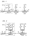
- FIGs. 1 through 3 Several of the many distinct possibilities for producing the desired phase modulation using N RF frequencies are illustrated in FIGs. 1 through 3.
- FIG. 1 for example, each of N tones is applied to a separate phase modulator associated with the particular tone.
- FIG. 2 N/2 phase modulators are shown integrated on a single chip and each modulator is driven with an associated pair of separate frequency drive signals.
- all of the tones are combined electrically into a composite signal which is then applied to a single phase modulator. All of these embodiments are substantially equivalent given the linearity of the operations.
- Each configuration can provide the same functionality as any other. Perhaps the most practical in many circumstances is the last configuration shown in FIG. 3 because of its economic use of elements. While it employs the most elements, the embodiment in FIG. 1 admits to the simplest presentation for purposes of understanding the principles of operation of the present invention.
- FIG. 1 shows a multi-wavelength source for suppressing SBS.
- the embodiment in FIG. 1 includes optical source 11 optically coupled to a serial arrangement of N phase modulator sections 12.
- Each phase modulator section is substantially identical to the others except, of course, for the frequency of the tone and the gain of the adjustable amplifier which controls the amplitude of the drive signal applied to the phase modulator.
- Exemplary phase modulator section 12-1 includes tone generator 121, adjustable amplifier 122, and optical phase modulator 123. These elements are electrically connected within the phase modulator section. Tone generator 121 emits a signal having a particular amplitude at a prescribed frequency. For section 12-1, the tone generator operates at frequency f 1 . Adjustable amplifier 122 is controlled to amplify or attenuate the amplitude of the signal from the tone generator so that the signal has the desired amplitude for the phase modulator drive signal. The output signal from the amplifier is a frequency drive signal.
- the particular phase modulation index of approximately 0,9 ⁇ radians (peak-to-peak) as described above produces an output signal 13 from the associated modulator section having an optical spectrum with first upper and lower optical sidebands, each sideband having an optical power equal to the power remaining in the optical carrier.
- This spectrum is illustrated in FIG. 4 where the optical carrier frequency is shown at ⁇ c , the first order sidebands are shown at ⁇ 1, and the second and higher order sidebands are shown at ⁇ 2, etc.
- the optical spectrum produced by this modulation technique and apparatus has its total optical power substantially evenly distributed among three optical frequencies as shown in FIG. 5.
- the frequency spacing between separate spectral components is determined by the electrical drive frequency.
- the three optical frequency components in this spectrum are ⁇ c , and ⁇ c ⁇ f 1 .
- the first frequency, f 1 is the largest in the set
- the second, f 2 is the second largest and has an illustrative value of one-third of f 1 , i.e. f 2 ⁇ f 1 /3.
- the output of the first phase modulator section 12-1 acts as the optical source for the second phase modulator section 12-2.
- the resulting optical spectrum appears for output optical signal 14 includes nine different spectral components.
- the output spectrum appears as if each of the three optical frequencies in the output of the first modulator section has been phase modulated, as before, to produce their own upper and lower sidebands.
- the distribution of power among all the optical tones is equal because of the selection of the frequency and amplitudes of the different drive signals.
- the output of the second phase modulator has a spectrum consisting of nine equally spaced frequencies centered on the original optical carrier (i.e. input to the first phase modulator) with uniform distribution of the optical power.
- each drive signal occurring at one-third (1/3) the frequency of the lowest frequency drive signal in the previous set of frequency drive signals.
- the optical power will be distributed equally among 3 N optical frequencies.
- the optical power is spread over an optical bandwidth of approximately 3 N times the smallest drive frequency, and the SBS threshold will be increased by the same factor, that is, 3 N .
- the lowest drive frequency should be selected to be 2-3 times larger than the SBS bandwidth to attain the greatest increase in threshold.
- the linear electrooptic effect or Pockels effect which is present in materials such as lithium niobate and compound III-V semiconductors, displays this behavior, namely, producing an optical phase shift as a substantially linear function of the applied electrical signal.
- phase-voltage relation is quadratic, such as in the Kerr effect.
- phase modulator section 22-1 is an exemplary section.
- Phase modulator section 22-1 includes a pair of tone generators 121 and 221 at frequencies f 1 and f 2 , respectively, associated adjustably controllable amplifiers 122 and 222, signal combiner 225 and phase modulator 123.
- This embodiment reduces, by approximately a factor of two, the number of phase modulators required for the multi-wavelength source.
- the signal combiner operates to combine the electrical signals, the two frequency drive signals, output from both connected amplifiers.
- N tone generators 121, 221, and 321 are coupled to associated adjustably controllable amplifiers 122, 222, and 322.
- the amplifier outputs are connected to signal combiner 325 which combines the supplied frequency drive signals for application to phase modulator 123.
- This embodiment provides a considerable decrease in component count (fewer combiners and phase modulators) and is therefore a desirable candidate for integration on a single integrated circuit chip.
- the optical source 11 is a laser
- the source could be realized as a light emitting diode or other light emitting apparatus. Since methods and apparatus for efficiently generating, manipulating, combining, and controllably amplifying electrical signals are well known, details of such methods and apparatus will not be discussed herein.
- Phase modulators such as Mach-Zehnder interferometer waveguide modulators employing dual drives are well known to persons skilled in the art for performing optical phase modulation.
- a second consideration related to the choice of the frequency multiplier is whether the higher-order sidebands fall within the SBS bandwidth of other sidebands. This can occur because SBS interaction does not distinguish tones separated by less than the SBS bandwidth.
- a desired offset of the optical frequencies of the higher-order tones may be accomplished by also choosing a multiplier greater than 3.
- arbitrarily large multiplication factors would result in very inefficient use of the available optical bandwidth and could cause dispersion or crosstalk penalties depending upon the application. For this reason, multiplication factors in the range of 3.1 to 3.5 appear attractive.
- the optical power distribution for a frequency multiplier of 3.5 which has been used experimentally with excellent results, is shown in FIG. 6. While the use of a constant frequency multiplier to specify the frequency hierarchy is conceptually attractive, another scheme is to chose the frequency spacing based on multipliers near 3, but each multiple slightly different from one another.
- phase modulator sections can be interconnected and in turn connected to the source by fiber, dielectric or semiconductor waveguides, or even by free space optics, all of which are well known to persons skilled in the art.
Landscapes
- Physics & Mathematics (AREA)
- Engineering & Computer Science (AREA)
- Electromagnetism (AREA)
- Signal Processing (AREA)
- Computer Networks & Wireless Communication (AREA)
- Nonlinear Science (AREA)
- Crystallography & Structural Chemistry (AREA)
- Optics & Photonics (AREA)
- General Physics & Mathematics (AREA)
- Chemical & Material Sciences (AREA)
- Ceramic Engineering (AREA)
- Optical Communication System (AREA)
- Optical Modulation, Optical Deflection, Nonlinear Optics, Optical Demodulation, Optical Logic Elements (AREA)
Applications Claiming Priority (2)
| Application Number | Priority Date | Filing Date | Title |
|---|---|---|---|
| US08/396,822 US5566381A (en) | 1995-03-02 | 1995-03-02 | Multifrequency lightwave source using phase modulation for suppressing stimulated brillouin scattering in optical fibers |
| US396822 | 1995-03-02 |
Publications (2)
| Publication Number | Publication Date |
|---|---|
| EP0730190A2 true EP0730190A2 (de) | 1996-09-04 |
| EP0730190A3 EP0730190A3 (de) | 1999-06-23 |
Family
ID=23568754
Family Applications (1)
| Application Number | Title | Priority Date | Filing Date |
|---|---|---|---|
| EP96301145A Withdrawn EP0730190A3 (de) | 1995-03-02 | 1996-02-21 | Phasenmodulierte Quelle für Mehrfrequenz-Lichtwellen zur Unterdrückung stimulierter Brillouin-Streuung in optischen Fasern |
Country Status (5)
| Country | Link |
|---|---|
| US (1) | US5566381A (de) |
| EP (1) | EP0730190A3 (de) |
| JP (1) | JPH08313852A (de) |
| KR (1) | KR960033233A (de) |
| AU (1) | AU4579596A (de) |
Cited By (8)
| Publication number | Priority date | Publication date | Assignee | Title |
|---|---|---|---|---|
| EP0932947A4 (de) * | 1996-10-23 | 2000-01-19 | Scientific Atlanta | Unterdrückung der stimulierten brillouin-streuung in einem optischen übertragungssystem |
| GB2359684A (en) * | 1999-10-14 | 2001-08-29 | Siemens Ag | Reduction of stimulated Brillouin backscattering (SBS) in optical transmission systems |
| US7349637B1 (en) | 2003-02-11 | 2008-03-25 | Optium Corporation | Optical transmitter with SBS suppression |
| WO2010034753A1 (fr) * | 2008-09-26 | 2010-04-01 | Commissariat A L'energie Atomique | Methode d'etalement spectral d'un signal a bande etroite |
| GB2468716A (en) * | 2009-03-20 | 2010-09-22 | Univ Dublin City | An optical wavelength comb generator device |
| EP2702738A4 (de) * | 2011-04-26 | 2014-10-08 | Zte Corp | Verfahren und vorrichtung zur erzeugung kohärenter und frequenzgeregelter optischer unterträger |
| WO2024180487A1 (en) * | 2023-02-28 | 2024-09-06 | LEOS S.r.l. | Apparatus and method for protecting an optical amplifier receiving as input a radiation having a plurality of components at different frequence, in particular if the generation of such components is interupted |
| WO2024188900A1 (en) | 2023-03-10 | 2024-09-19 | Leonardo UK Ltd | An optical amplifier system |
Families Citing this family (40)
| Publication number | Priority date | Publication date | Assignee | Title |
|---|---|---|---|---|
| EP0606170A3 (en) * | 1993-01-07 | 1996-11-20 | Nec Corp | Optical transmission system and optical network terminals used therein. |
| JPH10163974A (ja) * | 1996-11-25 | 1998-06-19 | Fujitsu Ltd | 光送信機及び光通信システム |
| DE19710033C1 (de) * | 1997-03-12 | 1998-04-23 | Univ Dresden Tech | Verfahren zur Umsetzung der Signalmodulation der Kanäle eines optischen Multiplex-Systems auf Subcarrierfrequenzen |
| US5991061A (en) * | 1997-10-20 | 1999-11-23 | Lucent Technologies Inc. | Laser transmitter for reduced SBS |
| US6556327B1 (en) * | 1997-11-06 | 2003-04-29 | Matsushita Electric Industrial Co., Ltd. | Signal converter, optical transmitter and optical fiber transmission system |
| US6282003B1 (en) * | 1998-02-02 | 2001-08-28 | Uniphase Corporation | Method and apparatus for optimizing SBS performance in an optical communication system using at least two phase modulation tones |
| US6252693B1 (en) * | 1999-05-20 | 2001-06-26 | Ortel Corporation | Apparatus and method for reducing impairments from nonlinear fiber effects in 1550 nanometer external modulation links |
| US6606178B1 (en) | 1999-09-23 | 2003-08-12 | Corning Incorporated | Method and system to reduce FWM penalty in NRZ WDM systems |
| US6331908B1 (en) | 1999-11-22 | 2001-12-18 | Lucent Technologies Inc. | Optical system for reduced SBS |
| US6535315B1 (en) | 2000-01-21 | 2003-03-18 | New Elite Technologies, Inc. | Optical fiber transmitter for simultaneously suppressing stimulated brillouin scattering and self/external-phase modulation-induced nolinear distortions in a long-distance broadband distribution system |
| US6583901B1 (en) * | 2000-02-23 | 2003-06-24 | Henry Hung | Optical communications system with dynamic channel allocation |
| US6388800B1 (en) | 2000-06-30 | 2002-05-14 | Lucent Technologies Inc. | Raman amplifier with gain enhancement from optical filtering |
| US6831774B2 (en) * | 2000-07-07 | 2004-12-14 | Nippon Telegraph And Telephone Corporation | Multi-wavelength generating method and apparatus based on flattening of optical spectrum |
| US6813448B1 (en) | 2000-07-28 | 2004-11-02 | Adc Telecommunications, Inc. | Suppression of stimulated brillouin scattering in optical transmissions |
| DE10039951C2 (de) * | 2000-08-16 | 2002-10-10 | Siemens Ag | Verfahren und Anordnung zur Kompensation von Kreuzphasenmodulation |
| US6898351B2 (en) | 2000-11-07 | 2005-05-24 | Photon-X, Llc | Optical fiber transmission systems with suppressed light scattering |
| US7127168B2 (en) * | 2001-06-13 | 2006-10-24 | Nippon Telegraph And Telephone Corporation | Multi-wavelength optical modulation circuit and wavelength-division multiplexed optical signal transmitter |
| CN1330119C (zh) * | 2001-11-11 | 2007-08-01 | 华为技术有限公司 | 一种用于高速传输系统的光信号调节方法及光传输系统 |
| GB2383424B (en) * | 2001-11-30 | 2004-12-22 | Marconi Optical Components Ltd | Photonic integrated device |
| US6756772B2 (en) * | 2002-07-08 | 2004-06-29 | Cogency Semiconductor Inc. | Dual-output direct current voltage converter |
| US6798563B2 (en) * | 2002-07-08 | 2004-09-28 | Nortel Networks Limited | Method and device for reducing pump noise transfer in raman amplification |
| US6661815B1 (en) * | 2002-12-31 | 2003-12-09 | Intel Corporation | Servo technique for concurrent wavelength locking and stimulated brillouin scattering suppression |
| US7230712B2 (en) * | 2003-11-03 | 2007-06-12 | Battelle Memorial Institute | Reduction of residual amplitude modulation in frequency-modulated signals |
| US7580630B2 (en) * | 2004-06-07 | 2009-08-25 | Nortel Networks Limited | Spectral shaping for optical OFDM transmission |
| JP2006293247A (ja) * | 2005-03-15 | 2006-10-26 | Optical Comb Institute Inc | 光周波数コム発生方法及び光周波数コム発生装置 |
| US20070140704A1 (en) * | 2005-12-20 | 2007-06-21 | Mauro John C | Optical transmitter with enhanced SBS threshold power capability |
| US7742223B2 (en) | 2006-03-23 | 2010-06-22 | Xtera Communications, Inc. | System and method for implementing a boosterless optical communication system |
| US8494378B2 (en) * | 2006-07-11 | 2013-07-23 | Japan Science And Technology Agency | Synchronous optical signal generating device and synchronous optical signal generating method |
| JP4827672B2 (ja) * | 2006-09-21 | 2011-11-30 | 富士通株式会社 | Wdm光伝送システムおよびwdm光伝送方法 |
| US7782911B2 (en) * | 2007-02-21 | 2010-08-24 | Deep Photonics Corporation | Method and apparatus for increasing fiber laser output power |
| CN101141200B (zh) * | 2007-10-15 | 2010-08-04 | 哈尔滨工业大学 | 基于多频相位调制的多波长源产生装置 |
| WO2010057290A1 (en) * | 2008-11-21 | 2010-05-27 | Institut National Optique | Spectrally tailored pulsed fiber laser oscillator |
| US8908266B2 (en) | 2011-12-01 | 2014-12-09 | Halliburton Energy Services, Inc. | Source spectrum control of nonlinearities in optical waveguides |
| CN102854697B (zh) * | 2012-09-26 | 2015-03-25 | 哈尔滨工业大学 | 抑制横向非线性效应提高大口径光学元器件安全性的方法及装置 |
| US9310185B2 (en) * | 2013-06-12 | 2016-04-12 | Medlumics, S.L. | Electro-optical silicon-based phase modulator with null residual amplitude modulation |
| CN104734783B (zh) * | 2015-04-13 | 2017-08-15 | 天津理工大学 | 一种任意波形光脉冲发生器 |
| US11784719B1 (en) * | 2020-04-01 | 2023-10-10 | Cable Television Laboratories, Inc. | Systems and methods for tuning a power characteristic of an optical frequency comb |
| CN113225133B (zh) * | 2021-05-06 | 2022-12-16 | 武汉锐科光纤激光技术股份有限公司 | 窄线宽种子源及激光光谱展宽的方法 |
| CN113852424B (zh) * | 2021-09-23 | 2023-02-28 | 杭州爱鸥光学科技有限公司 | 种子源光谱展宽方法、装置及高功率连续光纤激光器系统 |
| CN118466054A (zh) * | 2024-05-27 | 2024-08-09 | 中国科学院上海光学精密机械研究所 | 一种基于薄膜铌酸锂调制器的集成化多级调制装置 |
Family Cites Families (6)
| Publication number | Priority date | Publication date | Assignee | Title |
|---|---|---|---|---|
| US5295209A (en) * | 1991-03-12 | 1994-03-15 | General Instrument Corporation | Spontaneous emission source having high spectral density at a desired wavelength |
| US5166821A (en) * | 1991-03-12 | 1992-11-24 | General Instrument Corporation | Reduction of non-linear effects in optical fiber communication systems and method of using same |
| JP3223562B2 (ja) * | 1992-04-07 | 2001-10-29 | 株式会社日立製作所 | 光送信装置、光伝送装置および光変調器 |
| US5303079A (en) * | 1992-04-09 | 1994-04-12 | At&T Bell Laboratories | Tunable chirp, lightwave modulator for dispersion compensation |
| JPH06209293A (ja) * | 1992-07-31 | 1994-07-26 | American Teleph & Telegr Co <Att> | 光伝送システムにおける変調装置 |
| US5329396A (en) * | 1992-10-28 | 1994-07-12 | At&T Bell Laboratories | Reduction of stimulated brillouin scattering in a fiber optic transmission system |
-
1995
- 1995-03-02 US US08/396,822 patent/US5566381A/en not_active Expired - Lifetime
-
1996
- 1996-02-21 EP EP96301145A patent/EP0730190A3/de not_active Withdrawn
- 1996-02-27 JP JP8039246A patent/JPH08313852A/ja active Pending
- 1996-02-28 AU AU45795/96A patent/AU4579596A/en not_active Abandoned
- 1996-02-29 KR KR1019960005208A patent/KR960033233A/ko not_active Withdrawn
Cited By (10)
| Publication number | Priority date | Publication date | Assignee | Title |
|---|---|---|---|---|
| EP0932947A4 (de) * | 1996-10-23 | 2000-01-19 | Scientific Atlanta | Unterdrückung der stimulierten brillouin-streuung in einem optischen übertragungssystem |
| GB2359684A (en) * | 1999-10-14 | 2001-08-29 | Siemens Ag | Reduction of stimulated Brillouin backscattering (SBS) in optical transmission systems |
| US7349637B1 (en) | 2003-02-11 | 2008-03-25 | Optium Corporation | Optical transmitter with SBS suppression |
| WO2010034753A1 (fr) * | 2008-09-26 | 2010-04-01 | Commissariat A L'energie Atomique | Methode d'etalement spectral d'un signal a bande etroite |
| FR2936671A1 (fr) * | 2008-09-26 | 2010-04-02 | Commissariat Energie Atomique | Methode d'etalement spectral d'un signal a bande etroite |
| US8483321B2 (en) | 2008-09-26 | 2013-07-09 | Commissariat à l'énergie atomique et aux énergies alternatives | Method for spreading the spectrum of a narrowband signal |
| GB2468716A (en) * | 2009-03-20 | 2010-09-22 | Univ Dublin City | An optical wavelength comb generator device |
| EP2702738A4 (de) * | 2011-04-26 | 2014-10-08 | Zte Corp | Verfahren und vorrichtung zur erzeugung kohärenter und frequenzgeregelter optischer unterträger |
| WO2024180487A1 (en) * | 2023-02-28 | 2024-09-06 | LEOS S.r.l. | Apparatus and method for protecting an optical amplifier receiving as input a radiation having a plurality of components at different frequence, in particular if the generation of such components is interupted |
| WO2024188900A1 (en) | 2023-03-10 | 2024-09-19 | Leonardo UK Ltd | An optical amplifier system |
Also Published As
| Publication number | Publication date |
|---|---|
| EP0730190A3 (de) | 1999-06-23 |
| JPH08313852A (ja) | 1996-11-29 |
| US5566381A (en) | 1996-10-15 |
| KR960033233A (ko) | 1996-10-22 |
| AU4579596A (en) | 1996-09-12 |
Similar Documents
| Publication | Publication Date | Title |
|---|---|---|
| US5566381A (en) | Multifrequency lightwave source using phase modulation for suppressing stimulated brillouin scattering in optical fibers | |
| US6342961B1 (en) | Method and apparatus for improving spectral efficiency in wavelength division multiplexed transmission systems | |
| Zeng et al. | Investigation of phase-modulator-based all-optical bandpass microwave filter | |
| US7146110B2 (en) | Optical transmitter with SBS suppression | |
| Ho et al. | Narrow-linewidth idler generation in fiber four-wave mixing and parametric amplification by dithering two pumps in opposition of phase | |
| US6847758B1 (en) | Method, optical device, and system for optical fiber transmission | |
| US5828477A (en) | Multi-tone phase modulation for light wave communication system | |
| EP0570984A1 (de) | Unterdrücken von Rauschen und Verzerrungen in einem Lichtwellenleitersystem | |
| US20020191904A1 (en) | Multi-wavelength optical modulation circuit and wavelength-division multiplexed optical signal transmitter | |
| US5063559A (en) | Optimized wavelength-division-multiplexed lightwave communication system | |
| US7127182B2 (en) | Efficient optical transmission system | |
| JP3516032B2 (ja) | 光周波数変換装置 | |
| WO1996037042A1 (en) | Method and apparatus for transmitting signals in an optical fibre | |
| US20060251425A1 (en) | Suppression of fiber-induced noise caused by narrow linewidth lasers | |
| US5548603A (en) | Method for the generation of ultra-short optical pulses | |
| US20020141027A1 (en) | Variable pulse width optical pulse generation with superposed multiple frequency drive | |
| KR100617709B1 (ko) | 주파수 변조 방식의 광송신 장치 및 방법 | |
| Solgaard et al. | Millimeter wave, multigigahertz optical modulation by feedforward phase noise compensation of a beat note generated by photomixing of two laser diodes | |
| US8537452B2 (en) | System and method for generating optical radiation of controllable spectral content | |
| EP1168042A2 (de) | Optischer Frequenzwandler mit reziproker Modulation | |
| JP3343241B2 (ja) | 逓倍光変調装置 | |
| US5432631A (en) | Dual-wavelength source of high-repetition rate, transform-limited optical pulses | |
| CN114389698B (zh) | 一种微波信号的产生装置及方法 | |
| KR20210129301A (ko) | 다중 채널 광 신호 생성 장치 | |
| US20020196503A1 (en) | Method and system for dispersion control of electromagnetic signals in communication networks |
Legal Events
| Date | Code | Title | Description |
|---|---|---|---|
| PUAI | Public reference made under article 153(3) epc to a published international application that has entered the european phase |
Free format text: ORIGINAL CODE: 0009012 |
|
| AK | Designated contracting states |
Kind code of ref document: A2 Designated state(s): ES GB IT SE |
|
| PUAL | Search report despatched |
Free format text: ORIGINAL CODE: 0009013 |
|
| AK | Designated contracting states |
Kind code of ref document: A3 Designated state(s): ES GB IT SE |
|
| STAA | Information on the status of an ep patent application or granted ep patent |
Free format text: STATUS: THE APPLICATION IS DEEMED TO BE WITHDRAWN |
|
| 18D | Application deemed to be withdrawn |
Effective date: 19990302 |