EP0730982A2 - Instrument d'écriture et méthode de fabrication - Google Patents
Instrument d'écriture et méthode de fabrication Download PDFInfo
- Publication number
- EP0730982A2 EP0730982A2 EP96102944A EP96102944A EP0730982A2 EP 0730982 A2 EP0730982 A2 EP 0730982A2 EP 96102944 A EP96102944 A EP 96102944A EP 96102944 A EP96102944 A EP 96102944A EP 0730982 A2 EP0730982 A2 EP 0730982A2
- Authority
- EP
- European Patent Office
- Prior art keywords
- main shaft
- holder unit
- helicoid
- ink holder
- ink
- Prior art date
- Legal status (The legal status is an assumption and is not a legal conclusion. Google has not performed a legal analysis and makes no representation as to the accuracy of the status listed.)
- Granted
Links
- 238000004519 manufacturing process Methods 0.000 title claims description 13
- 230000008878 coupling Effects 0.000 claims abstract description 63
- 238000010168 coupling process Methods 0.000 claims abstract description 63
- 238000005859 coupling reaction Methods 0.000 claims abstract description 63
- 238000003780 insertion Methods 0.000 claims abstract description 12
- 230000037431 insertion Effects 0.000 claims abstract description 12
- 230000015572 biosynthetic process Effects 0.000 claims abstract description 3
- 239000000463 material Substances 0.000 claims description 6
- 238000000034 method Methods 0.000 claims description 5
- 239000013013 elastic material Substances 0.000 abstract description 6
- 238000000605 extraction Methods 0.000 abstract description 4
- 239000000284 extract Substances 0.000 description 4
- 208000004350 Strabismus Diseases 0.000 description 3
- 239000000853 adhesive Substances 0.000 description 3
- 239000004743 Polypropylene Substances 0.000 description 2
- 239000004033 plastic Substances 0.000 description 2
- 229920003023 plastic Polymers 0.000 description 2
- 229920001225 polyester resin Polymers 0.000 description 2
- 239000004645 polyester resin Substances 0.000 description 2
- 229920013716 polyethylene resin Polymers 0.000 description 2
- -1 polypropylene Polymers 0.000 description 2
- 229920001155 polypropylene Polymers 0.000 description 2
- 230000002411 adverse Effects 0.000 description 1
- 230000003292 diminished effect Effects 0.000 description 1
- 230000000694 effects Effects 0.000 description 1
- 238000001746 injection moulding Methods 0.000 description 1
- 239000000203 mixture Substances 0.000 description 1
- 238000010422 painting Methods 0.000 description 1
- 229920005989 resin Polymers 0.000 description 1
- 239000011347 resin Substances 0.000 description 1
- 231100000241 scar Toxicity 0.000 description 1
- 238000009751 slip forming Methods 0.000 description 1
Images


Classifications
-
- B—PERFORMING OPERATIONS; TRANSPORTING
- B43—WRITING OR DRAWING IMPLEMENTS; BUREAU ACCESSORIES
- B43K—IMPLEMENTS FOR WRITING OR DRAWING
- B43K24/00—Mechanisms for selecting, projecting, retracting or locking writing units
-
- B—PERFORMING OPERATIONS; TRANSPORTING
- B43—WRITING OR DRAWING IMPLEMENTS; BUREAU ACCESSORIES
- B43K—IMPLEMENTS FOR WRITING OR DRAWING
- B43K15/00—Assembling, finishing, or repairing pens
-
- F—MECHANICAL ENGINEERING; LIGHTING; HEATING; WEAPONS; BLASTING
- F16—ENGINEERING ELEMENTS AND UNITS; GENERAL MEASURES FOR PRODUCING AND MAINTAINING EFFECTIVE FUNCTIONING OF MACHINES OR INSTALLATIONS; THERMAL INSULATION IN GENERAL
- F16B—DEVICES FOR FASTENING OR SECURING CONSTRUCTIONAL ELEMENTS OR MACHINE PARTS TOGETHER, e.g. NAILS, BOLTS, CIRCLIPS, CLAMPS, CLIPS OR WEDGES; JOINTS OR JOINTING
- F16B37/00—Nuts or like thread-engaging members
- F16B37/005—Nuts or like thread-engaging members into which threads are cut during screwing
Definitions
- the present invention relates to a writing utensil such as a ball pen, more particularly, to a writing utensil capable of easily inserting and extracting ink holder unit.
- the invention can also be applied to coupling structure of male and female members to be inserted into and extracted from a female member such as a main shaft for storing a male member such as a tip stopper for holding tip portion of the ink holding unit.
- a conventional writing utensil such as a ball pen having an ink holder unit being stored in a cylindrical main shaft and tip portion of the ink holder unit projecting from the main shaft being fixed by a tip stopper integrated with the main shaft.
- a external screw(thread) is formed in the main shaft against a internal screw(thread) formed in the tip stopper.
- the main shaft is integrated with the tip stopper by way of coupling the external screw of the main shaft and the internal screw of the tip stopper.
- Such a conventional ball pen having the above structure can easily extract the ink holder unit therefrom, and thus, only the ink holder unit can be drawn out of the main shaft to replace it with the new one whenever the stored ink is run out. Since the above-cited ball pen can repeatedly use the main shaft, it is quite economical and preferred for business use.
- the reason for coupling the external and internal screws and integrating the main shaft internally forming the internal screw and the tip stopper internally forming the external screw is to prevent the ink holder unit from slipping out of the main shaft. Accordingly, there is such a conventional ball pen which prevents the ink holder unit from slipping out of the main shaft by way of fixing the main shaft and the tip stopper with adhesive agent instead of coupling screws. According to this structure, since the main shaft and the tip stopper are merely coated with adhesive agent for insertion, this structure is suited for mass production.
- the ball pen Since screwing work is not needed on the way of assembling the above-cited ball pen and the ink holder unit is replaceable, the ball pen generally satisfies the above demand.
- the above-cited ball pen allowing forced insertion of the tip stopper without forming a external screw into the main shaft without forming a internal screw contains substantial coupling force between the tip stopper portion and the main shaft, and yet, the tip stopper portion is tapered to incur grasping inconvenience, and thus, extraction of the ink holder unit from the main shaft cannot be done very easily.
- the object of the invention is to provide a novel writing utensil allowing easy extraction of the ink holder unit therefrom and also provide a novel method of manufacturing it as well as easy insertion of the ink holder unit into the main shaft and fixation therein .
- the inventive art uses an ink cylinder internally storing ink and an ink holder unit integrating a tip stopper with a writing chip.
- Either the ink holder unit or the main shaft is provided with helicoid form.
- assembly of the writing utensil can be done by forcible insertion of the integrated ink holder unit into the main shaft, and thus, the inventive writing utensil can be assembled very easily and suited for mass production.
- the novel writing utensil according to the invention disclose only ink holder unit is rotated. Then, since either the ink holder unit or the main shaft is provided with helicoid form, the used ink holder unit proceeds itself in the axial direction along helicoid form and leave the main shaft.
- helicoid form is provided for either the ink holder unit or the main shaft. It is also desirable to embody such a structure to form a rib extending itself in the axial direction on the other part of either the ink holder unit or the main shaft to cause the helicoid form to be engaged with the rib.
- the rib since the rib is formed in such a position coming into contact with the helicoid form, tip portion of the rib comes into contact with the helicoid form to enable both to be brought into contact with each other via substantial force of pressure per unit area. In consequence, the helicoid form is engaged with the rib to exert greater resisting force against slip-off of the ink holder unit. In addition, since engagement of the helicoid form with the rib is promoted furthermore, it facilitates smoother axial-directional movement of the ink holder unit when being rotated.
- the coupling structure used for the invention is also available for fixing tail stopper of a writing utensil or bonding of materials other than writing utensils.
- helicoid is formed on external circumference of engaging portion of a male member or internal circumference of a female member to enable the helicoid to be engaged with the other component.
- the invention can be applied to such a ball pen shown in Fig. 1 for example.
- the ball pen shown in Fig. 1 comprises a cylindrical main shaft 20 and an ink holder unit 1 inserted therein.
- the ink holder unit 1 according to the invention comprises an ink cylinder 3, a tip stopper 10, and a ball pen chip 2.
- the ink cylinder 3 is a tube made from a plastic such as polypropylene or polyethylene resin for example in which conventional aqueous or oily ink is stored (not illustrated).
- the tip stopper 10 be made from polypropylene resin, or polyethylene resin, or polyester resin, or the like. More desirably, the tip stopper 10 is formed via injection molding of polyester resin containing high hardness. Tip portion of the tip stopper 10 is of cone shape, whereas the rear portion is of cylindrical form. A helicoid screw(thread) 11 is formed in the middle portion of the tip stopper 10. A through-hole (not shown) for feeding ink is provided in the center of the tip stopper 10.
- the ball pen chip 2 comprises a metallic ball holder and a rotative ball inserted therein.
- the ink holder unit 1 comprises the tip stopper 10 which is inserted in the tip portion of the ink cylinder 3 and the ball pen chip 2 secured to the tip portion of the tip stopper 10 by way of integrating three components altogether.
- the tip stopper 10 functions as a male member
- the main shaft 20 functions as a female member.
- the tip stopper 10 and the main shaft 20 can also be structured as per the drawings exemplified by way of the second through ninth embodiments.
- a helicoid screw 11 is formed on external circumference of the tip stopper 10 functioning as the male member.
- no screw is formed on the main shaft 20 functioning as the female member, where the main shaft 20 is made from elastic material so that the helicoid screw 11 can bite thereinto. It is thus desired that the main shaft 20 be made from such material having hardness lower than that is used for the tip stopper 10.
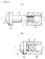
- Fig. 2 exemplifies the same embodiment as that is shown in Fig. 1, in which fundamental components are shown as model for easier explanation of functions.
- the second embodiment of the invention forms a screw(thread) 21 around internal circumference of an edge of the main shaft 20, whereas no screw is formed on the tip stopper 10, where the tip stopper 10 is made from elastic material so that the screw 21 can bite thereinto.
- Elasticity of elastic material used for embodying the invention does not always require significant deformed capacity, but it is quite enough to cause the elastic material to slightly recess at the moment at which the elastic material is tightly pressed by the tip portions of the screws 11 and 21. Accordingly, when applying the invention to a ball pen, main shaft of such a conventionally known ball pen can be made available.
- Coupling portion 12 of the tip stopper 10 may be in parallel. However, it is also practicable for the invention to slightly contract diameter of the edge of the coupling portion 12 to provide tapered form so that the coupling portion 12 can easily be inserted into the main shaft 20.
- the coupling portion 12 of the tip stopper 10 is coupled with the interior of the main shaft 20 in the state in which either the screw 11 of the tip stopper 10 or the screw 21 of the main shaft 20 bites into inner circumferential surface of the main shaft 20 or outer circumferential surface of the tip stopper 10.
- Fig. 2(b) and Fig. 4(b) respectively illustrate the state in which the screws 11 and 21 have fully bitten into inner circumferential surface of the main shaft 20 or outer circumferential surface of the tip stopper 10. It is however allowable to generate such a condition in which only the tip end of the screws 11 and 21 remains slightly biting into corresponding circumferential surface.
- helicoid space is formed between the ink holder unit 1 and inner surface of the main shaft 20 by way of interlinking inner and outer portions of the main shaft 20, and thus, helicoid space functions as air-vent hole.
- the ink holder unit 1 is prevented from easily slipping off from the main shaft 20. And yet, since the ink holder unit 1 can be engaged with the interior of the main shaft 20 merely by forcibly inserting the tip stopper 10, it is possible for the inventive art to quickly assemble a large amount of ball pens.
- assembly of ball pens according to the first embodiment of the invention is executed by way of the following steps.
- the ink holder unit 1 and the main shaft 20 shown in Fig. 1 are previously formed.
- the tip stopper 10 and the ball pen chip 2 are integrated at the tip portion of the ink cylinder 3 followed by a step to manufacture the ink holder unit 1 including the tip stopper 10 having screw portion 11 formed on the middle part thereof.
- the cylindrical main shaft 20 is produced.
- the ink holder unit 1 is forcibly inserted into the hollow main shaft 20.
- the ink holder unit 1 is straightforwardly inserted into the main shaft 20 without causing the ink holder unit 1 and the main shaft 20 to rotate themselves relative to each other.
- the screw 11 formed on the tip stopper 10 of the ink holder unit 1 are inserted in the main shaft 20 to cause the ink holder unit 1 to be secured to the main shaft 20.
- Steps for assembling the ball pen according to the second embodiment of the invention are described below.
- the ink holder unit 1 and the main shaft 20 are previously formed.
- the screw 21 is solely formed at the inner edge portion of the main shaft 20, whereas no screw is formed in the tip stopper 10.
- the ink holder unit 1 is forcibly inserted into the hollow main shaft 20.
- the ink holder unit 1 When replacing the empty ink holder unit 1 after fully running out of ink, user extracts the ink holder unit 1 by rotating the tip stopper portion 10 of the ink holder unit 1 in the manner of loosening the screw. In this condition, the screw 11 or 21 provided for the tip stopper 10 or the main shaft 20 still bites the other component member thereby causing the other component member to form provisional screw form. Accordingly, when user rotates the tip stopper 10, the ink holder unit 1 proceeds in conjunction with the tip stopper 10 along the screw 11 or 21 before causing the ink holder unit 1 to leave the main shaft 20.
- the tip stopper 10 Since user individually replaces the ink holder unit 1, there is no need to quickly replace the ink holder unit on the massive basis. Furthermore, the tip stopper 10 does not maintain engagement via friction force caused by forcible insertion thereof, but it merely maintains axial-directional engagement via biting of screw, and thus, even if user may incur some inconvenience in grasping the tip stopper 10, he may simply exert weak rotating force by way of loosening the screw so that he can easily extract the tip stopper 10 from the main shaft 20.
- the coupling portion 12 of the tip stopper 10 is engaged with the main shaft 20. Accordingly, user can easily couple the tip stopper 10 with the main shaft 20.
- Replaced ink holder unit 1 causes internal-screw shape trace to remain on inner surface of the main shaft 20, and thus, whenever replacing the empty ink holder unit 1 with the new one, the tip stopper 10 can be coupled with the main shaft 20 merely by rotating the new ink holder unit 1 after inserting it into the main shaft 20.
- the third embodiment forms an air slit 14 continuously running across surface of the coupling portion 12 of the tip stopper 10 and inner surface of an expanded-diameter portion 13.
- This structure is specifically applicable to the case in which the invention is applied to ball pens as the premise.
- interval between the screw 11 of the coupling portion 12 and inner surface of the main shaft 20 rarely becomes fully closed, and instead, since slight clearance is generated in the screw slit, as shown in Fig. 5(b), the interior and exterior of the main shaft 20 can be linked to each other merely by providing either a cutout portion or the air slit 14 only at the edge surface of the tip stopper 10.
- the fourth embodiment provides the tail stopper C with the coupling structure identical to that is used for the ink holder unit 1 by way of forming a cutout portion 15 in the coupling portion 12 of the tail stopper C. Since the ink holder unit 1 is not secured to the tail stopper C, a 12cutout portion 15 can be formed. As a result of provision of the cutout portion 15, diameter of the coupling portion 12 can easily be contracted to facilitate easier insertion of the coupling portion 12 into the main shaft 20. By virtue of provision of a shallow slit 16 linking to the cutout portion 15 in the expanded-diameter portion 13 of the tail stopper 13, both the cutout portion 15 and the shallow slit 16 function as air vent. As shown in Fig.
- screw is formed in either the coupling portion 12 of the tail stopper C or the main shaft 20 so that the screw can bite into inner circumferential surface of the main shaft 20 or outer circumferential surface of the coupling portion 12 of the tail stopper C.
- the fifth embodiment provides inner circumferential surface of the main shaft 20 with a plurality of projected ribs 23 respectively coming into contact with outer circumferential surface of the tip stopper 10.
- the ribs 23 are projecting formed in the longitudinal direction of the main shaft 20 in order that they can slightly bite into outer circumferential surface of the coupling portion 12 of the tip stopper 10.
- the fifth embodiment also forms screw on either the coupling portion 12 of the tip stopper 10 or the main shaft 20.
- screw is continuously formed in the same way as was done for the preceding embodiments.
- screw is formed on the ribs 23, and thus, screws are not continuous.
- the tip stopper 10 comes into contact with the main shaft 20 via the ribs 23. Accordingly, since contactable area between the tip stopper 10 and the main shaft 20 is less than that is generated when both members 10 and 20 are brought into contact on the whole circumferential surfaces, friction resistance is reduced to facilitate easier insertion of the coupling portion 12 of the tip stopper 10 into the main shaft 20.
- the coupling portion 12 of the tip stopper 10 When the coupling portion 12 of the tip stopper 10 is fully inserted into the main shaft 20, the ribs 23 of the main shaft 20 bite into surface of the coupling portion 12 of the tip stopper10, and then, the coupling portion 12 of the tip stopper 10 concentrically receives load from the ribs 23 to cause the tip stopper 10 to be hardly disengageable from the main shaft 20.
- the tip stopper 10 since there is merely negligible area of contact between the coupling portion 12 of the tip stopper 10 and the main shaft 20, when user rotates the tip stopper 10 with negligible force by way of loosening screw, the tip stopper 10 can be extracted from the main shaft 20 very easily.
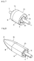
- the sixth and seventh embodiments are also applied to the composition of ball pens, in which the main shaft 20 is formed by way of polygonal cylindrical structure. Concretely, the sixth embodiment uses the main shaft 20 having hexagonal cylindrical form shown in Fig. 8. The seventh embodiment uses the main shaft 20 having triangular cylindrical form. The sixth and seventh embodiments also from screw on the coupling portion 12 of the tip stopper 10 or the main shaft 20.
- main shaft 20 having polygonal outer circumferential surface
- novelty of design can be generated. If inner circumferential surface of the main shaft 20 is of circular form in close contact with outer circumferential surface of the coupling portion 12 of the tip stopper 10, it results in the same structure as that is applied in the first and second embodiments. However, as shown in Fig. 8 and Fig. 9, by provision of the main shaft 20 having hexagonal or triangular inner circumferential surface, the main shaft 20 comes into contact with the coupling portion 12 of the tip stopper 10 via tangent. Accordingly, it results in the diminished friction resistance between the main shaft 20 and the coupling portion 12 of the tip stopper 10 to facilitate easier insertion of the tip stopper 10 into the main shaft 20. When user rotates the tip stopper 10 with negligible force by way of loosening screw, the tip stopper 10 can be extracted from the main shaft 20 very easily.
- the above-described fifth and sixth embodiments respectively form space 4 between inner circumferential surface of the main shaft 20 and outer circumferential surface of the tip stopper 10.
- space 4 can serve as air vent.
- the eighth embodiment exemplifies an example of more complete linkage between the interior and the exterior of the main shaft 20.
- the ball pen of the eighth embodiment uses the ink holder unit 1 having the form substantially identical to that is used for the first embodiment.
- the ink holder unit 1 comprises an ink cylinder 3, a tip stopper 10, and a ball pen chip 2. Front edge portion of the tip stopper 10 is of cone shape, whereas rear edge portion is of cylindrical form. Helicoid M6 screw 11 is formed in the middle portion of the ink holder unit 1.
- the tip stopper 10 of the eighth embodiment differs from the tip stopper 10 prepared for the first embodiment in that cutout portion 18 is formed at the front-end step portion, concretely, on the screw side of the front portion, where the cutout portion 18 extends from surface portion of the tip stopper 10 to the height of screw 11.
- a plurality of ribs 19 are formed on inner surface at the edge portion of the main shaft 20.
- the eighth embodiment provides 5 equiangularly disposed ribs 19.
- Each rib 19 is as low as 0.3mm in height and of arc form.
- the ball pen of the eighth embodiment is assembled via steps identical to the preceding embodiments. Concretely, after forming the ink holder unit 1 and the main shaft 20, the ink holder unit 1 is forcibly inserted into the main shaft 20, and then screw portion 11 of the tip stopper 10 is thrusted into edge portion of the main shaft 20 straightforwardly. As a result, tip end of the screw 11 bites into the ribs 19 to cause the ink holder unit 1 to be engaged with the main shaft 20.
- the eighth embodiment provides a cutout portion 18 in the tip stopper 10, where the cutout portion 18 extends from surface of the tip stopper 10 up to the actual height of the screw 11.
- a plurality of ribs 19 are disposed around contactable edge of the main shaft 20 against screw 11. Space is generated between the main shaft 20 and the tip stopper 10. Furthermore, although the screw 11 bites inner surface of the main shaft 20, there is slight clearance between the bottom of screw slits and inner surface of the main shaft 20.
- the eighth embodiment interlinks the interior and the exterior of the main shaft 20 via the cutout portion 18 extended from surface of the tip stopper 10, and either clearance between the ribs 19, or through the screws 11.
- the ninth embodiment shown in Fig. 11 provides another formation of the ribs of the eighth embodiment.
- the ninth embodiment provides the rib 19 having flat peak portion and five chords against circular arc. It is understood from observation of the form of edge surface of the main shaft 20 according to the ninth embodiment that the flat peak ribs 19 and circular-arc-shaped portions 21 are alternately disposed by way of making up substantially a pentagonal form with rounded corners.
- the screw 11 of the tip stopper 10 bites into a part of the pentagonal portion.
- the interior and the exterior of the main shaft 20 are interlinked via the cutout portion 18 extended from surface of the tip stopper 10, and either clearance between the ribs 19, or the screw 11.
- the coupling structure of the invention is also applicable to the coupling of a tip stopper and a main shaft of a ball pen consisting of discretely prepared tip stopper and ink holder unit as is cited in a first stage of the description of the prior arts.
- the novel coupling structure of the invention is effectively applicable not only to an extensive range of writing utensils, but also to all kinds of products in which male members are engageable with female members.
- male and female members are not merely confined to the tip stopper or the main shaft of a ball pen, but they can also be applied to a cap and tube unit of painting utensil.
- screw is recommended for the above embodiments. It is also permissible to introduce any form other than helicoid screw such as drill form, core structure of an extruding machine, or discontinuous projected line or recessed slit, for example.
- writing utensils can be assembled by way of thrusting ink holder unit into main shaft in the same way as is done by prior arts, and thus, the inventive art is suited for mass production of writing utensils.
- a male member can be thrusted into a female member merely by pushing it, it usefully serves for mass production. And yet, since the male and female members can be engaged with each other via helicoid, the male member cannot easily be disengaged from the corresponding female member, thus resulting in the enhanced reliability on product quality. Furthermore, since the male member is disengageable from the corresponding female member merely by rotating it, extracting work can be done very easily to promote handling convenience.
Landscapes
- Engineering & Computer Science (AREA)
- Mechanical Engineering (AREA)
- General Engineering & Computer Science (AREA)
- Pens And Brushes (AREA)
- Mutual Connection Of Rods And Tubes (AREA)
- Joints That Cut Off Fluids, And Hose Joints (AREA)
Applications Claiming Priority (6)
| Application Number | Priority Date | Filing Date | Title |
|---|---|---|---|
| JP74600/95 | 1995-03-06 | ||
| JP7460095 | 1995-03-06 | ||
| JP7460095 | 1995-03-06 | ||
| JP18408/96 | 1996-01-08 | ||
| JP01840896A JP3505308B2 (ja) | 1995-03-06 | 1996-01-08 | 筆記具、筆記具の製造方法および雄・雌部材の嵌合構造 |
| JP1840896 | 1996-01-08 |
Publications (3)
| Publication Number | Publication Date |
|---|---|
| EP0730982A2 true EP0730982A2 (fr) | 1996-09-11 |
| EP0730982A3 EP0730982A3 (fr) | 1996-10-09 |
| EP0730982B1 EP0730982B1 (fr) | 1999-06-16 |
Family
ID=26355076
Family Applications (1)
| Application Number | Title | Priority Date | Filing Date |
|---|---|---|---|
| EP96102944A Expired - Lifetime EP0730982B1 (fr) | 1995-03-06 | 1996-02-28 | Instrument d'écriture et méthode de fabrication |
Country Status (6)
| Country | Link |
|---|---|
| US (1) | US5938361A (fr) |
| EP (1) | EP0730982B1 (fr) |
| JP (1) | JP3505308B2 (fr) |
| KR (1) | KR100434620B1 (fr) |
| DE (1) | DE69602860T2 (fr) |
| TW (1) | TW330896B (fr) |
Cited By (1)
| Publication number | Priority date | Publication date | Assignee | Title |
|---|---|---|---|---|
| CN104129200A (zh) * | 2014-08-19 | 2014-11-05 | 单仁德 | 一种地书笔 |
Families Citing this family (19)
| Publication number | Priority date | Publication date | Assignee | Title |
|---|---|---|---|---|
| JP4723702B2 (ja) * | 1999-06-04 | 2011-07-13 | シヤチハタ株式会社 | 筆記具及びペン芯ホルダー離脱方法 |
| JP4748897B2 (ja) * | 2001-08-15 | 2011-08-17 | 三菱鉛筆株式会社 | 筆記具 |
| US6769380B1 (en) * | 2002-07-05 | 2004-08-03 | Producciones Generales-Progen S.A. | Modular marker |
| CN2640760Y (zh) * | 2003-01-24 | 2004-09-15 | 刘保伸 | 异轴笔的持握部改良结构 |
| US7461991B2 (en) * | 2005-07-19 | 2008-12-09 | Waterman Sas | Quick release mechanism for access to ink reservoir of writing instrument |
| JP4711405B2 (ja) * | 2005-08-30 | 2011-06-29 | 神 規人 | 漆塗装品製造方法、およびそれ用の研ぎ出し装置 |
| JP4913483B2 (ja) * | 2006-06-23 | 2012-04-11 | ゼブラ株式会社 | 筆記部の接続構造 |
| JP5035976B2 (ja) * | 2007-08-01 | 2012-09-26 | 三菱鉛筆株式会社 | ボールペン |
| CN102555597B (zh) * | 2011-12-29 | 2014-12-24 | 贝发集团股份有限公司 | 一种水笔自动装配线 |
| CN102555433A (zh) | 2011-12-29 | 2012-07-11 | 贝发集团股份有限公司 | 一种用于笔杆热转印的设备 |
| CN102529505B (zh) | 2011-12-29 | 2014-05-07 | 贝发集团股份有限公司 | 一种用于实现颗粒状饰物均匀灌装的振动机 |
| CN102555598B (zh) | 2011-12-29 | 2015-02-04 | 贝发集团股份有限公司 | 一种扁形笔自动装配线 |
| JP6255905B2 (ja) * | 2013-10-31 | 2018-01-10 | ぺんてる株式会社 | 軸筒の連結構造 |
| JP2018126962A (ja) * | 2017-02-10 | 2018-08-16 | モリス コーポレーションMorris Corporation | 出没式筆記具 |
| JP7014395B2 (ja) * | 2017-03-27 | 2022-02-15 | 株式会社NejiLaw | ねじ体の相対回転抑制構造、相対移動抑制構造、相対移動抑制体 |
| WO2018180737A1 (fr) * | 2017-03-27 | 2018-10-04 | 株式会社NejiLaw | Structure de prévention de rotation relative pour vis, structure de prévention de mouvement relatif et corps de prévention de mouvement relatif |
| JP7199785B2 (ja) * | 2018-02-28 | 2023-01-06 | 株式会社吉野工業所 | 吐出容器 |
| JP7214323B2 (ja) * | 2019-03-29 | 2023-01-30 | 株式会社吉野工業所 | 吐出容器 |
| JP7242405B2 (ja) * | 2019-04-25 | 2023-03-20 | 株式会社吉野工業所 | 吐出容器 |
Family Cites Families (15)
| Publication number | Priority date | Publication date | Assignee | Title |
|---|---|---|---|---|
| FR970015A (fr) * | 1948-08-05 | 1950-12-28 | Stylo à bille à niveau d'encre visible et cartouches d'encre interchangeables | |
| DE832720C (de) * | 1950-10-05 | 1952-02-28 | Kaweco Badische Fuellfederfabr | Kugelschreiber mit Tintenfuellung |
| GB815049A (en) * | 1956-12-13 | 1959-06-17 | Gen Motors Corp | Improvements in or relating to self-threading fastener devices, particularly threadable sockets of such devices |
| US3255795A (en) * | 1964-01-10 | 1966-06-14 | Ginsburg Yale | Self-locking nut |
| US3255658A (en) * | 1964-08-17 | 1966-06-14 | Dayton Perforators Inc | Three sided thread opening |
| US3408092A (en) | 1967-04-13 | 1968-10-29 | Appleton Electric Co | Single piece connector for flexible hosing |
| US3471179A (en) * | 1967-12-26 | 1969-10-07 | Advanced Drainage Syst | Adapter |
| US3797865A (en) | 1971-02-25 | 1974-03-19 | Palmer Concrete Prod Inc | Adapter |
| GB2091365B (en) * | 1981-01-15 | 1984-09-12 | Craig Med Prod Ltd | Tube coupling |
| US4488738A (en) * | 1981-05-12 | 1984-12-18 | Valdes Osvaldo J | Synthetic plastic pipe coupling and method of assembly |
| IN160209B (fr) * | 1983-04-20 | 1987-06-27 | Scripto Inc | |
| US4529328A (en) * | 1983-09-06 | 1985-07-16 | The Parker Pen Company | Projection-retraction mechanism for a writing instrument |
| US4755075A (en) * | 1987-02-25 | 1988-07-05 | Tae Yoon Leem | Writing implement with tip having attaching projections |
| US4770560A (en) | 1987-05-29 | 1988-09-13 | Ott Donald E | Self-tapping connector |
| IE901885A1 (en) | 1990-05-25 | 1991-12-04 | Glo Flo Products | Self threading and locking fasteners |
-
1996
- 1996-01-08 JP JP01840896A patent/JP3505308B2/ja not_active Expired - Fee Related
- 1996-01-09 TW TW085100199A patent/TW330896B/zh active
- 1996-02-28 DE DE69602860T patent/DE69602860T2/de not_active Expired - Lifetime
- 1996-02-28 KR KR1019960005638A patent/KR100434620B1/ko not_active Expired - Fee Related
- 1996-02-28 EP EP96102944A patent/EP0730982B1/fr not_active Expired - Lifetime
- 1996-03-05 US US08/611,194 patent/US5938361A/en not_active Expired - Fee Related
Cited By (1)
| Publication number | Priority date | Publication date | Assignee | Title |
|---|---|---|---|---|
| CN104129200A (zh) * | 2014-08-19 | 2014-11-05 | 单仁德 | 一种地书笔 |
Also Published As
| Publication number | Publication date |
|---|---|
| DE69602860D1 (de) | 1999-07-22 |
| EP0730982A3 (fr) | 1996-10-09 |
| KR100434620B1 (ko) | 2004-08-09 |
| JPH08300870A (ja) | 1996-11-19 |
| US5938361A (en) | 1999-08-17 |
| JP3505308B2 (ja) | 2004-03-08 |
| DE69602860T2 (de) | 2000-01-13 |
| TW330896B (en) | 1998-05-01 |
| EP0730982B1 (fr) | 1999-06-16 |
| KR960033784A (ko) | 1996-10-22 |
Similar Documents
| Publication | Publication Date | Title |
|---|---|---|
| EP0730982A2 (fr) | Instrument d'écriture et méthode de fabrication | |
| EP0806305A1 (fr) | Porte-mine a poussoir lateral | |
| EP0418397B1 (fr) | Dispositif de decharge de fluide | |
| WO2002001983A1 (fr) | Applicateur de liquide | |
| JPH0439029Y2 (fr) | ||
| JP2562933Y2 (ja) | 棒状物繰り出し容器 | |
| US6783292B2 (en) | Double-chuck mechanical pencil | |
| EP0299804A1 (fr) | Stylo | |
| HK1001043B (en) | Container for extending a stick-shaped material | |
| JP2003118290A (ja) | 塗布具 | |
| JP6202909B2 (ja) | 筆記具用中芯収納体 | |
| KR200202796Y1 (ko) | 화장용 펜슬 카트리지 | |
| JP4454326B2 (ja) | 吐出容器 | |
| JPH0513596Y2 (fr) | ||
| CN217373974U (zh) | 铅笔 | |
| US8029205B2 (en) | Retractable writing instrument | |
| JP2527960Y2 (ja) | 棒状物繰り出し容器 | |
| CN211390701U (zh) | 一种再造纸筒笔 | |
| JP2009119628A (ja) | 筆記具 | |
| JPH11129670A (ja) | 筆記具用部材の嵌着構造 | |
| KR200182828Y1 (ko) | 지관으로 형성된 샤프트를 갖는 필기구 몸체 | |
| JP2000334370A (ja) | 弁付塗布具 | |
| JP5482239B2 (ja) | 筆記具軸の連結構造 | |
| KR880001956Y1 (ko) | 샤아프펜슬 | |
| KR20230033675A (ko) | 잉크를 교체하는 볼펜 |
Legal Events
| Date | Code | Title | Description |
|---|---|---|---|
| PUAI | Public reference made under article 153(3) epc to a published international application that has entered the european phase |
Free format text: ORIGINAL CODE: 0009012 |
|
| PUAL | Search report despatched |
Free format text: ORIGINAL CODE: 0009013 |
|
| AK | Designated contracting states |
Kind code of ref document: A2 Designated state(s): DE FR GB |
|
| AK | Designated contracting states |
Kind code of ref document: A3 Designated state(s): DE FR GB |
|
| 17P | Request for examination filed |
Effective date: 19970225 |
|
| 17Q | First examination report despatched |
Effective date: 19970522 |
|
| GRAG | Despatch of communication of intention to grant |
Free format text: ORIGINAL CODE: EPIDOS AGRA |
|
| GRAG | Despatch of communication of intention to grant |
Free format text: ORIGINAL CODE: EPIDOS AGRA |
|
| GRAH | Despatch of communication of intention to grant a patent |
Free format text: ORIGINAL CODE: EPIDOS IGRA |
|
| GRAH | Despatch of communication of intention to grant a patent |
Free format text: ORIGINAL CODE: EPIDOS IGRA |
|
| GRAA | (expected) grant |
Free format text: ORIGINAL CODE: 0009210 |
|
| AK | Designated contracting states |
Kind code of ref document: B1 Designated state(s): DE FR GB |
|
| REF | Corresponds to: |
Ref document number: 69602860 Country of ref document: DE Date of ref document: 19990722 |
|
| ET | Fr: translation filed | ||
| PLBE | No opposition filed within time limit |
Free format text: ORIGINAL CODE: 0009261 |
|
| STAA | Information on the status of an ep patent application or granted ep patent |
Free format text: STATUS: NO OPPOSITION FILED WITHIN TIME LIMIT |
|
| 26N | No opposition filed | ||
| REG | Reference to a national code |
Ref country code: GB Ref legal event code: IF02 |
|
| PGFP | Annual fee paid to national office [announced via postgrant information from national office to epo] |
Ref country code: FR Payment date: 20100223 Year of fee payment: 15 |
|
| PGFP | Annual fee paid to national office [announced via postgrant information from national office to epo] |
Ref country code: GB Payment date: 20100224 Year of fee payment: 15 Ref country code: DE Payment date: 20100312 Year of fee payment: 15 |
|
| GBPC | Gb: european patent ceased through non-payment of renewal fee |
Effective date: 20110228 |
|
| REG | Reference to a national code |
Ref country code: FR Ref legal event code: ST Effective date: 20111102 |
|
| PG25 | Lapsed in a contracting state [announced via postgrant information from national office to epo] |
Ref country code: FR Free format text: LAPSE BECAUSE OF NON-PAYMENT OF DUE FEES Effective date: 20110228 |
|
| REG | Reference to a national code |
Ref country code: DE Ref legal event code: R119 Ref document number: 69602860 Country of ref document: DE Effective date: 20110901 |
|
| PG25 | Lapsed in a contracting state [announced via postgrant information from national office to epo] |
Ref country code: GB Free format text: LAPSE BECAUSE OF NON-PAYMENT OF DUE FEES Effective date: 20110228 |
|
| PG25 | Lapsed in a contracting state [announced via postgrant information from national office to epo] |
Ref country code: DE Free format text: LAPSE BECAUSE OF NON-PAYMENT OF DUE FEES Effective date: 20110901 |