EP0731018A2 - Fahrradbremsvorrichtung - Google Patents
Fahrradbremsvorrichtung Download PDFInfo
- Publication number
- EP0731018A2 EP0731018A2 EP96301564A EP96301564A EP0731018A2 EP 0731018 A2 EP0731018 A2 EP 0731018A2 EP 96301564 A EP96301564 A EP 96301564A EP 96301564 A EP96301564 A EP 96301564A EP 0731018 A2 EP0731018 A2 EP 0731018A2
- Authority
- EP
- European Patent Office
- Prior art keywords
- brake
- arm
- shoe
- lower portion
- component
- Prior art date
- Legal status (The legal status is an assumption and is not a legal conclusion. Google has not performed a legal analysis and makes no representation as to the accuracy of the status listed.)
- Granted
Links
- 230000007246 mechanism Effects 0.000 claims abstract description 27
- 230000002093 peripheral effect Effects 0.000 claims 2
- 238000012423 maintenance Methods 0.000 claims 1
- 230000008531 maintenance mechanism Effects 0.000 abstract description 2
- 239000000725 suspension Substances 0.000 description 5
- 238000002372 labelling Methods 0.000 description 2
- 238000013459 approach Methods 0.000 description 1
- 238000010276 construction Methods 0.000 description 1
- 230000003292 diminished effect Effects 0.000 description 1
- 239000013013 elastic material Substances 0.000 description 1
- 229920001971 elastomer Polymers 0.000 description 1
- 239000000806 elastomer Substances 0.000 description 1
- 238000012986 modification Methods 0.000 description 1
- 230000004048 modification Effects 0.000 description 1
- 230000035939 shock Effects 0.000 description 1
Images




Classifications
-
- B—PERFORMING OPERATIONS; TRANSPORTING
- B62—LAND VEHICLES FOR TRAVELLING OTHERWISE THAN ON RAILS
- B62L—BRAKES SPECIALLY ADAPTED FOR CYCLES
- B62L3/00—Brake-actuating mechanisms; Arrangements thereof
- B62L3/02—Brake-actuating mechanisms; Arrangements thereof for control by a hand lever
-
- B—PERFORMING OPERATIONS; TRANSPORTING
- B62—LAND VEHICLES FOR TRAVELLING OTHERWISE THAN ON RAILS
- B62L—BRAKES SPECIALLY ADAPTED FOR CYCLES
- B62L1/00—Brakes; Arrangements thereof
- B62L1/02—Brakes; Arrangements thereof in which cycle wheels are engaged by brake elements
- B62L1/06—Brakes; Arrangements thereof in which cycle wheels are engaged by brake elements the wheel rim being engaged
- B62L1/10—Brakes; Arrangements thereof in which cycle wheels are engaged by brake elements the wheel rim being engaged by the elements moving substantially parallel to the wheel axis
- B62L1/14—Brakes; Arrangements thereof in which cycle wheels are engaged by brake elements the wheel rim being engaged by the elements moving substantially parallel to the wheel axis the elements being mounted on levers pivotable about different axes
Definitions
- the present invention is directed to a brake device and, more particularly, to a brake device that is supported by fixing pins which extend from seats provided to the frame of the bicycle, and that is driven by a brake cable so as to press brake shoes against the rim of the wheel.
- a cantilever type of brake device is generally mounted on bicycles designed for off road use, such as those called mountain bikes (MTB) and all-terrain bikes (ATB), in order to provide a powerful braking force.
- a cantilever type of brake device is equipped with brake arms, which are rotatably supported in cantilever fashion on the front or rear fork provided to the front and rear of the bicycle frame, and with brake shoes, which are fixed in the middle of the brake arms.
- One end of the brake arms is rotatably supported on the frame, and the other end is linked to a brake cable.
- the brake shoes are arranged opposite one another on either side of the bicycle wheel rim in the middle of the brake arms.
- a four-link type of brake device is one form of prior art that solves this problem.
- This four-link type of brake device comprises brake arms which are slidably supported on fixing pins that extend from seats, and the upper ends of which are positioned to the outside of the fixing pins; output links that are rotatably supported in the middle of the brake arms and extend to the outside; follower links that are rotatably linked to the output links and extend downward; and stationary links that are rotatably linked to the follower links and extend to the inside so that they are non-rotatably linked to the fixing pins.
- the brake shoes are attached to the middle of the output links.
- the frictional force of the bolt threaded into the tip of the fixing pin is utilized to link the stationary link to the fixing pin so that the stationary link does not rotate relative to the fixing pin. Consequently, when a powerful braking force is applied to the brake shoes, the stationary links are sometimes rotated against this friction by reaction force, so the brake shoes escape from the sides of the rim and a sufficient braking force is not obtained. Also, a sufficient braking force sometimes cannot be obtained when the stationary links are caused to rotate by a loose bolt or by chatter.
- the output links to which the brake shoes are attached are linked in cantilever fashion to the brake arms, when a reaction force acts on the brake shoes during braking, the reaction force can cause the linked portion to chatter and twist. When such chatter or twisting occurs, it allows the force that would otherwise be obtained with a four-link system to escape, so a powerful braking force is not obtained.
- each brake mechanism includes a brake arm having an upper portion and a lower portion, a link member having an upper portion and a lower portion, and a shoe attachment member for attaching a brake shoe thereto.
- the shoe attachment member is pivotally coupled to the upper portion of the brake arm and to the upper portion of the link member.
- the lower portion of the brake arm and the lower portion of the link member are adapted to be pivotally mounted to the bicycle so that the lower portion of the brake arm and the lower portion of the link member pivot when a braking force is applied by the cantilever brake apparatus to cause the brake shoe to move toward a wheel rim.
- the lower portion of the brake arm and the lower portion of the link member are spaced apart from each other for forming a four-bar link mechanism with the shoe attachment member.
- a link base for attachment to the bicycle frame, wherein the link base includes an attitude maintenance mechanism for maintaining an attachment attitude of the link base relative to the bicycle frame.
- the link base comprises a cylindrical component for fitting about the fixing pin, wherein the brake arm is fitted around the cylindrical component; an engagement component fixed to one end of the cylindrical component; and an arm component fixed to another end of the cylindrical component.
- the lower portion of the link member is pivotally mounted to the arm component, and the engagement component includes an engagement pin for fitting in an opening formed on the bicycle frame.
- the shoe attachment member and the brake arm are structured and coupled so that one of the shoe attachment member or brake arm sandwiches the other one of the shoe attachment member or brake arm. That is, in one specific embodiment the shoe attachment member includes a forked arm attachment component and the brake arm is sandwiched between the forked arm attachment component. In another specific embodiment, the brake arm includes a forked attachment component and the shoe attachment member is sandwiched between that forked attachment component.
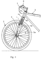
- the bicycle brake device 1 in one practical example of the present invention is for use on the front wheel, for example, and exerts a braking force by pressing against both side surfaces 5a of the rim of a front wheel 2.
- the brake device 1 is rotatably linked to the middle of a front fork 4.
- the front fork 4 is an air/oil or elastomer type of suspension, for example, and serves to absorb shocks from the road.
- the front fork 4 has a pair of suspension components 4a, an attachment component 4b to which the pair of suspension components 4a is attached, and a brake arch 4c that is used to reinforce the suspension components 4a.
- the brake arch 4c is in a roughly inverted U-shape that branches in two, and the lower ends thereof are fixed to the middle of the suspension components 4a.
- the brake device 1 is linked to the end of a brake cable 10 that extends from a brake lever 7 provided to a handlebar 6. As shown in Figures 1 and 2, the brake device 1 has a brake arm 12a that is fixed to the end of the inner cable 10b of the brake cable 10, and a brake arm 12b that is arranged in left-and-right symmetry with the brake arm 12a. To the upper end of the brake arm 12b is rotatably linked a linking arm 11 that is in contact with the outer cable 10a of the brake cable 10 and that extends to the inside. Both brake arms 12a and 12b are in an elongated S-shape that bows in and out from top to bottom.
- the lower ends of the brake arms 12a and 12b are rotatably supported by fixing pins 13a and 13b via link bases 14a and 14b (only 14a is shown in the figure).
- link bases 14a and 14b (only 14a is shown in the figure).
- the terms “upper,” “lower,” “inner,” and “outer” are to be determined by reference to Figure 2.
- the members described below, including the fixing pins 13a and 13b, are members in left-and-right symmetry, so only the right-side members in Figure 2 will be described below, and the description of the left-side members will be omitted.
- the fixing pin 13a is a stepped pin that protrudes forward from a seat 15a provided to the lower inside of the brake arch 4c.
- three support holes 16a are formed vertically at an equal radius around the axis of the fixing pin 13a in the inner surface of the seat 15a. These support holes 16a are used to adjust the strength of the return spring in an ordinary cantilevered brake device.
- a link base 14a is supported by the fixing pin 13a.
- the link base 14a has a cylindrical component 17a that is arranged around the outside of the fixing pin 13a and whose base end is in contact with the stepped portion 13c of the fixing pin 13a; an engagement component 18a that is fitted into and fixed around the outside of the base end of the cylindrical component 17a; and a teardrop-shaped arm component 19a that is fitted into and fixed around the outside of the tip.
- the brake arm 12a is rotatably supported by this cylindrical component 17a.
- the engagement component 18a is a roughly triangular member, as shown in Figure 5, and the inner side thereof is provided with an engagement pin 20a that goes through one of the support holes 16a. When this engagement pin 20a is inserted into a support hole 16a, the link base 14a is maintained at the specified attachment attitude.
- a spring holder 21a is provided between the brake arm 12a and the engagement component 18a.
- the spring holder 21a has a groove 22a that is formed in the circumferential direction, and an adjustment component 23a ( Figure 5) that is arranged around the outside.
- the base end of a return spring 24a is wound and fixed around the inside of the groove 22a.
- the tip of the return spring 24a extends upward and is engaged by an engagement pin 25a ( Figure 3) that protrudes from the rear surface in the middle portion of the brake arm 12a.
- the return spring 24a is energized such that the brake arm 12a rotates outward.
- An adjustment screw 27a that can come into contact with a protrusion 26a formed around the outside of the engagement component 18a is threaded into the adjustment component 23a.
- the energization of the left and right brake arms 12a and 12b can be adjusted, and the gap between the left and right brake shoes 30a and 30b (discussed below) and the rim side surface 5a can also be adjusted depending on how far in this adjustment screw 27a is threaded.
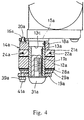
- a pair of lock nuts 28a and 29a ( Figure 4) are threaded between the brake arm 12a and the arm component 19a. These lock nuts 28a and 29a serve to restrict movement in the axial direction of the brake arm 12a.
- An attachment bolt 31a is tightened to the tip of the fixing pin 13a. This attachment bolt 31a serves to limit movement in the axial direction of the link base 14a.
- a shoe fixing link 32a that is used to attach the brake shoe 30a to the rear of the device 1 is attached roughly horizontally to the middle portion (in the vertical direction) of the brake arm 12a.
- the shoe fixing link 32a is rotatably linked to the brake arm 12a by an attachment pin 33a that goes through the two.
- the shoe fixing link 32a has an arm attachment component 34a that is formed in a U-shape so as to sandwich both sides of the brake arm 12a, and a shoe attachment component 35a that extends at a right angle from the arm attachment component 34a.
- the arm attachment component 34a In the arm attachment component 34a are formed an attachment hole 36a through which pass two U-shaped pieces used to attach the attachment pin 33a, and a fixing hole 37a that is used to fix a support pin 38a.
- the support pin 38a serves to rotatably support an auxiliary link 39a (discussed below).
- a shoe attachment slot 40a that is longer in the vertical direction (the depth direction of the paper in Figure 6) is formed in the shoe attachment component 35a. As shown in Figure 3, this shoe attachment slot 40a is formed such that the distance L between the rear end of the brake shoe 30a and the stepped portion 13c of the fixing pin 13a is at least 25 mm.
- the shoe attachment slot 40a is arranged in this position, the braking center approaches the center of the front fork 4, and there is a lower moment produced by reaction force. As a result, the force acting on the front fork 4 is weaker and the rigidity of the brake device is higher.
- the auxiliary link 39a is a flat member, the upper end of which is rotatably linked to the front surface of the arm attachment component 34a of the shoe fixing link 32a by the support pin 38a.
- the lower end is rotatably linked to the link base 14a by a support pin 41a attached to the tip of the arm component 19a.
- the distance from the axis of the fixing pin 13a to the axis of the support pin 41a is equal to the distance from the axis of the attachment pin 33a to the axis of the support pin 38a. Also, the distance from the axis of the support pin 38a arranged on both sides of the auxiliary link 39a to the axis of the support pin 41a is equal to the distance from the axis of the fixing pin 13a to the axis of the attachment pin 33a.
- these four pins are arranged such that they form the apexes of a parallelogram, and a linking mechanism is made up of part of the brake arm 12a, the link base 14a, part of the shoe fixing link 32a, and the auxiliary link 39a between these pins. Accordingly, the shoe fixing link 32a moves parallel to a line segment that connects the axis of the fixing pin 13a with the axis of the support pin 41a.
- the brake shoe 30a is inserted into the shoe attachment slot 40a.
- the brake shoe 30a has a shoe fixing pin 45a, a shoe holder 46a that is fixed to the tip of the shoe fixing pin 45a, and a rubbing pad 47a made of an elastic material and attached to the shoe holder 46a.
- the shoe fixing pin 45a is a round-head bolt with a hexagonal hole in it, and a convex washer 48a that has a convex surface forming a partial sphere and a concave washer 49a that has a concave surface which engages with the convex surface are arranged between the round-head and the shoe attachment component 35a, and between the shoe holder 46a and the shoe attachment component 35a.
- the vertical position and slope of the brake shoe 30a can be freely adjusted so as to match up with the position and slope of the side surface 5a of the rim 5.
- auxiliary links 39a and 39b are arranged on the inside of the brake arms 12a and 12b, the dimensions of the brake device 1 in its width direction are compact. As a result, the brake device 1 will not stick out from the front fork 4, for example, and hit the leg, etc., of the rider during operation. Furthermore, even if a reaction force is exerted on the rubbing pads 47a and 47b, the proper attitude of the link bases 14a and 14b will be preserved by the engagement pins 20a and 20b, so sufficient braking force will be obtained.
- the brake shoe 30a was located at the rear of the brake device 1, but it may also be located at the front.
- the auxiliary links 39a and 39b may be located on the inside of the brake arms 12a and 12b, but they may also be located on the outside, as shown in Figure 8.
- the four pins may be located at the apexes of a parallelogram, but instead of having them positioned the apexes of a parallelogram, they may each be varied in length such that the tips of the brake shoes 30a and 30b follow along the side surfaces 5a of the rim 5.
- the brake device 1 may be attached to either the rear fork or the front fork. As shown in Figure 9, both sides of the shoe fixing link 32a may be sandwiched by the brake arm 12a.
Landscapes
- Engineering & Computer Science (AREA)
- Mechanical Engineering (AREA)
- Braking Arrangements (AREA)
Priority Applications (1)
| Application Number | Priority Date | Filing Date | Title |
|---|---|---|---|
| EP00106929A EP1010611B1 (de) | 1995-03-07 | 1996-03-07 | Fahrradbremsvorrichtung |
Applications Claiming Priority (6)
| Application Number | Priority Date | Filing Date | Title |
|---|---|---|---|
| JP47494/95 | 1995-03-07 | ||
| JP04749495A JP3422588B2 (ja) | 1995-03-07 | 1995-03-07 | 自転車用ブレーキ装置 |
| JP04749395A JP3284018B2 (ja) | 1995-03-07 | 1995-03-07 | 自転車用ブレーキ装置 |
| JP4749395 | 1995-03-07 | ||
| JP4749495 | 1995-03-07 | ||
| JP47493/95 | 1995-03-07 |
Related Child Applications (2)
| Application Number | Title | Priority Date | Filing Date |
|---|---|---|---|
| EP00106929A Division EP1010611B1 (de) | 1995-03-07 | 1996-03-07 | Fahrradbremsvorrichtung |
| EP00106929.3 Division-Into | 2000-03-31 |
Publications (3)
| Publication Number | Publication Date |
|---|---|
| EP0731018A2 true EP0731018A2 (de) | 1996-09-11 |
| EP0731018A3 EP0731018A3 (de) | 1997-07-02 |
| EP0731018B1 EP0731018B1 (de) | 2002-07-03 |
Family
ID=26387668
Family Applications (2)
| Application Number | Title | Priority Date | Filing Date |
|---|---|---|---|
| EP00106929A Expired - Lifetime EP1010611B1 (de) | 1995-03-07 | 1996-03-07 | Fahrradbremsvorrichtung |
| EP96301564A Expired - Lifetime EP0731018B1 (de) | 1995-03-07 | 1996-03-07 | Fahrradbremsvorrichtung |
Family Applications Before (1)
| Application Number | Title | Priority Date | Filing Date |
|---|---|---|---|
| EP00106929A Expired - Lifetime EP1010611B1 (de) | 1995-03-07 | 1996-03-07 | Fahrradbremsvorrichtung |
Country Status (3)
| Country | Link |
|---|---|
| US (1) | US5636716A (de) |
| EP (2) | EP1010611B1 (de) |
| DE (2) | DE69622064T2 (de) |
Cited By (4)
| Publication number | Priority date | Publication date | Assignee | Title |
|---|---|---|---|---|
| GB2326204A (en) * | 1996-12-05 | 1998-12-16 | Dia Compe | Adjustable bicycle brake |
| EP0967144A3 (de) * | 1998-06-22 | 2000-06-21 | Shimano Inc. | Fahrrad-Bremsgerät |
| EP0967145A3 (de) * | 1998-06-22 | 2002-07-31 | Shimano Inc. | Fahrradbremse mit von Hebelelementen nachgestellten Bremsschuhen |
| EP0960807A3 (de) * | 1998-05-27 | 2003-01-02 | Shimano Inc. | Fahrradbremsmontageanordnung |
Families Citing this family (24)
| Publication number | Priority date | Publication date | Assignee | Title |
|---|---|---|---|---|
| JP3323403B2 (ja) * | 1996-09-18 | 2002-09-09 | 株式会社シマノ | 自転車用ブレーキ装置 |
| TW334994U (en) * | 1997-01-24 | 1998-06-21 | Falcon Cycle Parts Co Ltd | Bi-level activating braking system |
| US5924525A (en) * | 1997-04-16 | 1999-07-20 | Shimano Inc. | Bicycle brake assembly |
| US5896956A (en) * | 1997-05-06 | 1999-04-27 | Ah-Ping Lin | Bicycle brake device |
| US5979608A (en) * | 1997-06-26 | 1999-11-09 | Shimano Inc. | Reinforced booster for bicycle brake |
| US5913387A (en) | 1997-07-16 | 1999-06-22 | Shimano Inc. | Brake device |
| US5894913A (en) * | 1997-07-17 | 1999-04-20 | Shimano Inc. | Bicycle brake assembly |
| US6079523A (en) * | 1997-09-17 | 2000-06-27 | Irvine; Mark W. | Bicycle hand brake |
| USD427124S (en) * | 1998-02-09 | 2000-06-27 | Shimano Inc. | Bicycle brake unit |
| US6003638A (en) * | 1998-03-02 | 1999-12-21 | Shimano Inc. | Bicycle brake device |
| CN1323269A (zh) | 1998-08-31 | 2001-11-21 | 布莱阿姆青年大学 | 带有靴座定位柔性件的制动装置 |
| US6125973A (en) * | 1998-12-29 | 2000-10-03 | Irvine; Mark W. | Brake pad holder |
| US6264008B1 (en) * | 1999-04-09 | 2001-07-24 | Sram Corporation | Parallel-push brake mechanism for bicycles |
| US6336526B1 (en) * | 2000-03-23 | 2002-01-08 | Tzu-Chieh Chou | Bicycle disk brake |
| US6386329B1 (en) | 2000-06-14 | 2002-05-14 | Shimano Inc. | Bicycle brake shoe |
| US6757975B1 (en) | 2001-01-25 | 2004-07-06 | Brigham Young University | Multi-layered compliant mechanisms and method of manufacture |
| US6607185B2 (en) * | 2001-10-17 | 2003-08-19 | Answer Products, Inc. | Suspension fork having reserved arch |
| US8056682B2 (en) * | 2007-08-06 | 2011-11-15 | Chang Hui Lin | Bicycle brake device |
| US8066104B2 (en) * | 2009-03-19 | 2011-11-29 | Specialized Bicycle Components, Inc. | Bicycle brake assembly |
| US20130341129A1 (en) * | 2012-06-26 | 2013-12-26 | Shimano Inc. | Bicycle brake arm |
| US9457867B2 (en) | 2013-03-14 | 2016-10-04 | Specialized Bicycle Components, Inc. | Bicycle brake assembly |
| US9340255B2 (en) * | 2014-09-30 | 2016-05-17 | Tektro Technology Corp | Adjustable shoe mounting structure for bicycle brake device |
| US20170191534A1 (en) * | 2016-01-06 | 2017-07-06 | Shimano Inc. | Bicycle disc brake caliper |
| US11008034B2 (en) | 2017-01-03 | 2021-05-18 | Innovation Lab, LLC | Child medical transport apparatus, assembly and method thereof |
Family Cites Families (5)
| Publication number | Priority date | Publication date | Assignee | Title |
|---|---|---|---|---|
| FR895049A (fr) * | 1943-05-27 | 1945-01-12 | Freins pour cycles et toutes autres applications | |
| FR909871A (fr) * | 1944-11-08 | 1946-05-21 | Frein sur jante à mouvement parallèle | |
| GB616123A (en) * | 1944-11-08 | 1949-01-17 | Marcel Paul Durand | Rim brake |
| US3921764A (en) * | 1973-07-25 | 1975-11-25 | William R Mathauser | Self-energizing bicycle brake |
| DE9307514U1 (de) * | 1993-05-18 | 1993-07-22 | Jochem, Martin, 78333 Stockach | Felgenbremse für Mountainbike- und Trekkingfahrräder ohne geteilten Bremszug |
-
1996
- 1996-03-06 US US08/612,453 patent/US5636716A/en not_active Expired - Lifetime
- 1996-03-07 DE DE69622064T patent/DE69622064T2/de not_active Expired - Lifetime
- 1996-03-07 EP EP00106929A patent/EP1010611B1/de not_active Expired - Lifetime
- 1996-03-07 EP EP96301564A patent/EP0731018B1/de not_active Expired - Lifetime
- 1996-03-07 DE DE69622207T patent/DE69622207T2/de not_active Expired - Lifetime
Cited By (7)
| Publication number | Priority date | Publication date | Assignee | Title |
|---|---|---|---|---|
| US6155383A (en) * | 1996-06-11 | 2000-12-05 | Shimano, Inc. | Bicycle brake device |
| GB2326204A (en) * | 1996-12-05 | 1998-12-16 | Dia Compe | Adjustable bicycle brake |
| EP0960807A3 (de) * | 1998-05-27 | 2003-01-02 | Shimano Inc. | Fahrradbremsmontageanordnung |
| EP0967144A3 (de) * | 1998-06-22 | 2000-06-21 | Shimano Inc. | Fahrrad-Bremsgerät |
| EP0967145A3 (de) * | 1998-06-22 | 2002-07-31 | Shimano Inc. | Fahrradbremse mit von Hebelelementen nachgestellten Bremsschuhen |
| CN1090579C (zh) * | 1998-06-22 | 2002-09-11 | 株式会社岛野 | 自行车制动装置 |
| CZ296794B6 (cs) * | 1998-06-22 | 2006-06-14 | Shimano Inc | Brzdové zarízení |
Also Published As
| Publication number | Publication date |
|---|---|
| EP1010611A3 (de) | 2000-09-20 |
| DE69622207D1 (de) | 2002-08-08 |
| DE69622064T2 (de) | 2003-03-13 |
| EP1010611A2 (de) | 2000-06-21 |
| EP1010611B1 (de) | 2002-07-03 |
| DE69622064D1 (de) | 2002-08-08 |
| EP0731018A3 (de) | 1997-07-02 |
| DE69622207T2 (de) | 2003-03-06 |
| US5636716A (en) | 1997-06-10 |
| EP0731018B1 (de) | 2002-07-03 |
Similar Documents
| Publication | Publication Date | Title |
|---|---|---|
| EP1010611B1 (de) | Fahrradbremsvorrichtung | |
| US5901974A (en) | Bicycle, anti-dive braking system | |
| US5655630A (en) | Bicycle brake device | |
| US5819880A (en) | Bicycle brake shoe holder | |
| EP0397940B1 (de) | Fahrradbremse | |
| US7537094B1 (en) | Self-adjusting bicycle brake assembly | |
| US3114434A (en) | Rim brake | |
| US6454055B1 (en) | Braking device with shoe-orienting compliant member | |
| US6079523A (en) | Bicycle hand brake | |
| EP0189194B1 (de) | Fahrradfelgenbremsanlage | |
| RU2218287C2 (ru) | Узел рукоятки тормоза (варианты) | |
| US5908089A (en) | Cantilever brake device | |
| RU2242396C2 (ru) | Тормозное устройство велосипеда | |
| US20040011598A1 (en) | Bicycle brake device | |
| US6003638A (en) | Bicycle brake device | |
| JP3422588B2 (ja) | 自転車用ブレーキ装置 | |
| KR900001347B1 (ko) | 차량용 브레이크 장치 | |
| JPH08239076A (ja) | 自転車用ブレーキ装置 | |
| US5615753A (en) | Brake assembly for a bicycle | |
| JP3159551U (ja) | 自転車用ブレーキ装置 | |
| CZ9800594A3 (cs) | Brzdová souprava pro bicykly | |
| EP0791530B1 (de) | Mittelzugbremse | |
| KR0118018B1 (ko) | 자동차용 주차 브레이크 케이블 장력 자동조절장치 | |
| US20010027901A1 (en) | Brake apparatus for a bicycle and bicycle comprising this apparatus | |
| EP0174041B1 (de) | Fahrradbremse mit einander gegenüber liegenden tangentiell bewegbaren Bremsblockhebeln |
Legal Events
| Date | Code | Title | Description |
|---|---|---|---|
| PUAI | Public reference made under article 153(3) epc to a published international application that has entered the european phase |
Free format text: ORIGINAL CODE: 0009012 |
|
| AK | Designated contracting states |
Kind code of ref document: A2 Designated state(s): DE FR GB IT |
|
| PUAL | Search report despatched |
Free format text: ORIGINAL CODE: 0009013 |
|
| AK | Designated contracting states |
Kind code of ref document: A3 Designated state(s): DE FR GB IT |
|
| 17P | Request for examination filed |
Effective date: 19970531 |
|
| 17Q | First examination report despatched |
Effective date: 19980915 |
|
| GRAG | Despatch of communication of intention to grant |
Free format text: ORIGINAL CODE: EPIDOS AGRA |
|
| GRAG | Despatch of communication of intention to grant |
Free format text: ORIGINAL CODE: EPIDOS AGRA |
|
| GRAH | Despatch of communication of intention to grant a patent |
Free format text: ORIGINAL CODE: EPIDOS IGRA |
|
| GRAH | Despatch of communication of intention to grant a patent |
Free format text: ORIGINAL CODE: EPIDOS IGRA |
|
| GRAA | (expected) grant |
Free format text: ORIGINAL CODE: 0009210 |
|
| AK | Designated contracting states |
Kind code of ref document: B1 Designated state(s): DE FR GB IT |
|
| REF | Corresponds to: |
Ref document number: 69622064 Country of ref document: DE Date of ref document: 20020808 |
|
| ET | Fr: translation filed | ||
| PLBE | No opposition filed within time limit |
Free format text: ORIGINAL CODE: 0009261 |
|
| STAA | Information on the status of an ep patent application or granted ep patent |
Free format text: STATUS: NO OPPOSITION FILED WITHIN TIME LIMIT |
|
| 26N | No opposition filed |
Effective date: 20030404 |
|
| PGFP | Annual fee paid to national office [announced via postgrant information from national office to epo] |
Ref country code: GB Payment date: 20060301 Year of fee payment: 11 |
|
| GBPC | Gb: european patent ceased through non-payment of renewal fee |
Effective date: 20070307 |
|
| PG25 | Lapsed in a contracting state [announced via postgrant information from national office to epo] |
Ref country code: GB Free format text: LAPSE BECAUSE OF NON-PAYMENT OF DUE FEES Effective date: 20070307 |
|
| PGFP | Annual fee paid to national office [announced via postgrant information from national office to epo] |
Ref country code: IT Payment date: 20100319 Year of fee payment: 15 Ref country code: FR Payment date: 20100324 Year of fee payment: 15 |
|
| PGFP | Annual fee paid to national office [announced via postgrant information from national office to epo] |
Ref country code: DE Payment date: 20110302 Year of fee payment: 16 |
|
| REG | Reference to a national code |
Ref country code: FR Ref legal event code: ST Effective date: 20111130 |
|
| PG25 | Lapsed in a contracting state [announced via postgrant information from national office to epo] |
Ref country code: FR Free format text: LAPSE BECAUSE OF NON-PAYMENT OF DUE FEES Effective date: 20110331 |
|
| PG25 | Lapsed in a contracting state [announced via postgrant information from national office to epo] |
Ref country code: IT Free format text: LAPSE BECAUSE OF NON-PAYMENT OF DUE FEES Effective date: 20110307 |
|
| REG | Reference to a national code |
Ref country code: DE Ref legal event code: R119 Ref document number: 69622064 Country of ref document: DE Effective date: 20121002 |
|
| PG25 | Lapsed in a contracting state [announced via postgrant information from national office to epo] |
Ref country code: DE Free format text: LAPSE BECAUSE OF NON-PAYMENT OF DUE FEES Effective date: 20121002 |