EP0731255B1 - Verfahren zum Betrieb einer Kraftwerksanlage - Google Patents
Verfahren zum Betrieb einer Kraftwerksanlage Download PDFInfo
- Publication number
- EP0731255B1 EP0731255B1 EP96810095A EP96810095A EP0731255B1 EP 0731255 B1 EP0731255 B1 EP 0731255B1 EP 96810095 A EP96810095 A EP 96810095A EP 96810095 A EP96810095 A EP 96810095A EP 0731255 B1 EP0731255 B1 EP 0731255B1
- Authority
- EP
- European Patent Office
- Prior art keywords
- steam
- combustion chamber
- turbine
- gas
- heat
- Prior art date
- Legal status (The legal status is an assumption and is not a legal conclusion. Google has not performed a legal analysis and makes no representation as to the accuracy of the status listed.)
- Expired - Lifetime
Links
Images


Classifications
-
- F—MECHANICAL ENGINEERING; LIGHTING; HEATING; WEAPONS; BLASTING
- F01—MACHINES OR ENGINES IN GENERAL; ENGINE PLANTS IN GENERAL; STEAM ENGINES
- F01K—STEAM ENGINE PLANTS; STEAM ACCUMULATORS; ENGINE PLANTS NOT OTHERWISE PROVIDED FOR; ENGINES USING SPECIAL WORKING FLUIDS OR CYCLES
- F01K21/00—Steam engine plants not otherwise provided for
- F01K21/04—Steam engine plants not otherwise provided for using mixtures of steam and gas; Plants generating or heating steam by bringing water or steam into direct contact with hot gas
- F01K21/042—Steam engine plants not otherwise provided for using mixtures of steam and gas; Plants generating or heating steam by bringing water or steam into direct contact with hot gas pure steam being expanded in a motor somewhere in the plant
-
- F—MECHANICAL ENGINEERING; LIGHTING; HEATING; WEAPONS; BLASTING
- F01—MACHINES OR ENGINES IN GENERAL; ENGINE PLANTS IN GENERAL; STEAM ENGINES
- F01K—STEAM ENGINE PLANTS; STEAM ACCUMULATORS; ENGINE PLANTS NOT OTHERWISE PROVIDED FOR; ENGINES USING SPECIAL WORKING FLUIDS OR CYCLES
- F01K21/00—Steam engine plants not otherwise provided for
- F01K21/04—Steam engine plants not otherwise provided for using mixtures of steam and gas; Plants generating or heating steam by bringing water or steam into direct contact with hot gas
- F01K21/047—Steam engine plants not otherwise provided for using mixtures of steam and gas; Plants generating or heating steam by bringing water or steam into direct contact with hot gas having at least one combustion gas turbine
-
- F—MECHANICAL ENGINEERING; LIGHTING; HEATING; WEAPONS; BLASTING
- F02—COMBUSTION ENGINES; HOT-GAS OR COMBUSTION-PRODUCT ENGINE PLANTS
- F02C—GAS-TURBINE PLANTS; AIR INTAKES FOR JET-PROPULSION PLANTS; CONTROLLING FUEL SUPPLY IN AIR-BREATHING JET-PROPULSION PLANTS
- F02C6/00—Plural gas-turbine plants; Combinations of gas-turbine plants with other apparatus; Adaptations of gas-turbine plants for special use
- F02C6/003—Gas-turbine plants with heaters between turbine stages
-
- F—MECHANICAL ENGINEERING; LIGHTING; HEATING; WEAPONS; BLASTING
- F05—INDEXING SCHEMES RELATING TO ENGINES OR PUMPS IN VARIOUS SUBCLASSES OF CLASSES F01-F04
- F05D—INDEXING SCHEME FOR ASPECTS RELATING TO NON-POSITIVE-DISPLACEMENT MACHINES OR ENGINES, GAS-TURBINES OR JET-PROPULSION PLANTS
- F05D2260/00—Function
- F05D2260/20—Heat transfer, e.g. cooling
- F05D2260/232—Heat transfer, e.g. cooling characterized by the cooling medium
- F05D2260/2322—Heat transfer, e.g. cooling characterized by the cooling medium steam
-
- Y—GENERAL TAGGING OF NEW TECHNOLOGICAL DEVELOPMENTS; GENERAL TAGGING OF CROSS-SECTIONAL TECHNOLOGIES SPANNING OVER SEVERAL SECTIONS OF THE IPC; TECHNICAL SUBJECTS COVERED BY FORMER USPC CROSS-REFERENCE ART COLLECTIONS [XRACs] AND DIGESTS
- Y02—TECHNOLOGIES OR APPLICATIONS FOR MITIGATION OR ADAPTATION AGAINST CLIMATE CHANGE
- Y02T—CLIMATE CHANGE MITIGATION TECHNOLOGIES RELATED TO TRANSPORTATION
- Y02T50/00—Aeronautics or air transport
- Y02T50/60—Efficient propulsion technologies, e.g. for aircraft
Definitions
- the present invention relates to a method of operation a power plant according to the preamble of claim 1.
- EP-0 462 458 A1 which essentially consists of a gas turbine group, a downstream heat recovery steam generator and an injector system consists.
- the gas turbine group mentioned as an autonomous unit consists of one generator, one Compressor, a combustion chamber and a turbine.
- the exhaust gases from the turbine are fed to the heat recovery steam generator where they continue to be used energetically.
- the waste heat steam generator From the released Thermal energy from these exhaust gases is in a high pressure section the waste heat steam generator generates a high pressure steam, which is supplied to the injector system mentioned, and there the propellant nozzle is applied.
- this Injector system is a compressed air from the compressor initiated: This air is caused by the action from the propellant nozzle further compressed.
- a power plant has become known from WO-A-94/28285, which essentially consists of a gas turbine group with a downstream heat recovery steam generator consists.
- the turbo group itself consists of a compressor, from a first and second combustion chamber, each with an intermediate one Turbines.
- the exhaust gases from the last turbine flow through the heat recovery steam generator and the amount of steam produced there is blown into the gas turbine group, here preferably in the combustion chambers.
- Heat recovery steam generators gradually produce different steam qualities, for which exergetically would be counterproductive, for example holistically to prepare superheated steam.
- the steam generation proposed here therefore works and their injection into the gas turbine group is refined too little, in particular when it comes to gas turbine groups with sequential combustion acts, because it can not optimize efficiency and none Achieve quick responsiveness to load changes.
- the invention seeks to remedy this.
- the invention how it is characterized in the claims, the task lies based on a procedure of the type mentioned at the beginning Efficiency and specific performance through feedback of steam quantities in the gas turbine group.
- the basic circuit of the gas turbine group is sequential Combustion designed.
- Such a gas turbine group is surprisingly particularly suitable for the blowing in of a downstream heat recovery steam generator generated steam in their circuit.
- the one here achievable performances are, depending on the circulatory arrangement a factor of two to three over the performance of such Gas turbine group without steam injection.
- a major advantage of the invention is that that the specific cost of having such a gas turbine group Steam injection much lower than that of a combination system fail, which results in very lucrative perspectives.
- Another advantage of the invention is that the water consumption of such a system is only about two thirds of a modern steam cycle plant with a wet cooling tower amounts to; the water consumption of this plant is approximately in the same order of magnitude as that of a combination system Power. It is true that the water for this must be subjected to a partial reprocessing, the costs of which but are so insignificant that they reduce the cost of electricity practically do not affect.
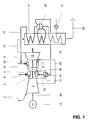
- Fig. 1 shows a gas turbine group, which with a heat recovery steam generator 14 is in operative connection, the one in this Heat recovery steam generator 14 provided steam at a suitable one Point is blown into the gas turbine group.
- the necessary fuel can be, for example, with a Interacting coal gasification gas turbine group provided become.
- used fuels from a primary network Respectively. Will supply a gaseous fuel provided for the operation of the gas turbine group via a pipeline, so the potential from the pressure and / or temperature difference between primary network and consumer network for the concerns the gas turbine group, or generally the system, recuperated become.
- the gas turbine group exists as an autonomous unit from a compressor 1, one downstream of the compressor 1 first combustion chamber 4, one downstream of this combustion chamber 4 first turbine 7, one of these turbine 7 downstream second combustion chamber 9 and one of these combustion chambers 9 downstream second turbine 12.
- the flow machines mentioned 1, 7, 12 have a uniform rotor shaft 24 on, which by an invisible coupling with the also not visible shaft of a generator 19 coupled is.
- This rotor shaft 24 is preferably two Bearings not shown, which is located at the top of the compressor 1 and are placed downstream of the second turbine 12.
- the compressor stage can be, for example, around to increase specific performance in two not shown Partial compressor can be divided.
- the air sucked in 2 flows after their compression preferably into a not shown Housing that exits the compressor and the includes first turbine 7.
- the first combustion chamber 4 housed, which preferably as coherent annular combustion chamber is formed and wherein the compressed air 3 flows in.
- the compressed air to the first combustion chamber 4 from a not shown Air storage system can be provided.
- the ring combustion chamber 4 has a number on the head side, distributed over the circumference Burner, not shown, on the combustion maintain. As such, diffusion burners can be used here Get involved.
- the annular combustion chamber 4 consist of a number of individual tubular combustion chambers, which are at most oblique, sometimes also helical, are arranged around the rotor axis. This ring combustion chamber 4, regardless of its design, will and can be geometric arranged so that they match the rotor length has virtually no influence.
- the hot gases 6 from this ring combustion chamber 4 act on the immediately downstream first turbine 7, whose caloric relaxing effect on the hot gases 6 is deliberately kept to a minimum, i.e. this turbine 7 is accordingly consist of no more than one or two rows of blades.
- This turbine 7 will need one Pressure equalization on the end faces to stabilize the Provide axial thrust.
- the partially relaxed in turbine 7 are called exhaust gases 8, which are directly in the second combustion chamber 9 stream, for reasons explained, they are quite high Temperature, preferably it is operationally specific to interpret that it is still around 1000 ° C.
- This second combustion chamber 9 has essentially the shape of a coherent annular axial or quasi-axial cylinder; this combustion chamber 9 can of course also be made of a number axially, quasi-axially or helically arranged and exist in self-contained combustion chambers. What the configuration of the annular, from a single combustion chamber Existing combustion chamber 9, are in the circumferential direction this annular cylinder has multiple fuel lances disposes, which symbolizes in FIG. 1 with arrow 10 are, of course, they don't have one Ring line shown can be connected to each other.
- This Combustion chamber 9 has no burner per se: the combustion of the hot exhaust gases 8 coming from the turbine 7 injected fuel 10 happens here by auto-ignition, as far as the temperature level is such a type of operation allows.
- this combustion chamber 9 preferably the inner and outer wall, arranged in the circumferential direction, a series of vortex generators, not shown in the figure provided, which is preferably in the axial direction are placed upstream of the fuel lances 10.
- the task of these vortex generators is to create vortexes which is a backflow zone, analogous to that from the premix burners in the annular combustion chamber 4. Since it is this combustion chamber 9, due to the axial arrangement and the Length, is a high-speed combustion chamber, whose average speed is greater than approx. 60 m / s, the vortex generating elements, i.e. the vortex generators, be designed to conform to the flow.
- the vortex producing Elements can either be on the outside surface or on be placed on the inner surface of the combustion chamber 5, or both Act.
- the crooked areas between the outside and internal vortex generating elements are preferred arranged in mirror image, such that the Flow cross section in the combustion chamber 9 downstream of this location in the area of the injection of the fuel 10 a vortex generating Experiencing expansion.
- you can the vortex-generating elements are also shifted axially to one another be.
- the downstream surface of the vortex generating Elements is essentially radial, so that from there a backflow zone is set.
- the liquid auxiliary fuel fulfills the task, as it were, as Detonating cord, and then triggers a spontaneous ignition in the combustion chamber 9 when the hot exhaust gases 8 from the first turbine 7 a temperature below the target should be at optimal levels.
- This precaution To provide fuel oil to ensure auto-ignition, always proves to be particularly appropriate, if the gas turbine group is operated with a reduced load.
- This arrangement also makes a decisive contribution to that the combustion chamber 9 have a minimal axial extent can.
- the short length of the combustion chamber 9, the effect of the recognized vortex generators for flame stabilization as well as the continuous ensuring of auto-ignition are causally responsible for the combustion takes place very quickly, and the residence time of the fuel remains minimal in the area of the hot flame front.
- the second combustion chamber 9 between the outflow plane of the first turbine 7 and the inflow plane of the second turbine 12 takes a minimum length. Furthermore, since the relaxation of the hot gases 6 in the first Turbine 7, for reasons stated, over a few rows of moving blades happens, a gas turbine group can be provided, whose rotor shaft 24 due to its minimized Length can only be supported on two bearings, not shown is. On the compressor side, the rotor shaft 24 has a not shown Coupling on, which is used for power output. It is to increase the efficiency of the gas turbine group from Advantage if in front of the second combustion chamber 9 in the figure small visible diffuser is provided. In order to the total pressure loss in the overall system could be reduced.
- the compressor stages can be equipped with intermediate cooling.
- intermediate cooling the geometric Basic concept of the gas turbine group, as shown in the figure is set out not to alter, it is suggested to provide an intercooler, not shown in the figure, the inside of the stator housing and downstream the compressor stages is placed.
- the cooling this intercooler happens indirectly or directly.
- immediate intermediate cooling for example done by an aggregate whose operation is on Evaporation of the injected water is designed.
- the compressor air cooled in the heat exchanger 17 then serves as high-quality cooling air 26 for those with high calorific loads Aggregates of the plant.
- the figure here shows, for example Introduction of the cooling air 26 into the first turbine 7.
- the figure also shows a partial withdrawal of another compressor air 23, which is used as cooling air for example for the second Turbine 12 is used.
- this compressor air 23 heat exchange can be accomplished in the above sense, by adding another heat exchanger that has the same function as the heat exchanger 17.
- the achievable achievements depend on Circuit arrangement by a factor of 2 to 2.5 over the power the gas turbine group without steam injection. Achieved the efficiency values that come very close to those which can be reached with the best combination systems.
- FIG. 2 shows an arrangement largely according to Fig. 1, wherein but here steam with preferably supercritical pressure is used reached.
- the exhaust gases 13 from the second turbine 12 flow through a heat recovery steam generator 28 here, too has no drum.
- the resulting overheated Steam 29 first acts on a steam turbine 30, which is connected to the rotor shaft 24 via a gear 33 is. A part of the flows from the steam turbine 30 Counterpressure steam 31 directly in the narrower or wider area the first combustion chamber 4, while another part of the Back pressure steam 32 the same superheating according to FIG.
- Fig. 4 shows a further arrangement, which, although reduced specific work another remarkable increase in efficiency results.
- Part 34 of the back pressure steam 32 from the steam turbine is converted into an appropriately designed one Heat recovery steam generator 36 is recirculated and reheated there, before this steam 35 in a suitable place in the Gas turbine group is blown.
- the rest of the back pressure steam 32 is also overheated in the usual manner (cf. Fig. 1-3) and blown into the gas turbine group at a suitable point.
Landscapes
- Engineering & Computer Science (AREA)
- Chemical & Material Sciences (AREA)
- Combustion & Propulsion (AREA)
- Mechanical Engineering (AREA)
- General Engineering & Computer Science (AREA)
- Engine Equipment That Uses Special Cycles (AREA)
Description
- Fig. 1
- eine Schaltung einer Gasturbogruppe mit sequentieller Verbrennung, mit einem Abhitzedampferzeuger und einer Dampfeinblasung an geeigneter Stelle in die Gasturbogruppe,
- Fig. 2
- eine weitere Schaltung gemäss Fig. 1, mit modifizierter Dampfeinblasung,
- Fig. 3
- eine weitere Schaltung nach Fig. 1, mit einer dazwischen geschalteten Dampfturbine und
- Fig. 4
- eine weitere Schaltung gemäss Fig. 3, wobei der aus der Dampfturbine ausströmende Gegendruckdampf zwischenüberhitzt wird.
- 1
- Verdichter
- 2
- Angesaugte Luft
- 3
- Verdichtete Luft
- 4
- Erste Brennkammer
- 5
- Brennstoff, Brennstoffzuführung
- 6
- Heissgase
- 7
- Erste Turbine
- 8
- Heisse Abgase
- 9
- Zweite Brennkammer
- 10
- Brennstoff, Brennstoffzuführung, Brennstofflanze
- 11
- Heissgase
- 12
- Zweite Turbine
- 13
- Abgase
- 14
- Abhitzedampferzeuger
- 15
- Ueberhitzter Dampf
- 16
- Sattdampf
- 17
- Wärmetauscher
- 18
- Abgezweigte verdichtete Luft
- 19
- Generator
- 20
- Trommel
- 21
- Speisewasserpumpe
- 22
- Rauchgase
- 23
- Teil der Verdichterluft
- 24
- Rotorwelle
- 25
- Ueberhitzter Dampf
- 26
- Kühlluft
- 27
- Ueberhitzter Dampf
- 28
- Abhitzedampferzeuger
- 29
- Ueberhitzter Dampf
- 30
- Dampfturbine
- 31
- Gegendruckdampf
- 32
- Gegendruckdampf
- 33
- Getriebe
- 34
- Teil des Gegendruckdampfes 32
- 35
- Zwischenüberhitzter Dampf im Abhitzedampferzeuger
- 36
- Abhitzedampferzeuger
Claims (10)
- Verfahren zum Betrieb einer Kraftwerksanlage, welche im wesentlichen aus einer Gasturbogruppe und einem nachgeschalteten Abhitzedampferzeuger (14, 28, 36), der von Abgasen (13) aus der Gasturbogruppe durchströmt wird, besteht, wobei die Gasturbogruppe ihrerseits im wesentlichen aus einer Verdichtereinheit (1), einer stromab der Verdichtereinheit wirkenden ersten Brennkammmer (4), einer stromab der ersten Brennkammer wirkenden ersten Turbine (7), einer stromab der ersten Turbine wirkenden zweiten Brennkammer (9) und einer stromab der zweiten Brennkammer wirkenden zweiten Turbine (12) besteht, wobei die Brennkammern mit einem gasförmigen und/oder flüssigen Brennstoff (5, 10) betrieben werden und wobei ein Teil des in dem Abhitzedampferzeuger (14, 28, 36) produzierten überhitzten Dampfes (15, 27, 35) an geeigneter Stelle in die Gasturbogruppe eingeblasen wird, dadurch gekennzeichnet, dass der andere Teil des in dem Abhitzedampferzeuger (14, 28, 36) anfallenden Sattdampfes (16) und/oder eines anfallenden Gegendruckdampfes (32) über mindestens einen mit einer Verdichterluft (18) durchströmten Wärmetauscher (17) geleitet wird, und dass ein aus dem Wärmetauscher (17) anfallender überhitzter Dampf (25) ebenfalls an geeigneter Stelle in die Gasturbogruppe eingeblasen wird.
- Verfahren nach Anspruch 1, dadurch gekennzeichnet, dass mindestens ein Teil des in dem Abhitzedampferzeuger überhitzten Dampfes (15, 27, 35) dem Brennstoff (5, 10) mindestens einer Brennkammer (7, 12) beigemischt wird.
- Verfahren nach Anspruch 1, dadurch gekennzeichnet, dass mindestens ein Teil des in dem Abhitzedampferzeuger überhitzten Dampfes (15, 27, 35) in mindestens eine Brennkammer (7, 12) eingeleitet wird.
- Verfahren nach Anspruch 1, dadurch gekennzeichnet, dass mindestens ein Teil des in dem Abhitzedampferzeuger überhitzten Dampfes (15, 27, 35) oder des Sattdampfes (16) oder des Gegendruckdampfes (32) vorweg als Kühlmedium für die heissen Strukturen der Gasturbogruppe verwendet wird.
- Verfahren nach Anspruch 1, dadurch gekennzeichnet, dass mindestens ein Teil des überhitzten Dampfes (15, 27, 35) oder des Sattdampfes (16) oder des Gegendruckdampfes (32) als Treibmittel für die Eindüsung des Brennstoffes (5, 10) in die betreffende Brennkammer (7, 12) verwendet wird.
- Verfahren nach Anspruch 1, dadurch gekennzeichnet, dass der Gegendruckdampf (32) aus einer stromab des Abhitzedampferzeugers (28, 36) wirkenden Dampfturbine (30) strömt, welche mit mindestens einem Teil eines im Abhitzedampferzeuger (28, 36) anfallenden überhitzten Dampfes (29) betrieben wird.
- Verfahren nach Anspruch 6, dadurch gekennzeichnet, dass ein Teil des aus der Dampfturbine (30) ausströmenden Gegendruckdampfes (31) an geeigneter Stelle in die Gasturbogruppe eingeleitet wird.
- Verfahren nach Anspruch 6, dadurch gekennzeichnet, dass die Dampfturbine (30) als Bestandteil eines der Gasturbogruppe nachgeschalteten Dampfkreislaufes betrieben wird, und dass der Dampf dieses Dampfkreislaufes aus dem Abhitzedampferzeuger stammt, welcher mit den Abgasen aus der Gasturbogruppe betrieben wird.
- Verfahren nach Anspruch 1, dadurch gekennzeichnet, dass der aus dem ersten Wärmetauscher (17) anfallende überhitzte Dampf (25) in die erste Brennkammer (7) eingeleitet wird, und dass ein aus einem zweiten Wärmetauscher anfallende überhitzte Dampf in die zweite Brennkammer (12) eingeleitet wird.
- Verfahren nach Anspruch 1, dadurch gekennzeichnet, dass die zweite Brennkammer (9) durch Selbstzündung betrieben wird.
Applications Claiming Priority (2)
| Application Number | Priority Date | Filing Date | Title |
|---|---|---|---|
| DE19508018 | 1995-03-07 | ||
| DE19508018A DE19508018A1 (de) | 1995-03-07 | 1995-03-07 | Verfahren zum Betrieb einer Kraftwerksanlage |
Publications (2)
| Publication Number | Publication Date |
|---|---|
| EP0731255A1 EP0731255A1 (de) | 1996-09-11 |
| EP0731255B1 true EP0731255B1 (de) | 1999-05-26 |
Family
ID=7755907
Family Applications (1)
| Application Number | Title | Priority Date | Filing Date |
|---|---|---|---|
| EP96810095A Expired - Lifetime EP0731255B1 (de) | 1995-03-07 | 1996-02-16 | Verfahren zum Betrieb einer Kraftwerksanlage |
Country Status (5)
| Country | Link |
|---|---|
| US (1) | US5689948A (de) |
| EP (1) | EP0731255B1 (de) |
| JP (1) | JPH08246897A (de) |
| CN (1) | CN1143052C (de) |
| DE (2) | DE19508018A1 (de) |
Cited By (1)
| Publication number | Priority date | Publication date | Assignee | Title |
|---|---|---|---|---|
| WO2003029618A1 (de) | 2001-10-01 | 2003-04-10 | Alstom Technology Ltd. | Verfahren und vorrichtung zum anfahren von emissionsfreien gasturbinenkraftwerken |
Families Citing this family (44)
| Publication number | Priority date | Publication date | Assignee | Title |
|---|---|---|---|---|
| DE19651882A1 (de) * | 1996-12-13 | 1998-06-18 | Asea Brown Boveri | Verfahren zur Frequenzstützung beim Betrieb einer Kraftwerksanlage |
| DE19654472A1 (de) * | 1996-12-27 | 1998-07-02 | Asea Brown Boveri | Verfahren zur Kühlung von thermisch hochbelasteten Aggregaten einer Gasturbogruppe |
| EP0899438B1 (de) * | 1997-08-25 | 2002-05-29 | Alstom | Gasturbine mit Wärmerückgewinnungserzeuger von überhitztem Dampf zum Einspritzen in die Brennkammer und von Sattdampf zum Kühlen und dann Einspritzen in die Brennkammer |
| AU2172500A (en) | 1998-12-11 | 2000-06-26 | Allied-Signal Inc. | Power generation system, and heat exchanger and operating method for a power generation system |
| EP1013879A1 (de) | 1998-12-24 | 2000-06-28 | Asea Brown Boveri AG | Flüssigkeitsgekühlte Turbomaschinenwelle |
| DE19900026B4 (de) * | 1999-01-02 | 2016-01-21 | Alstom Technology Ltd. | Gasturbine mit Dampfeindüsung |
| DE10041413B4 (de) | 1999-08-25 | 2011-05-05 | Alstom (Switzerland) Ltd. | Verfahren zum Betrieb einer Kraftwerksanlage |
| DE19961383A1 (de) * | 1999-12-20 | 2001-06-21 | Alstom Power Schweiz Ag Baden | Verfahren zum Betrieb einer Kraftwerksanlage |
| DE19961385A1 (de) * | 1999-12-20 | 2001-06-21 | Alstom Power Schweiz Ag Baden | Verfahren zum Betrieb einer Kraftwerksanlage |
| US6298656B1 (en) | 2000-09-29 | 2001-10-09 | Siemens Westinghouse Power Corporation | Compressed air steam generator for cooling combustion turbine transition section |
| US6357218B1 (en) * | 2001-06-20 | 2002-03-19 | General Electric Company | Steam generation system and method for gas turbine power augmentation |
| WO2003001046A2 (de) * | 2001-06-21 | 2003-01-03 | Alstom Technology Ltd | Verfahren zum betrieb einer kraftmaschine |
| GB2399600B (en) * | 2001-10-26 | 2005-12-14 | Alstom Technology Ltd | Gas turbine adapted to operate with a high exhaust gas recirculation rate and a method for operation thereof |
| GB2382847A (en) * | 2001-12-06 | 2003-06-11 | Alstom | Gas turbine wet compression |
| GB2382848A (en) | 2001-12-06 | 2003-06-11 | Alstom | Gas turbine wet compression |
| EP1474595B1 (de) * | 2002-01-07 | 2007-03-14 | ALSTOM Technology Ltd | Verfahren zum betrieb einer gasturbogruppe |
| DE10256193A1 (de) | 2002-12-02 | 2004-06-09 | Alstom Technology Ltd | Verfahren zur Steuerung der Flüssigkeitseinspritzung in einen Zuströmkanal einer Kraft- oder Arbeitsmaschine |
| RU2289714C2 (ru) * | 2004-11-04 | 2006-12-20 | Федеральное государственное унитарное предприятие "Московское машиностроительное производственное предприятие "Салют" | Летательный аппарат |
| JP2009504964A (ja) | 2005-08-10 | 2009-02-05 | アルストム テクノロジー リミテッド | ガスタービンを運転する方法及びこの方法を実施するガスタービン |
| US7770376B1 (en) | 2006-01-21 | 2010-08-10 | Florida Turbine Technologies, Inc. | Dual heat exchanger power cycle |
| EP1991770A4 (de) * | 2006-02-21 | 2013-08-21 | Clean Energy Systems Inc | Hybride energieerzeugung mittels sauerstoff-brennstoff-verbrennung |
| WO2007141101A1 (de) * | 2006-06-07 | 2007-12-13 | Alstom Technology Ltd | Verfahren zum betrieb einer gasturbine, anwendung des verfahrens in einem kombikraftwerk und kombikraftwerk zur durchführung des verfahrens |
| ATE540213T1 (de) * | 2006-10-16 | 2012-01-15 | Alstom Technology Ltd | Verfahren zum betrieb einer gasturbinenanlage |
| DE102007015309B4 (de) * | 2007-03-27 | 2023-01-05 | Ansaldo Energia Switzerland AG | Betriebsverfahren für eine Turbogruppe |
| EP1990578A1 (de) | 2007-05-08 | 2008-11-12 | ALSTOM Technology Ltd | Gasturbine mit Wassereinspritzung |
| US8424281B2 (en) * | 2007-08-29 | 2013-04-23 | General Electric Company | Method and apparatus for facilitating cooling of a steam turbine component |
| EP2067940B2 (de) * | 2007-09-07 | 2023-02-15 | General Electric Technology GmbH | Verfahren zum Betrieb eines Kombikraftwerks sowie Kombikraftwerk zur Durchführung des Verfahrens |
| US8015821B2 (en) * | 2008-01-11 | 2011-09-13 | Spytek Aerospace Corporation | Apparatus and method for a gas turbine entrainment system |
| EP2107227B1 (de) * | 2008-04-03 | 2013-07-24 | Alstom Technology Ltd | Steuerungsverfahren für eine Gasturbinenanlage |
| US8210801B2 (en) * | 2009-01-29 | 2012-07-03 | General Electric Company | Systems and methods of reducing heat loss from a gas turbine during shutdown |
| EP2299178B1 (de) | 2009-09-17 | 2015-11-04 | Alstom Technology Ltd | Verfahren und Gasturbinenverbrennungssystem zum sicheren Mischen von H2-reichen Brennstoffen mit Luft |
| GB0920094D0 (en) * | 2009-11-17 | 2009-12-30 | Alstom Technology Ltd | Reheat combustor for a gas turbine engine |
| EP2348256A1 (de) * | 2010-01-26 | 2011-07-27 | Alstom Technology Ltd | Verfahren zum Betreiben einer Gasturbine und Gasturbine |
| CN102959202B (zh) * | 2010-07-02 | 2016-08-03 | 埃克森美孚上游研究公司 | 集成系统、发电的方法和联合循环发电系统 |
| JP5906555B2 (ja) * | 2010-07-02 | 2016-04-20 | エクソンモービル アップストリーム リサーチ カンパニー | 排ガス再循環方式によるリッチエアの化学量論的燃焼 |
| RU2563445C2 (ru) * | 2012-07-13 | 2015-09-20 | Альстом Текнолоджи Лтд | Способ и устройство для регулирования помпажа газотурбинного двигателя |
| RU2618135C2 (ru) * | 2015-09-23 | 2017-05-02 | Вадим Александрович Иванов | Двухкамерная газотурбинная установка |
| CN105736144A (zh) * | 2016-03-25 | 2016-07-06 | 黄友锋 | 一种压缩空气储能调峰发电系统 |
| US10947993B2 (en) * | 2017-11-27 | 2021-03-16 | General Electric Company | Thermal gradient attenuation structure to mitigate rotor bow in turbine engine |
| CN112901343A (zh) * | 2021-02-01 | 2021-06-04 | 中国航发沈阳发动机研究所 | 一种低污染物排放的地面燃气轮机 |
| US11879411B2 (en) | 2022-04-07 | 2024-01-23 | General Electric Company | System and method for mitigating bowed rotor in a gas turbine engine |
| US12098645B2 (en) * | 2022-05-19 | 2024-09-24 | Rtx Corporation | Superheated steam injection turbine engine |
| US12078084B1 (en) * | 2023-02-10 | 2024-09-03 | Rtx Corporation | Increased water heat absorption capacity for steam injected turbine engine |
| US12320293B1 (en) * | 2023-11-21 | 2025-06-03 | General Electric Company | Turbine engine including a steam system |
Family Cites Families (22)
| Publication number | Priority date | Publication date | Assignee | Title |
|---|---|---|---|---|
| FR963508A (de) * | 1950-07-17 | |||
| CH88624A (de) * | 1919-10-03 | 1921-03-16 | Kohler Conrad | Verfahren zum Betriebe von Verbrennungsturbinen mit mehreren Druckstufen. |
| FR1010954A (fr) * | 1947-12-19 | 1952-06-17 | Rateau Soc | Perfectionnements aux turbomoteurs |
| IT454098A (de) * | 1948-02-27 | |||
| DE1239888B (de) * | 1961-12-15 | 1967-05-03 | Prvni Brnenska Strojirna | Gasdampfturbinenanlage |
| US4438625A (en) * | 1978-10-26 | 1984-03-27 | Rice Ivan G | Reheat gas turbine combined with steam turbine |
| AU8798782A (en) * | 1981-09-16 | 1983-03-24 | Bbc Brown Boveri A.G | Reducing nox in gas turbine exhaust |
| US4660376A (en) * | 1984-04-27 | 1987-04-28 | General Electric Company | Method for operating a fluid injection gas turbine engine |
| US4765142A (en) * | 1987-05-12 | 1988-08-23 | Gibbs & Hill, Inc. | Compressed air energy storage turbomachinery cycle with compression heat recovery, storage, steam generation and utilization during power generation |
| US4893468A (en) * | 1987-11-30 | 1990-01-16 | General Electric Company | Emissions control for gas turbine engine |
| DE3873281T2 (de) * | 1987-11-30 | 1993-03-18 | Gen Electric | Wasser-spray-auswerfer-system fuer motoren mit dampfeinspritzung. |
| CH674561A5 (de) * | 1987-12-21 | 1990-06-15 | Bbc Brown Boveri & Cie | |
| JPH03217626A (ja) * | 1990-01-23 | 1991-09-25 | Mitsui Eng & Shipbuild Co Ltd | 再生式ガスタービン発電装置 |
| CH683018A5 (de) * | 1990-06-19 | 1993-12-31 | Asea Brown Boveri | Verfahren zur Erhöhung des verdichterbedingten Druckgefälles einer Gasturbine einer Kraftwerksanlage. |
| DE4118062A1 (de) * | 1991-06-01 | 1992-12-03 | Asea Brown Boveri | Kombinierte gas/dampf-kraftwerksanlage |
| EP0519304B1 (de) * | 1991-06-21 | 1996-03-13 | Siemens Aktiengesellschaft | Verfahren und Anlage zum Betreiben einer Gasturbine |
| DE4137946A1 (de) * | 1991-11-18 | 1993-05-19 | Siemens Ag | Gas- und dampfkraftwerk mit verbesserter dampfnutzung |
| DE59401018D1 (de) * | 1993-04-08 | 1996-12-19 | Abb Management Ag | Mischkammer |
| CH687269A5 (de) * | 1993-04-08 | 1996-10-31 | Abb Management Ag | Gasturbogruppe. |
| US5329758A (en) * | 1993-05-21 | 1994-07-19 | The United States Of America As Represented By The Secretary Of The Navy | Steam-augmented gas turbine |
| DE4333439C1 (de) * | 1993-09-30 | 1995-02-02 | Siemens Ag | Vorrichtung zur Kühlmittelkühlung einer gekühlten Gasturbine einer Gas- und Dampfturbinenanlage |
| US5495709A (en) * | 1994-08-05 | 1996-03-05 | Abb Management Ag | Air reservoir turbine |
-
1995
- 1995-03-07 DE DE19508018A patent/DE19508018A1/de not_active Withdrawn
-
1996
- 1996-02-16 EP EP96810095A patent/EP0731255B1/de not_active Expired - Lifetime
- 1996-02-16 DE DE59601965T patent/DE59601965D1/de not_active Expired - Lifetime
- 1996-03-01 US US08/609,683 patent/US5689948A/en not_active Expired - Lifetime
- 1996-03-05 JP JP8047692A patent/JPH08246897A/ja not_active Abandoned
- 1996-03-07 CN CNB961060662A patent/CN1143052C/zh not_active Expired - Fee Related
Cited By (1)
| Publication number | Priority date | Publication date | Assignee | Title |
|---|---|---|---|---|
| WO2003029618A1 (de) | 2001-10-01 | 2003-04-10 | Alstom Technology Ltd. | Verfahren und vorrichtung zum anfahren von emissionsfreien gasturbinenkraftwerken |
Also Published As
| Publication number | Publication date |
|---|---|
| US5689948A (en) | 1997-11-25 |
| DE59601965D1 (de) | 1999-07-01 |
| EP0731255A1 (de) | 1996-09-11 |
| DE19508018A1 (de) | 1996-09-12 |
| JPH08246897A (ja) | 1996-09-24 |
| CN1138137A (zh) | 1996-12-18 |
| CN1143052C (zh) | 2004-03-24 |
Similar Documents
| Publication | Publication Date | Title |
|---|---|---|
| EP0795685B1 (de) | Mehrstufige Gasturbine mit Dampfkühlung und -einleitung in die Brennkammer | |
| EP0731255A1 (de) | Verfahren zum Betrieb einer Kraftwerksanlage | |
| EP0620362B1 (de) | Gasturbogruppe | |
| EP0808994B1 (de) | Verfahren zum Betrieb einer Kombianlage | |
| EP0915232B1 (de) | Verfahren zum Betrieb einer Kraftwerksanlage | |
| EP0768449B1 (de) | Verfahren zum Betrieb einer Kraftwerksanlage | |
| EP0681099B1 (de) | Kraftwerksanlage | |
| EP0718483B1 (de) | Dampfeinspritzgasturbine | |
| EP0767290B1 (de) | Verfahren zum Betrieb einer Kraftwerksanlage | |
| EP0851104A1 (de) | Gasturbine mit Wärmerückwinnungsdampfgenerator zur Kühlung der Brennkammer, dann zur Einspritzung abwärts der Verbrennungzone | |
| EP0789134B1 (de) | Verfahren zum Betrieb einer Kraftwerksanlage | |
| DE19900026B4 (de) | Gasturbine mit Dampfeindüsung | |
| EP0978635B1 (de) | Verfahren zur Kühlung der thermisch belasteten Strukturen einer Kraftwerksanlage | |
| EP0474894B1 (de) | Gasturbinenanordnung | |
| EP0474893B1 (de) | Gasturbinenanordnung | |
| EP0709561B1 (de) | Kraftwerksanlage | |
| EP0899438B1 (de) | Gasturbine mit Wärmerückgewinnungserzeuger von überhitztem Dampf zum Einspritzen in die Brennkammer und von Sattdampf zum Kühlen und dann Einspritzen in die Brennkammer | |
| DE19961383A1 (de) | Verfahren zum Betrieb einer Kraftwerksanlage | |
| EP0770770B1 (de) | Verfahren zum Betrieb einer Gasturbogruppe | |
| EP0887539A2 (de) | Strahltriebwerk | |
| DE10116117A1 (de) | Verfahren zur Kühlung der thermisch belasteten Strukturen einer Kraftwerksanlage | |
| DE19961385A1 (de) | Verfahren zum Betrieb einer Kraftwerksanlage |
Legal Events
| Date | Code | Title | Description |
|---|---|---|---|
| PUAI | Public reference made under article 153(3) epc to a published international application that has entered the european phase |
Free format text: ORIGINAL CODE: 0009012 |
|
| AK | Designated contracting states |
Kind code of ref document: A1 Designated state(s): DE FR GB IT NL |
|
| RAP1 | Party data changed (applicant data changed or rights of an application transferred) |
Owner name: ASEA BROWN BOVERI AG |
|
| 17P | Request for examination filed |
Effective date: 19970217 |
|
| 17Q | First examination report despatched |
Effective date: 19980421 |
|
| GRAG | Despatch of communication of intention to grant |
Free format text: ORIGINAL CODE: EPIDOS AGRA |
|
| GRAG | Despatch of communication of intention to grant |
Free format text: ORIGINAL CODE: EPIDOS AGRA |
|
| GRAH | Despatch of communication of intention to grant a patent |
Free format text: ORIGINAL CODE: EPIDOS IGRA |
|
| GRAH | Despatch of communication of intention to grant a patent |
Free format text: ORIGINAL CODE: EPIDOS IGRA |
|
| GRAA | (expected) grant |
Free format text: ORIGINAL CODE: 0009210 |
|
| AK | Designated contracting states |
Kind code of ref document: B1 Designated state(s): DE FR GB IT NL |
|
| REF | Corresponds to: |
Ref document number: 59601965 Country of ref document: DE Date of ref document: 19990701 |
|
| ITF | It: translation for a ep patent filed | ||
| GBT | Gb: translation of ep patent filed (gb section 77(6)(a)/1977) |
Effective date: 19990811 |
|
| ET | Fr: translation filed | ||
| PLBE | No opposition filed within time limit |
Free format text: ORIGINAL CODE: 0009261 |
|
| STAA | Information on the status of an ep patent application or granted ep patent |
Free format text: STATUS: NO OPPOSITION FILED WITHIN TIME LIMIT |
|
| 26N | No opposition filed | ||
| REG | Reference to a national code |
Ref country code: GB Ref legal event code: IF02 |
|
| NLS | Nl: assignments of ep-patents |
Owner name: ALSTOM |
|
| REG | Reference to a national code |
Ref country code: GB Ref legal event code: 732E |
|
| REG | Reference to a national code |
Ref country code: FR Ref legal event code: CD Ref country code: FR Ref legal event code: CA |
|
| PGFP | Annual fee paid to national office [announced via postgrant information from national office to epo] |
Ref country code: NL Payment date: 20040204 Year of fee payment: 9 |
|
| PGFP | Annual fee paid to national office [announced via postgrant information from national office to epo] |
Ref country code: FR Payment date: 20040209 Year of fee payment: 9 |
|
| REG | Reference to a national code |
Ref country code: FR Ref legal event code: TP |
|
| PG25 | Lapsed in a contracting state [announced via postgrant information from national office to epo] |
Ref country code: IT Free format text: LAPSE BECAUSE OF NON-PAYMENT OF DUE FEES;WARNING: LAPSES OF ITALIAN PATENTS WITH EFFECTIVE DATE BEFORE 2007 MAY HAVE OCCURRED AT ANY TIME BEFORE 2007. THE CORRECT EFFECTIVE DATE MAY BE DIFFERENT FROM THE ONE RECORDED. Effective date: 20050216 |
|
| PG25 | Lapsed in a contracting state [announced via postgrant information from national office to epo] |
Ref country code: NL Free format text: LAPSE BECAUSE OF NON-PAYMENT OF DUE FEES Effective date: 20050901 |
|
| PG25 | Lapsed in a contracting state [announced via postgrant information from national office to epo] |
Ref country code: FR Free format text: LAPSE BECAUSE OF NON-PAYMENT OF DUE FEES Effective date: 20051031 |
|
| NLV4 | Nl: lapsed or anulled due to non-payment of the annual fee |
Effective date: 20050901 |
|
| REG | Reference to a national code |
Ref country code: FR Ref legal event code: ST Effective date: 20051031 |
|
| PGFP | Annual fee paid to national office [announced via postgrant information from national office to epo] |
Ref country code: GB Payment date: 20100107 Year of fee payment: 15 Ref country code: DE Payment date: 20100226 Year of fee payment: 15 |
|
| GBPC | Gb: european patent ceased through non-payment of renewal fee |
Effective date: 20110216 |
|
| REG | Reference to a national code |
Ref country code: DE Ref legal event code: R119 Ref document number: 59601965 Country of ref document: DE Effective date: 20110901 |
|
| PG25 | Lapsed in a contracting state [announced via postgrant information from national office to epo] |
Ref country code: GB Free format text: LAPSE BECAUSE OF NON-PAYMENT OF DUE FEES Effective date: 20110216 |
|
| PG25 | Lapsed in a contracting state [announced via postgrant information from national office to epo] |
Ref country code: DE Free format text: LAPSE BECAUSE OF NON-PAYMENT OF DUE FEES Effective date: 20110901 |