EP0731290A2 - Transmission à arbres intermédiaires - Google Patents
Transmission à arbres intermédiaires Download PDFInfo
- Publication number
- EP0731290A2 EP0731290A2 EP96103271A EP96103271A EP0731290A2 EP 0731290 A2 EP0731290 A2 EP 0731290A2 EP 96103271 A EP96103271 A EP 96103271A EP 96103271 A EP96103271 A EP 96103271A EP 0731290 A2 EP0731290 A2 EP 0731290A2
- Authority
- EP
- European Patent Office
- Prior art keywords
- gear
- gears
- speed
- transmission
- shaft
- Prior art date
- Legal status (The legal status is an assumption and is not a legal conclusion. Google has not performed a legal analysis and makes no representation as to the accuracy of the status listed.)
- Granted
Links
- 230000005540 biological transmission Effects 0.000 title claims abstract description 102
- 230000008859 change Effects 0.000 claims abstract description 54
- 238000013519 translation Methods 0.000 claims abstract description 21
- 230000008878 coupling Effects 0.000 claims abstract description 13
- 238000010168 coupling process Methods 0.000 claims abstract description 13
- 238000005859 coupling reaction Methods 0.000 claims abstract description 13
- 238000000034 method Methods 0.000 claims description 12
- 230000009467 reduction Effects 0.000 description 9
- 230000003213 activating effect Effects 0.000 description 8
- 230000004913 activation Effects 0.000 description 2
- 238000011161 development Methods 0.000 description 2
- 230000018109 developmental process Effects 0.000 description 2
- 238000011144 upstream manufacturing Methods 0.000 description 2
- 238000006243 chemical reaction Methods 0.000 description 1
- 238000013461 design Methods 0.000 description 1
- 238000004519 manufacturing process Methods 0.000 description 1
- 238000012986 modification Methods 0.000 description 1
- 230000004048 modification Effects 0.000 description 1
- 238000012546 transfer Methods 0.000 description 1
- 238000003466 welding Methods 0.000 description 1
Images



Classifications
-
- F—MECHANICAL ENGINEERING; LIGHTING; HEATING; WEAPONS; BLASTING
- F16—ENGINEERING ELEMENTS AND UNITS; GENERAL MEASURES FOR PRODUCING AND MAINTAINING EFFECTIVE FUNCTIONING OF MACHINES OR INSTALLATIONS; THERMAL INSULATION IN GENERAL
- F16H—GEARING
- F16H3/00—Toothed gearings for conveying rotary motion with variable gear ratio or for reversing rotary motion
- F16H3/02—Toothed gearings for conveying rotary motion with variable gear ratio or for reversing rotary motion without gears having orbital motion
- F16H3/08—Toothed gearings for conveying rotary motion with variable gear ratio or for reversing rotary motion without gears having orbital motion exclusively or essentially with continuously meshing gears, that can be disengaged from their shafts
- F16H3/087—Toothed gearings for conveying rotary motion with variable gear ratio or for reversing rotary motion without gears having orbital motion exclusively or essentially with continuously meshing gears, that can be disengaged from their shafts characterised by the disposition of the gears
- F16H3/093—Toothed gearings for conveying rotary motion with variable gear ratio or for reversing rotary motion without gears having orbital motion exclusively or essentially with continuously meshing gears, that can be disengaged from their shafts characterised by the disposition of the gears with two or more countershafts
-
- F—MECHANICAL ENGINEERING; LIGHTING; HEATING; WEAPONS; BLASTING
- F16—ENGINEERING ELEMENTS AND UNITS; GENERAL MEASURES FOR PRODUCING AND MAINTAINING EFFECTIVE FUNCTIONING OF MACHINES OR INSTALLATIONS; THERMAL INSULATION IN GENERAL
- F16H—GEARING
- F16H3/00—Toothed gearings for conveying rotary motion with variable gear ratio or for reversing rotary motion
- F16H3/02—Toothed gearings for conveying rotary motion with variable gear ratio or for reversing rotary motion without gears having orbital motion
- F16H3/08—Toothed gearings for conveying rotary motion with variable gear ratio or for reversing rotary motion without gears having orbital motion exclusively or essentially with continuously meshing gears, that can be disengaged from their shafts
- F16H3/087—Toothed gearings for conveying rotary motion with variable gear ratio or for reversing rotary motion without gears having orbital motion exclusively or essentially with continuously meshing gears, that can be disengaged from their shafts characterised by the disposition of the gears
- F16H3/093—Toothed gearings for conveying rotary motion with variable gear ratio or for reversing rotary motion without gears having orbital motion exclusively or essentially with continuously meshing gears, that can be disengaged from their shafts characterised by the disposition of the gears with two or more countershafts
- F16H2003/0935—Toothed gearings for conveying rotary motion with variable gear ratio or for reversing rotary motion without gears having orbital motion exclusively or essentially with continuously meshing gears, that can be disengaged from their shafts characterised by the disposition of the gears with two or more countershafts with multiple countershafts comprising only one idle gear and one gear fixed to the countershaft
-
- F—MECHANICAL ENGINEERING; LIGHTING; HEATING; WEAPONS; BLASTING
- F16—ENGINEERING ELEMENTS AND UNITS; GENERAL MEASURES FOR PRODUCING AND MAINTAINING EFFECTIVE FUNCTIONING OF MACHINES OR INSTALLATIONS; THERMAL INSULATION IN GENERAL
- F16H—GEARING
- F16H3/00—Toothed gearings for conveying rotary motion with variable gear ratio or for reversing rotary motion
- F16H3/02—Toothed gearings for conveying rotary motion with variable gear ratio or for reversing rotary motion without gears having orbital motion
- F16H3/08—Toothed gearings for conveying rotary motion with variable gear ratio or for reversing rotary motion without gears having orbital motion exclusively or essentially with continuously meshing gears, that can be disengaged from their shafts
- F16H3/087—Toothed gearings for conveying rotary motion with variable gear ratio or for reversing rotary motion without gears having orbital motion exclusively or essentially with continuously meshing gears, that can be disengaged from their shafts characterised by the disposition of the gears
- F16H3/093—Toothed gearings for conveying rotary motion with variable gear ratio or for reversing rotary motion without gears having orbital motion exclusively or essentially with continuously meshing gears, that can be disengaged from their shafts characterised by the disposition of the gears with two or more countershafts
- F16H2003/0936—Toothed gearings for conveying rotary motion with variable gear ratio or for reversing rotary motion without gears having orbital motion exclusively or essentially with continuously meshing gears, that can be disengaged from their shafts characterised by the disposition of the gears with two or more countershafts with multiple countershafts comprising only two idle gears and one gear fixed to the countershaft
-
- Y—GENERAL TAGGING OF NEW TECHNOLOGICAL DEVELOPMENTS; GENERAL TAGGING OF CROSS-SECTIONAL TECHNOLOGIES SPANNING OVER SEVERAL SECTIONS OF THE IPC; TECHNICAL SUBJECTS COVERED BY FORMER USPC CROSS-REFERENCE ART COLLECTIONS [XRACs] AND DIGESTS
- Y10—TECHNICAL SUBJECTS COVERED BY FORMER USPC
- Y10T—TECHNICAL SUBJECTS COVERED BY FORMER US CLASSIFICATION
- Y10T74/00—Machine element or mechanism
- Y10T74/19—Gearing
- Y10T74/19219—Interchangeably locked
-
- Y—GENERAL TAGGING OF NEW TECHNOLOGICAL DEVELOPMENTS; GENERAL TAGGING OF CROSS-SECTIONAL TECHNOLOGIES SPANNING OVER SEVERAL SECTIONS OF THE IPC; TECHNICAL SUBJECTS COVERED BY FORMER USPC CROSS-REFERENCE ART COLLECTIONS [XRACs] AND DIGESTS
- Y10—TECHNICAL SUBJECTS COVERED BY FORMER USPC
- Y10T—TECHNICAL SUBJECTS COVERED BY FORMER US CLASSIFICATION
- Y10T74/00—Machine element or mechanism
- Y10T74/19—Gearing
- Y10T74/19219—Interchangeably locked
- Y10T74/19233—Plurality of counter shafts
-
- Y—GENERAL TAGGING OF NEW TECHNOLOGICAL DEVELOPMENTS; GENERAL TAGGING OF CROSS-SECTIONAL TECHNOLOGIES SPANNING OVER SEVERAL SECTIONS OF THE IPC; TECHNICAL SUBJECTS COVERED BY FORMER USPC CROSS-REFERENCE ART COLLECTIONS [XRACs] AND DIGESTS
- Y10—TECHNICAL SUBJECTS COVERED BY FORMER USPC
- Y10T—TECHNICAL SUBJECTS COVERED BY FORMER US CLASSIFICATION
- Y10T74/00—Machine element or mechanism
- Y10T74/19—Gearing
- Y10T74/19219—Interchangeably locked
- Y10T74/19242—Combined gear and clutch
Definitions
- the invention relates to a transmission according to the preamble of one of claims 1 or 10 and a method for providing multiple gears in such a transmission according to the preamble of one of claims 20 or 21.
- the invention relates in particular to countershaft transmissions, in particular to countershaft transmissions which provide a large number of gears which are suitable for use in work vehicles such as agricultural tractors and industrial machines.
- work vehicles such as agricultural tractors and industrial machines have a large number of gears.
- Operators usually prefer vehicles with a large proportion of forward gears in the regular work area, which is approximately between five and fifteen kilometers per hour.
- the drivetrain includes a change gear part that is connected to a group transmission part.
- the change gear part is connected upstream of the group transmission part and takes up the transmission input power from an engine.
- the group transmission part is used to select a group or sequence of operating speeds for the output power. For each selected setting of the group transmission part, any gear can be selected from the sequence of gears by means of the change gear part.
- the switching time can be reduced and the softness of the switching increased by the during the Switching between different areas on the rotating components occurring change in the transmitted energy level is reduced. Furthermore, by reducing the number of components, the amount of material required for assembling the transmission can be reduced. In addition, by increasing the compactness of the auxiliary shaft transmission, the space required for the transmission in the work vehicle can be reduced, and thus the flexibility when fitting the transmission into a vehicle can be increased.
- Funk Manufacturing Company is currently building and selling a PTO for agricultural tractors that has eighteen forward and nine reverse gears. Seven of the forward gears are in the regular work area.
- the transmission uses twenty-two gears and nine clutches arranged so that six clutches form the change gear section and three clutches form the group transmission section.
- one of the clutches is designed to provide an area that contains only the reverse gears.
- the shafts are arranged offset in the longitudinal direction from one another in such a way that they are rotatably mounted in three assembled walls which form the housing.
- the gearbox is constructed in such a way that each gear ratio sequence is used exclusively for either reducing, maintaining or increasing the speed transmitted to the change gear part.
- a first area comprises nine forward gears.
- a second area comprises nine forward gears that connect to the gears of the first area.
- a third area contains nine reverse gears. Therefore, when changing the group between the forward gears, it is necessary to completely change the energy level between the different ranges.
- US-A-5,063,793 describes a secondary shaft transmission with twenty four forward gears and twelve reverse gears. Aside from an optional power take-off, a preferred embodiment of the transmission uses twenty-five gears and ten clutches arranged to have six clutches Change gear part and four clutches form the group gear part. The six clutches of the change gear part are arranged so that they form six forward gears and three reverse gears. There is therefore no group intended exclusively for reverse gears. Furthermore, the waves are offset from one another in the longitudinal direction. The gearbox is constructed in such a way that each gear ratio sequence is used exclusively for either reducing, maintaining or increasing the speed transmitted to the change gear part. Each of the four areas contains contiguous groups of six forward gears and three reverse gears. Therefore, when switching groups, it is necessary to make a complete change in the energy level prevailing between the different areas.
- the object on which the invention is based is seen in a generic transmission having a plurality of gears to reduce the change in the energy level of the rotating components which occurs during a changeover between different ranges. Furthermore, the number of rotating components should be reduced and the compactness of the transmission should be increased. It is also desirable that a large proportion of forward gears be in the regular operating range while increasing the compactness of the transmission. Furthermore, a method is to be specified by means of which several gears are provided in a countershaft transmission, taking into account the stated task.
- the transmission according to the invention contains an input shaft, several auxiliary shafts and an output shaft which are rotatably mounted in a housing.
- the input shaft has an input end for receiving the input power.
- An input gear is rotatably connected to the input shaft.
- the output shaft contains an output end via which the output power is delivered.
- a fixed gear is rotatably connected to the output shaft and each auxiliary shaft.
- At least one gear wheel is rotatably mounted on the output shaft and each auxiliary shaft.
- Each rotatable gear can be connected to its shaft in a rotationally fixed manner using an associated coupling.
- Several of the rotatable gears form an input set that is engaged with the input gear.
- An arbitrarily selected rotatable gear of the input set can be fixed on its shaft and drivingly connected to a gear combination chosen arbitrarily from a set of gear combinations, the gear combinations being formed by the respective engagement of a plurality of gears to provide a gear output speed at the output end of the output shaft.
- a gear ratio sequence which is formed by drivingly connecting a plurality of gearwheels, provides a reduction in the speed for at least one of the gear ratio combinations and an increase in the speed for at least one other gear ratio combination.
- the transmission has a change gear section and a group transmission section.
- a plurality of countershafts are designed as change gear secondary shafts to form the change gear section.
- a first and a second group auxiliary shaft and an output shaft form the group transmission section.
- the gearbox results are drivingly connected to an arbitrarily selectable group transmission combination of a set of group transmission combinations, the group transmission combinations being formed by using a plurality of gears of the group transmission section to provide output speeds at the output end of the output shaft.
- a medium speed range for the output power contains at least one gear that is lower than at least one gear of a lower speed range for the output power and at least one other gear that is higher than at least one gear of a higher speed range for the output power.
- a method of providing a plurality of gears drive-connect a plurality of gears together to form a gear ratio sequence. This is included in at least one gear combination to reduce the transmitted speeds, as well as in at least one other gear ratio combination to increase the transmitted speeds.
- At least one gear of a medium speed range with at least one gear of a lower speed range and at least one other gear of the medium speed range with at least one gear of a higher speed range are shifted or alternately arranged by a method for providing a plurality of gears.
- references to waves begin with a reference letter S in the following description, followed by a number.
- Any reference to a fixed gear ie a gear that is an integral part of a shaft or is otherwise rotationally connected to the shaft, begins with the reference letters GF and ends with the reference number of its associated shaft.
- the fixed gear GF1 is rotatably connected to the shaft S1.
- Any reference to a coupling begins with the reference letter C and ends with a reference number or letter.
- rotatable gear GR1 belongs to clutch C1 and rotatable gear GRA belongs to clutch CA.
- Each Reference to multiple rotatable gears to which the same clutch is assigned ends with a consecutive letter.
- the rotatable gears GRBA and GRBB are assigned to the clutch CB.
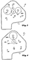
- FIG. 2A and 2B shows a gear 10 with a housing 11 which carries a plurality of rotatable shafts, gears, clutches and bearings.
- the shafts are aligned parallel to one another and are rotatably supported on two walls 12, 13 which are connected to one another in such a way that they form the housing 11.
- the input shaft S1 is rotatably mounted in the housing 11 and has an input end 14 that serves to introduce the torque.
- An input gear GF1 is rotatably connected to the input shaft S1.
- the fixed input gear GF1 is an integral part of the input shaft S1.
- the input shaft S1 also has a PTO shaft end 16, via which the PTO power is output. It can be used in a known manner to deliver power to various attachments or accessories that are used together and in connection with the work vehicle, for example a tractor.
- the auxiliary shafts S2, S3, S4 and S5, the output shaft S6 and the auxiliary shaft S7 are rotatably supported in the housing 11.
- Corresponding fixed gears GF2, GF3, GF4, GF5, GF6 and GF7 are arranged in a rotationally fixed manner on these shafts S2, S3, S4, S5, S6 and S7, for example by welding.
- the gears GR1, GR2, GRR and GRA are rotatably mounted on their associated shafts S4, S2, S3 and S2 and can be set relative to them by means of associated clutches C1, C2, CR and CA.
- the gears GRBA and GRBB are rotatably mounted on their associated shaft S3 and can be optionally set relative to this by means of an associated clutch CB.
- the rotatable gearwheels GRBA and GRBB are preferably designed as double gearwheels, as is shown in FIG. 2.
- the gears GRC, GRL, GRM and GRH are rotatably supported on their associated shafts S4, S5, S7 and S6 and can be select from these using associated CC, CL, CM and CH couplings.
- the output shaft S6 has an output end 18 through which the output power is output.
- the input shaft S1 is arranged approximately in the middle of the approximately circular or arc-shaped secondary and output shafts S2, S3, S4, S5, S6 and S7, the sequence of the secondary and Output shafts are in the order of their counterclockwise order if starting with S2.
- the input gear GF1 meshes with the rotatable gear wheels GR1, GR2 and GRR, which form an input set of the rotatable gear wheels.
- the clutches C1, C2 and CR can optionally fix one of the rotatable gear wheels GR1, GR2, GRR of the input set on the associated shaft S4, S2 or S3 in order to have one of the input gear GF1 receive speed derived from the input power and transmit a resultant of this speed to selected gear combinations of the gears GF2, GF3, GF4, GF5, GF6, GF7, GRA, GRBA, GRBB, GRC, GRL, GRM and GRH, in order to choose from a number of Select gears to select any gear to deliver to output end 18 of output shaft S6.
- the gear combinations are different, depending on the gears that are actually connected to the drive or drive.
- the gears are connected to the drive.
- a drive connection can include the direct tooth engagement between gear wheels which are fixed on their shaft or which are rotatably mounted on the shaft, one or more of the clutches associated with them being actuated or not actuated.
- the drive connection can comprise one or more gearwheels fixed on the same shaft or gearwheels rotatably mounted on the same shaft when their corresponding couplings are activated.
- the transmission 10 is divided into a gear or change gear section and a group gear section.
- the shafts S2, S3, S4, the gears GF2, GF3, GF4, GR1, GR2, GRR, GRA, GRBA, GRBB, GRC and the clutches C1, C2, CR, CA, CB, CC form the change gear section.
- the shafts S5, S6, S7, the gears GF5, GF6, GF7, GRL, GRM, GRH and the clutches CL, CM, CH form the group transmission section.
- the change gear section receives the transmission input speed using the clutches C1, C2, CR to selectively select one of their associated rotatable gears GR1, GR2, GRR of the input set with the associated shaft S4 , S2, S3 to rotate.
- one of clutches C1, C2, CR is activated to receive the transmission input speed derived from the input power
- one of the clutches CA, CB, CC is also activated to select a result of a set of alternate transmission results of the speed derived from the input power over one of the gears GRA, GRC to transfer to the group transmission section.
- the group transmission section receives the gearbox results of the speed derived from the input power by using one of the rotatable gears GRA, GRC to drive a selected group transmission combination of the gears GF5, GF6, GF7, GRL, GRM, GRH of the group transmission section and to provide the output power.
- activation of the clutch CL selects a lower speed range for the output power, so that the gear GF5, which is drivingly connected to the gear GRL, receives the change gear result from the gear GRC of the change gear part, as is shown in FIGS. 2, 5 and 7 emerges.
- the lower speed range which is selected by activating the clutch CL, includes the lowest gears for the output power.
- the upper speed range which is selected by activating the clutch CH, includes the highest gears for the output power.
- the middle speed range which is selected by activating the clutch CM, overlaps the lower and the upper speed range.
- the middle speed range includes at least one of the output power gears that is lower than at least one of the lower speed range gears and at least one other of the output power gears that is higher than at least one of the upper speed range gears.
- this overlap of the middle speed range with the lower and the upper speed range provides the operator with a large proportion of gears in the regular work area. Furthermore, the operator can switch between successive gears that occur in the different speed ranges without making a complete energy level change between the different ranges.
- the ratio combinations of the gears of the change gear section and the group gear section depend on the preselected meshing of the gears, the selective activation of the clutches and the preselected number of teeth of each of the gears.
- the input gear GF1 meshes with the rotatably mounted gear wheels GR1, GR2, GRR of the input set.
- the fixed gear GF3 meshes with the fixed gears GF2 and GF4.
- the gears GRBA, GRBB are designed as double gears, rotatably mounted together on the shaft S3 and by activating the clutch CB definable on shaft S3.
- the rotatable gear GRA meshes with the rotatable gear GRBB and the fixed gear GF7, which in turn meshes with the rotatable gear GRH.
- the fixed gear GF6 meshes with the rotatable gears GRL and GRM.
- the gear ratios obtained by meshing any pair of gears GF1, GF2, GF3, GF4, GF5, GF6, GF7, GR1, GR2, GRR, GRA, GRBA, GRBB, GRC, GRL, GRM, GRH depend on corresponding number of teeth.
- the toothed wheels shown in FIG. 2 have the number of teeth as shown in Table 1.
- the desired transmission output speeds can be obtained by optionally combining the gear ratios of pairs of gears GF1, GF2, GF3, GF4, GF5, GF6, GF7, GR1, GR2, GRR, GRA, GRBA that are connected to one another in the drive , GRBB, GRC, GRL, GRM, GRH.
- the gear ratios of the drive-connected gearwheels and the position of the double gearwheel, which is formed from the gearwheels GRBA and GRBB are depicted in accordance with the design considerations, which reflect the speeds preferred by the manufacturer, seller, customer and operator of the work vehicle.
- the clutches C1, C2, CR, CA, CB, CC, CL, CM, CH are optionally activated in accordance with Table 2 in order to connect the associated gearwheels to their associated shafts, resulting in the speed derived from the input power and is given as output power.
- Table 2 the values given in Table 2 are approximate values for kilometers per hour (approx. Km / h), which facilitate the understanding of the invention, but are only exemplary and vary according to the wheel size, the axle reduction ratio and others Have the characteristics of the work vehicle changed.
- transmission 10 provides eighteen forward gears and nine reverse gears using seventeen gears and nine clutches.
- six clutches C1, C2, CR, CA, CB, CC form the change gear section and three clutches CL, CM, CH form the group transmission section.
- the gear ratio for each gear corresponds to the speed of the input shaft S1 relative to the speed of the output shaft S6.
- a negative gear ratio indicates that the output shaft S6 rotates counter to the input shaft S1, and its value corresponds to that of one of the forward gears, as shown in Table 2.
- a positive gear ratio indicates that the output shaft S6 rotates in the same direction as the input shaft S1 and corresponds to one of the reverse gears. For example, assuming that the input shaft S1 always rotates clockwise, a clockwise rotation of the output shaft corresponds to a forward gear and a counterclockwise rotation corresponds to a reverse gear.
- the invention provides a large proportion of forward gears, namely forward gears F5, F6, F7, F8, F9, F10, F11, F12, F13, which are in the regular operating range of approximately 5 to 15 km / h lie. This is due to the overlap of the middle speed range with the lower and the upper speed range.
- the regular working range includes the forward gears F5, F7, F9 of the lower speed range, the forward gears F6, F8, F10, F12 of the medium speed range and the forward gears F11, F13 of the upper speed range.
- the forward gears F4, F6, F8 of the medium speed range are offset with the forward gears F5, F7, F9 of the lower speed range, that is to say they follow one another in an alternating sequence.
- the forward gears F12, F14 of the middle speed range are offset with the forward gears F11, F13 of the upper speed range. Therefore, the operator of the work vehicle can switch between the ranges of the forward gears without having to go through a complete change in energy levels between the various ranges. For example, the operator can switch directly from forward gear F3 of the lower speed range to forward gear F4 of the medium speed range without first having to perform a complete conversion between the energy levels of the lower and medium speed ranges.
- the speed of the rotating components is controlled by actuating the clutches. Furthermore, the difference between the speeds of the rotating components determines the energy level change that occurs during a switchover between the forward or reverse gears.
- actuation of the clutches C1, CB, CL determines the speed of the rotating components for the forward gear F3 of the lower speed range.
- actuation of the clutches C1, CA, CM determines the speed of the rotating components for the forward gear F4 of the medium speed range.
- a group changeover between the forward gears F3 and F4 leads to a small change in the energy level of the rotating components because the lower and the middle speed range overlap.
- group shifts in the transmission 10 between successive gears result in a small energy level change on the rotating shafts, gears, clutches and bearings because the lower, the middle and the upper speed range overlap.
- the work vehicle experiences a softer range switchover by making a smaller change in energy level on the rotating components. Therefore, the range switching between gears F3 and F4 is smooth. The range switching between other successive gears from different ranges is also soft. In addition, a reduction in the energy level change in group switching leads to a reduction in the switching times required.
- reverse gear R3 of the medium speed range is offset with reverse gear R4 of the lower speed range.
- reverse gear R7 of the middle speed range is offset with the reverse gear R6 of the upper speed range. Similar to the group shifts between successive forward gears as described above, the operator can perform a group shift between successive reverse gears without having to make a complete energy level change between the different groups.
- a translation sequence is formed by drivingly connecting a plurality of gears.
- the translation sequence is used in at least one of the translation combinations to provide a reduction or decrease in the speed transmitted to the translation sequence, and is used in at least one other translation combination to provide an increase in the speed transmitted to the translation sequence.
- the rotatable gears GRA, GRBB, GRBA, GRC are drivingly connected to form a gear ratio sequence which is alternatively traversed forwards or backwards in order to reduce or increase the speed desired for the gear ratio combination of the forward gears F1, F2, F12 , F14, F17, F18 and the reverse gears R1, R7, R9 to deliver, as is apparent from Figures 2 to 7 and Table 2.
- the rotatable gears GRA, GRBB, GRBA, GRC are drivingly connected to form a translation sequence which provides the desired reduction in the speed transmitted to this translation sequence for the translation combinations of the gears F1, F2, R1.
- the size of this transmission sequence based on the number of teeth of the rotatable gears GRA, GRBB, GRBA, GRC is preferably (70/42) (70/42) for the speed reduction, as can be seen from Table 1.
- the rotatable gears GRA, GRBB, GRBA, GRC are drivingly connected in the opposite direction, namely GRC, GRBA, GRBB, GRA, in order to form an opposite translation sequence.
- This translation sequence of the rotatable gears GRC, GRBA, GRBB, GRA is used to provide the desired increase in the speed transmitted to this translation sequence for the gear combinations of the gears F12, F14, F17, F18, R7, R9.
- the size of this transmission sequence based on the number of teeth of the rotatable gear wheels GRC, GRBA, GRBB, GRA is preferably (42/70) (42/70) for increasing the speed, as can be seen from Table 1.
- the number of gears can be used required to provide the gears for the output power can be reduced.
- less gear assembly material is required because fewer gears are used.
- fewer gears rotate in the transmission 10 so that less kinetic energy builds up and the energy change of the components during the shift is reduced.
- due to this decrease in the energy level change of the rotating shafts, gears, clutches and bearings there is less time required for group shifts and an increase in the softness of these shifts.
- the double use of the rotating gears GRA, GRBB, GRBA, GRC not only results in the reduction of the total number of required gears, but also allows the rotatable bearing of the shafts S1, S2, S3, S4, S5, S6, S7, the all gears of the transmission 10 carry, in the two opposite walls 12, 13, which are joined together to form the housing 11.
- the shafts S1, S2, S3, S4, S5, S6, S7 in the gear 10 within the channel or the volume that is through the walls 12, 13 is formed are aligned parallel to each other. Therefore, the double use of the rotating gears GRA, GRBB, GRBA, GRC increases the compactness of the transmission 10 and reduces the space required for the transmission 10 in a work vehicle.
- the group transmission section can be arranged by means of a corresponding arrangement of the shafts, gear wheels and couplings be upstream of the change gear section so that the group transmission section receives the input power, the change gear section receives the result of the input power provided by the group transmission section and the change gear section outputs the output power.
- at least one gear of the upper speed range of the output power can alternate with at least one gear of the lower speed range of the output power.
- the interleaving (alternation) of the middle speed range of the output power with the upper or lower speed range of the output power can include any interference selection for the gears with different degrees of conformity and different symmetry.
- the gear ratios can be preselected so that each of the lower, middle and upper speed ranges can be selected by activating one of the clutches CL, CM, CH. You can also vary both the preselected ratios of the drivingly connected gears and the position of the double gear, which is formed by the gears GRBA, GRBB.
Landscapes
- Engineering & Computer Science (AREA)
- General Engineering & Computer Science (AREA)
- Mechanical Engineering (AREA)
- Structure Of Transmissions (AREA)
Priority Applications (1)
| Application Number | Priority Date | Filing Date | Title |
|---|---|---|---|
| EP99121622A EP0971156B1 (fr) | 1995-03-07 | 1996-03-02 | Transmission à arbres intermédiaires |
Applications Claiming Priority (2)
| Application Number | Priority Date | Filing Date | Title |
|---|---|---|---|
| US399782 | 1995-03-07 | ||
| US08/399,782 US5557978A (en) | 1995-03-07 | 1995-03-07 | Countershaft power transmission |
Related Child Applications (1)
| Application Number | Title | Priority Date | Filing Date |
|---|---|---|---|
| EP99121622A Division EP0971156B1 (fr) | 1995-03-07 | 1996-03-02 | Transmission à arbres intermédiaires |
Publications (3)
| Publication Number | Publication Date |
|---|---|
| EP0731290A2 true EP0731290A2 (fr) | 1996-09-11 |
| EP0731290A3 EP0731290A3 (fr) | 1997-12-10 |
| EP0731290B1 EP0731290B1 (fr) | 2000-05-31 |
Family
ID=23580944
Family Applications (2)
| Application Number | Title | Priority Date | Filing Date |
|---|---|---|---|
| EP99121622A Expired - Lifetime EP0971156B1 (fr) | 1995-03-07 | 1996-03-02 | Transmission à arbres intermédiaires |
| EP96103271A Expired - Lifetime EP0731290B1 (fr) | 1995-03-07 | 1996-03-02 | Transmission à arbres intermédiaires |
Family Applications Before (1)
| Application Number | Title | Priority Date | Filing Date |
|---|---|---|---|
| EP99121622A Expired - Lifetime EP0971156B1 (fr) | 1995-03-07 | 1996-03-02 | Transmission à arbres intermédiaires |
Country Status (6)
| Country | Link |
|---|---|
| US (1) | US5557978A (fr) |
| EP (2) | EP0971156B1 (fr) |
| JP (1) | JP3935226B2 (fr) |
| BR (1) | BR9600935A (fr) |
| CA (1) | CA2168816C (fr) |
| DE (2) | DE59610723D1 (fr) |
Families Citing this family (13)
| Publication number | Priority date | Publication date | Assignee | Title |
|---|---|---|---|---|
| DE4416929A1 (de) * | 1994-05-13 | 1995-11-16 | Zahnradfabrik Friedrichshafen | Unter Last schaltbares, mehrgängiges Wendegetriebe |
| US5722291A (en) * | 1996-08-26 | 1998-03-03 | New Venture Gear, Inc. | Manual transmission with synchronized reverse gear |
| KR100503612B1 (ko) * | 1998-08-28 | 2006-08-30 | 두산인프라코어 주식회사 | 중장비용 변속기 |
| US6085606A (en) * | 1998-11-03 | 2000-07-11 | Eaton Corporation | Mechanical transmission with reduced ratio steps in upper transmission ratios |
| DE10131329A1 (de) * | 2001-06-28 | 2003-01-09 | Zahnradfabrik Friedrichshafen | Lastschaltbares Wendegetriebe |
| US7191676B2 (en) * | 2002-09-23 | 2007-03-20 | Vladimir Abramov | Universal multifarious gearbox of mutually definite units and method therefore |
| US8011274B2 (en) * | 2006-08-28 | 2011-09-06 | Vladimir Abramov | Gear box apparatus |
| JP5064270B2 (ja) * | 2008-03-14 | 2012-10-31 | 株式会社岡村製作所 | モータ駆動式産業用車両 |
| US9062761B2 (en) | 2013-10-17 | 2015-06-23 | Deere & Company | Torque-based shifting |
| CN110516384B (zh) * | 2019-08-30 | 2022-09-13 | 西北工业大学 | 一种多输入多输出齿轮传动系统动力学建模方法 |
| WO2021173414A1 (fr) | 2020-02-25 | 2021-09-02 | Allison Transmission, Inc. | Transmission planétaire à vitesses multiples |
| US12007005B2 (en) | 2020-03-09 | 2024-06-11 | Allison Transmission, Inc. | Multi-speed planetary transmission |
| US12612954B2 (en) | 2024-07-18 | 2026-04-28 | Allison Transmission, Inc. | Multi-speed planetary transmission |
Family Cites Families (11)
| Publication number | Priority date | Publication date | Assignee | Title |
|---|---|---|---|---|
| US4658662A (en) * | 1984-04-16 | 1987-04-21 | Rundle Kenneth P | Transmission and PTO system for tractors and utility cycles |
| US4823639A (en) * | 1984-06-04 | 1989-04-25 | Caterpillar Inc. | Countershaft transmission |
| US4726246A (en) * | 1986-10-01 | 1988-02-23 | Caterpillar Inc. | Countershaft transmission having two forward and two reverse speeds |
| US4788889A (en) * | 1987-03-19 | 1988-12-06 | Eaton Corporation | Mechanical transmission and control method therefor |
| US4846009A (en) * | 1987-10-21 | 1989-07-11 | Caterpillar Inc. | Countershaft transmission |
| US5063793A (en) * | 1990-09-06 | 1991-11-12 | Deere & Company | Speed forward, 12 speed reverse powershift transmission |
| US5249475A (en) * | 1992-08-31 | 1993-10-05 | Deere & Company | Eight- to sixteen-speed powershift transmission |
| US5337624A (en) * | 1992-12-08 | 1994-08-16 | Ford New Holland, Inc. | Powershift transmission with overlapping ranges of ratios |
| US5421222A (en) * | 1993-05-14 | 1995-06-06 | Eaton Corporation | Compound transmission having auto range actuation through dual entry first speed gear |
| US5465630A (en) * | 1993-09-14 | 1995-11-14 | Kubota Corporation | Drive transmitting apparatus for a working vehicle |
| US5471892A (en) * | 1994-04-21 | 1995-12-05 | General Motors Corporation | Multi-speed parallel axis three countershafts and an output shaft power transmission |
-
1995
- 1995-03-07 US US08/399,782 patent/US5557978A/en not_active Expired - Lifetime
-
1996
- 1996-02-05 CA CA002168816A patent/CA2168816C/fr not_active Expired - Fee Related
- 1996-03-02 EP EP99121622A patent/EP0971156B1/fr not_active Expired - Lifetime
- 1996-03-02 EP EP96103271A patent/EP0731290B1/fr not_active Expired - Lifetime
- 1996-03-02 DE DE59610723T patent/DE59610723D1/de not_active Expired - Lifetime
- 1996-03-02 DE DE59605332T patent/DE59605332D1/de not_active Expired - Lifetime
- 1996-03-06 BR BR9600935A patent/BR9600935A/pt not_active IP Right Cessation
- 1996-03-07 JP JP05058496A patent/JP3935226B2/ja not_active Expired - Fee Related
Also Published As
| Publication number | Publication date |
|---|---|
| JPH08296705A (ja) | 1996-11-12 |
| CA2168816A1 (fr) | 1996-09-08 |
| EP0731290B1 (fr) | 2000-05-31 |
| EP0971156B1 (fr) | 2003-09-17 |
| BR9600935A (pt) | 1997-12-30 |
| DE59610723D1 (de) | 2003-10-23 |
| JP3935226B2 (ja) | 2007-06-20 |
| DE59605332D1 (de) | 2000-07-06 |
| EP0971156A2 (fr) | 2000-01-12 |
| EP0731290A3 (fr) | 1997-12-10 |
| US5557978A (en) | 1996-09-24 |
| CA2168816C (fr) | 1999-07-06 |
| EP0971156A3 (fr) | 2000-07-19 |
Similar Documents
| Publication | Publication Date | Title |
|---|---|---|
| DE2514781C3 (de) | Zahnräderwechselgetriebe in Gruppenbauart, insbesondere für land- und/oder bauwirtschaftlich nutzbare Kraftfahrzeuge | |
| EP0474143B1 (fr) | Transmission | |
| DE2447581A1 (de) | Planetenrad-wechselgetriebe, insbesondere fuer kraftfahrzeuge | |
| DE102011076391A1 (de) | Parallelschaltgetriebe | |
| DE3507600A1 (de) | Planetengetriebe | |
| EP0516010B1 (fr) | Transmission | |
| EP0731290B1 (fr) | Transmission à arbres intermédiaires | |
| DE102011056517A1 (de) | Getriebe für ein Kraftfahrzeug und Verfahren zum Steuern eines solchen Getriebes | |
| EP2914874A1 (fr) | Boîte de vitesses à double embrayage | |
| EP2715185A1 (fr) | Boîte de vitesse parallèle d'un véhicule automobile | |
| DE2916738A1 (de) | Schaltgetriebe mit zusatzgetriebe | |
| EP0552673B1 (fr) | Boîte de vitesse pour véhicule à moteur | |
| EP2655924B1 (fr) | Transmission à contournement à double embrayage | |
| DE102019207925A1 (de) | Nebenabtriebsgetriebe und landwirtschaftliche Arbeitsmaschine | |
| EP0397804B1 (fr) | Boite de vitesses couplable sous charge a rapport variable en continu | |
| DE102011076381A1 (de) | Doppelkupplungsgetriebe | |
| EP4098908B1 (fr) | Engrenage prise de force et véhicule utilitaire agricole | |
| EP0624739B1 (fr) | Transmission à arbre intermédiaire | |
| DE10335074A1 (de) | Mehrganggetriebe | |
| DE112011105576B4 (de) | Mehrkupplungsgetriebe für ein Kraftfahrzeug | |
| EP0105124A1 (fr) | Boîte de vitesses à construction en groupes | |
| DE10137356A1 (de) | Fahrzeuggetriebe | |
| EP3739238A1 (fr) | Transmission de puissance pour les machines agricoles | |
| DE102021211663B3 (de) | Landmaschinengetriebe, insbesondere für einen Ackerschlepper | |
| DE102011089154B4 (de) | Doppelkupplungsgetriebe |
Legal Events
| Date | Code | Title | Description |
|---|---|---|---|
| PUAI | Public reference made under article 153(3) epc to a published international application that has entered the european phase |
Free format text: ORIGINAL CODE: 0009012 |
|
| AK | Designated contracting states |
Kind code of ref document: A2 Designated state(s): DE FR GB IT |
|
| PUAL | Search report despatched |
Free format text: ORIGINAL CODE: 0009013 |
|
| AK | Designated contracting states |
Kind code of ref document: A3 Designated state(s): DE FR GB IT |
|
| 17P | Request for examination filed |
Effective date: 19980115 |
|
| 17Q | First examination report despatched |
Effective date: 19990401 |
|
| GRAG | Despatch of communication of intention to grant |
Free format text: ORIGINAL CODE: EPIDOS AGRA |
|
| GRAG | Despatch of communication of intention to grant |
Free format text: ORIGINAL CODE: EPIDOS AGRA |
|
| GRAH | Despatch of communication of intention to grant a patent |
Free format text: ORIGINAL CODE: EPIDOS IGRA |
|
| RAP1 | Party data changed (applicant data changed or rights of an application transferred) |
Owner name: DEERE & COMPANY |
|
| GRAH | Despatch of communication of intention to grant a patent |
Free format text: ORIGINAL CODE: EPIDOS IGRA |
|
| GRAA | (expected) grant |
Free format text: ORIGINAL CODE: 0009210 |
|
| AK | Designated contracting states |
Kind code of ref document: B1 Designated state(s): DE FR GB IT |
|
| REF | Corresponds to: |
Ref document number: 59605332 Country of ref document: DE Date of ref document: 20000706 |
|
| GBT | Gb: translation of ep patent filed (gb section 77(6)(a)/1977) |
Effective date: 20000630 |
|
| ET | Fr: translation filed | ||
| ITF | It: translation for a ep patent filed | ||
| PLBE | No opposition filed within time limit |
Free format text: ORIGINAL CODE: 0009261 |
|
| STAA | Information on the status of an ep patent application or granted ep patent |
Free format text: STATUS: NO OPPOSITION FILED WITHIN TIME LIMIT |
|
| 26N | No opposition filed | ||
| REG | Reference to a national code |
Ref country code: GB Ref legal event code: IF02 |
|
| PGFP | Annual fee paid to national office [announced via postgrant information from national office to epo] |
Ref country code: IT Payment date: 20140324 Year of fee payment: 19 Ref country code: FR Payment date: 20140317 Year of fee payment: 19 |
|
| PGFP | Annual fee paid to national office [announced via postgrant information from national office to epo] |
Ref country code: GB Payment date: 20140327 Year of fee payment: 19 |
|
| PGFP | Annual fee paid to national office [announced via postgrant information from national office to epo] |
Ref country code: DE Payment date: 20150331 Year of fee payment: 20 |
|
| GBPC | Gb: european patent ceased through non-payment of renewal fee |
Effective date: 20150302 |
|
| PG25 | Lapsed in a contracting state [announced via postgrant information from national office to epo] |
Ref country code: IT Free format text: LAPSE BECAUSE OF NON-PAYMENT OF DUE FEES Effective date: 20150302 |
|
| REG | Reference to a national code |
Ref country code: FR Ref legal event code: ST Effective date: 20151130 |
|
| PG25 | Lapsed in a contracting state [announced via postgrant information from national office to epo] |
Ref country code: GB Free format text: LAPSE BECAUSE OF NON-PAYMENT OF DUE FEES Effective date: 20150302 |
|
| PG25 | Lapsed in a contracting state [announced via postgrant information from national office to epo] |
Ref country code: FR Free format text: LAPSE BECAUSE OF NON-PAYMENT OF DUE FEES Effective date: 20150331 |
|
| REG | Reference to a national code |
Ref country code: DE Ref legal event code: R071 Ref document number: 59605332 Country of ref document: DE |