EP0731421B1 - Informationsaufzeichnungsverfahren und Informationswiedergabeverfahren - Google Patents
Informationsaufzeichnungsverfahren und Informationswiedergabeverfahren Download PDFInfo
- Publication number
- EP0731421B1 EP0731421B1 EP96103455A EP96103455A EP0731421B1 EP 0731421 B1 EP0731421 B1 EP 0731421B1 EP 96103455 A EP96103455 A EP 96103455A EP 96103455 A EP96103455 A EP 96103455A EP 0731421 B1 EP0731421 B1 EP 0731421B1
- Authority
- EP
- European Patent Office
- Prior art keywords
- recording
- information
- data
- frames
- recording medium
- Prior art date
- Legal status (The legal status is an assumption and is not a legal conclusion. Google has not performed a legal analysis and makes no representation as to the accuracy of the status listed.)
- Expired - Lifetime
Links
- 238000000034 method Methods 0.000 title claims description 30
- 230000003287 optical effect Effects 0.000 claims description 48
- 238000010586 diagram Methods 0.000 description 5
- 230000007547 defect Effects 0.000 description 4
- 239000000428 dust Substances 0.000 description 2
- 230000006870 function Effects 0.000 description 2
- 238000004519 manufacturing process Methods 0.000 description 2
- 231100000241 scar Toxicity 0.000 description 2
- 230000000694 effects Effects 0.000 description 1
- 238000000605 extraction Methods 0.000 description 1
- 230000009191 jumping Effects 0.000 description 1
- 239000011159 matrix material Substances 0.000 description 1
- 238000012986 modification Methods 0.000 description 1
- 230000004048 modification Effects 0.000 description 1
Images



Classifications
-
- G—PHYSICS
- G11—INFORMATION STORAGE
- G11B—INFORMATION STORAGE BASED ON RELATIVE MOVEMENT BETWEEN RECORD CARRIER AND TRANSDUCER
- G11B20/00—Signal processing not specific to the method of recording or reproducing; Circuits therefor
- G11B20/10—Digital recording or reproducing
- G11B20/18—Error detection or correction; Testing, e.g. of drop-outs
-
- G—PHYSICS
- G11—INFORMATION STORAGE
- G11B—INFORMATION STORAGE BASED ON RELATIVE MOVEMENT BETWEEN RECORD CARRIER AND TRANSDUCER
- G11B7/00—Recording or reproducing by optical means, e.g. recording using a thermal beam of optical radiation by modifying optical properties or the physical structure, reproducing using an optical beam at lower power by sensing optical properties; Record carriers therefor
- G11B7/002—Recording, reproducing or erasing systems characterised by the shape or form of the carrier
- G11B7/0033—Recording, reproducing or erasing systems characterised by the shape or form of the carrier with cards or other card-like flat carriers, e.g. flat sheets of optical film
-
- G—PHYSICS
- G11—INFORMATION STORAGE
- G11B—INFORMATION STORAGE BASED ON RELATIVE MOVEMENT BETWEEN RECORD CARRIER AND TRANSDUCER
- G11B27/00—Editing; Indexing; Addressing; Timing or synchronising; Monitoring; Measuring tape travel
- G11B27/10—Indexing; Addressing; Timing or synchronising; Measuring tape travel
- G11B27/19—Indexing; Addressing; Timing or synchronising; Measuring tape travel by using information detectable on the record carrier
- G11B27/28—Indexing; Addressing; Timing or synchronising; Measuring tape travel by using information detectable on the record carrier by using information signals recorded by the same method as the main recording
- G11B27/30—Indexing; Addressing; Timing or synchronising; Measuring tape travel by using information detectable on the record carrier by using information signals recorded by the same method as the main recording on the same track as the main recording
- G11B27/3027—Indexing; Addressing; Timing or synchronising; Measuring tape travel by using information detectable on the record carrier by using information signals recorded by the same method as the main recording on the same track as the main recording used signal is digitally coded
-
- G—PHYSICS
- G11—INFORMATION STORAGE
- G11B—INFORMATION STORAGE BASED ON RELATIVE MOVEMENT BETWEEN RECORD CARRIER AND TRANSDUCER
- G11B7/00—Recording or reproducing by optical means, e.g. recording using a thermal beam of optical radiation by modifying optical properties or the physical structure, reproducing using an optical beam at lower power by sensing optical properties; Record carriers therefor
- G11B7/007—Arrangement of the information on the record carrier, e.g. form of tracks, actual track shape, e.g. wobbled, or cross-section, e.g. v-shaped; Sequential information structures, e.g. sectoring or header formats within a track
- G11B7/00745—Sectoring or header formats within a track
Definitions
- the present invention relates generally to methods of recording and reproducing information onto and from such pre-formatted information recording media. More particularly, the present invention is concerned with a technique which is applicable to optical information recording media to improve the data storing efficiency, recording accuracy and burst-error correcting capability of the media.
- an optical card is used as a recording medium
- a plurality of information units (sectors) are usually recorded onto a data track. But, as the number of sectors on the data track is increased, the length of the individual sectors would become shorter and the number of interleaves (i.e., the amount of information that can be mixedly contained within each sector) would decrease. This results in reduced scattering of the recorded data and hence in reduced error correction capability.
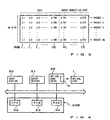
- an 48-bit frame is created which comprises an 8-bit synchronization signal F and 40 first-bit data of the individual packets and is serially arranged in the order of "F, a1, b1, c1, ...n1".
- another 48-bit frame is created which comprises an 8-bit synchronization signal F and 40 second-bit data of the individual packets and is serially arranged in the order of "F, a2, b2, c2, ...n2”
- another 48-bit frame is created which comprises an 8-bit synchronization signal F and 40 third-bit data of the individual packets and is serially arranged in the order of "F, a3, b3, c3, ...n3", and so on.
- a total of 272 frames are created and serially connected to ultimately form a data train of 13,056 (48 ⁇ 272) bits, which is recorded onto a single data track of the optical card.
- a similar lead-in section is also pre-formatted at the rear end of the track. That is, the lead-in sections are pre-recorded or pre-formatted on both sides of the data recording area of each track, with the BOS section being interposed between one of the lead-in sections and recording area.
- the known optical card format has the BOS section pre-formatted next to only one end portion thereof, data can be recorded only when the optical card is moved relative to the head just in one particular direction although the optical card reciprocates in two directions, and this results in poor efficiency.
- the information recorded on the BOS section can not be read due to some defect such as dust, stain or scar on or in the optical card surface, desired data recording can not be effected at all.
- EP-A-0277 655 shows a card-forming recording medium having a plurality of recording tracks wherein a data record starting flag or a data record end flag is provided on the recording track.
- the flags can be used to indicate the data recording direction so that the extraction of the recorded data is possible in each direction.
- EP-A-0269 387 shows an optical record medium having a number of data tracks and a number of control tracks. After a data signal has been recorded in a data track, a mark is recorded in the control data track so that it is possible to know how many data tracks have been already used. Neither EP-A-0277 655 nor EP-A-0269 387 show pre-formatted synchronization signals so that undesirable jitters in the reproduced signals can occur as already said above.
- EP 0409 649 A2 discloses an information recording and reproducing device wherein the recording medium is a magnetooptical disk that includes a pre-format section for each of a plurality of tracks, a sector mark section intended for sector-by-sector synchronization, and an information section. A plurality of marks are pre-recorded in the pre-format section. There are no header sections on each track.
- the method for recording information according to the invention is defined by claim 1, and to the method for reproducing information is defined by claim 2.
- Fig. 1 is a schematic plan view showing an optical card 1 of an optical information recording medium .
- a rectangular information recording region 2 which occupies about 60% of the total area of the surface.
- the information recording region 2 includes a central write-once data recording section 3 and two pre-formatted or pre-recorded header sections 4a and 4b located at both ends of the data recording section 3.
- the information recording region 2 has a plurality of information recording tracks extending in "x" direction in the figure and arranged in parallel to each other in "y” direction.
- the "x" direction is where a recording/reproducing head H (Fig.
- one end (left side in Fig. 1) of the optical card 1 where the header section 4a is provided will be referred to as a fore end, while the other end (right side in Fig. 1) of the optical card 1 where the header section 4b is provided will be referred to as a rear end.
- a plurality of servo- tracking guide tracks are also provided on the recording region 2, each interposed between adjacent information recording tracks, as well known in the art.
- Each of the information recording tracks 21 includes a central write-once data recording area 31, and fore and rear header sections 4a1 and 4b1 located on opposite sides of the data recording track section 31.
- Such data recording area 31 and fore and rear header sections 4a1 and 4b1 of the individual recording tracks 21 together constitute the data recording section 3 and fore and rear header sections 4a and 4b of Fig. 1, respectively.
- the fore header section 4a1 of each information recording track 21 is composed of a lead-in section 42a having a group of predetermined data pre-formatted for the purpose of bit synchronization, and a BOS (Beginning of Sector) section 43a having address information identifying that recording track 21.
- the lead-in section 42a is located adjacent to the extreme fore end of the recording track 21, and the BOS section 43a is located to the right of the lead-in section 42a, i.e., closer to the middle of the recording track 21.
- This arrangement is for the purpose of allowing the lead-in section 42a to be first read by the head H when the relative movement of the head H is in the backward (i.e., fore-to-rear) "x" direction.
- An 8-bit extreme-end frame synchronization signal F is added, at the extreme read end of the lead-in section 42b of the rear header section 4b1, so as to be first read by the head H when the relative movement of the head is in the forward (i.e., rear-to-fore) "x" direction.
- the track section 31 is comprised of storing areas for a plurality of frames, say, 272 frames, and each of the frames has a predetermined data size such as 48 bits.
- a predetermined frame synchronizing signal F In each of the frame storing areas is pre-formatted a predetermined frame synchronizing signal F, so that information is non-rewritably recorded onto a desired frame storing area by referring to the pre-formatted synchronization signal F.
- one frame may have a size of 48 bits so that the synchronization signal F pre-formatted in the area has a size of 8 bits and the remaining 40 bits form an available data recording segment D.
- a total of 272 frame synchronization signals F are pre-formatted at constant intervals in predetermined locations of the data recording area 31, with the data recording segment D for each frame being left blank for the user's subsequent writing.
- pre-formatting is used to mean pre-recording predetermined information such as bit synchronization signal S, frame synchronization signal F and header information A such as address information in accordance with predetermined standards at the time of fabrication of the optical card 1. Recording such pre-format information may be effected by use of any conventionally-known recording apparatus and method or technique, and hence will not be described here any further.
- Fig. 5 is a flowchart of a program, to be executed by the CPU 52, for recording information onto the optical card 1 set in the optical card drive 55.
- the recording/reproducing head H which is provided in association with the optical card drive 55 is caused to access the selected recording track 21.
- the head H is moving relative to the track 21, it is possible to ascertain whether or not the recording/reproducing head H is actually accessing the selected recording track 21, by referring to the header information A including the track address information pre-formatted in the BOS section of the header section 4a1 or 4b1. Because the two BOS sections 43a and 43b are provided at the opposite ends of the track 21, one of the sections 43a and 43b can always be referred to and hence recording of the information can be effected, irrespective of the direction of the relative oscillating movement of the recording/reproducing head (the forward or backward "x" direction) to the optical card 1.
- the optical card drive 55 continues the forward or backward relative movement of the recording/reproducing head H along the track 21, during which time it performs the following recording process on the optical card 1.
- step S4 the data of the individual frames are read out from the data map (Fig. 3) stored in the recording/reproducing buffer memory and are sequentially recorded onto the corresponding recording areas D (Fig. 2) in an interleave fashion. More specifically, when the relative movement of the recording/reproducing head H is in the backward "x" direction arrowed in Fig. 2, 40-bit data comprising respective first bit data of packets 1 - 40 arranged in the order of "a1, b1, c1, ... n1" are read out in a serial manner and stored into the recording segment D corresponding to frame 1. Next, 40-bit data comprising respective second bit data of packets 1 - 40 arranged in the order of "a2, b2, c2, ...
- the data map is read in the opposite direction to the above-mentioned, i.e., in the order of n272, ... b272, a272 and n1, ... c1, b1, a1, so that all the data can be recorded in the same direction.
- the data map may be read in the above-mentioned direction so that the data recorded direction varies among the recording tracks 21.
- a flag indicative of the direction of the recorded data may be recorded in the header sections 4a1 and 4b1 for each recording track 21 so that the data can be rearranged with reference to the flag during reproduction.
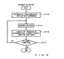
- the CPU 52 designates one or more tracks 21 from which to reproduce the recorded data.
- the recording/reproducing head H of the optical card drive 55 is caused to access the designated track 21.
- the header information A containing the track address information pre-formatted in the BOS section 43a or 43b of the header section 4a1 or 4b1 as the head H is moving relative to the track 21.
- the two BOS sections 43a and 43b are provided at the opposite ends of the track 21, one of the sections 43a and 43b can always be referred to and hence reproduction of the information can be effected, irrespective of the direction of the relative movement of the recording/reproducing head H. Even with the conventional optical cards having only one BOS section, the recording/reproducing head H is allowed to move relative to the card in either of the directions at the time of reproduction because no particular inconvenience would not arise from confirming the track address after reading out the recorded data on the track 21. However, if the BOS sections are provided at the opposite ends of the card as in the present invention, improper access to a wrong track 21 can be readily detected to immediately stop the reproducing operation on the track 21, which will significantly improve the reproducing efficiency.
- the optical card drive 55 continues the forward or backward relative movement of the recording/reproducing head H along the track 21, during which time it performs the following reproduction process.
- step S12 the data reproduced for each frame from the designated track 21 are temporarily stored into the above-mentioned recording/reproducing buffer memory. Then, the data for each packet are read out from the buffer memory after the data has been released from the interleaved state, and the reproduced packet data (190 bits) are checked and corrected for any possible error by use of the error correction codes (82 bits).
- step S13 it is examined whether the data on all the designated tracks 21 have been reproduced. If not, i.e., if there is another track 21 to be reproduced, the CPU 52 loops back to step S11 to repeat the above-mentioned operations for the unreproduced track.
- the reproduction is performed on the data of the individual frames which are, as mentioned earlier, recorded on accurate storing locations on the basis of the respective frame synchronization signals irrespective of whether the relative movement speed of the recording/reproducing head is uniform or not, it is possible to acquire good-quality reproduced signals with no jitters.
- the present invention can correct error easily without being influenced by any defect of the data recording areas such as dust, stain or scar.
- the present invention may be applied to any other write-once information recording media than the optical card, such as an optical disk where one circular track comprises a plurality of sectors and each of the sectors is an unit to be accessed.
- each sector may be considered as one information recording track of the present invention.
- the pre-formatting of two header sections at the opposite ends of each track in the present invention which allows the relative movement of the recording/reproducing head to be in either of the forward and backward "x" directions, may not have to be applied to the rotary recording media rotatable only in a single direction.
- the pre-formatting of frame-by-frame synchronization signals may be applied to the single-direction rotary recording media.
- the present invention may of course be applied to two-surface-recording optical cards as well as to single-surface-recording optical cards. It should be apparent that the present invention is also applicable to hybrid-type information recording media which for example have a function of an optical card and a function of another recording medium such as an IC or magnetic card.
- the present invention is characterized by predetermined synchronization signals pre-formatted in the storing areas for the individual frames in such a manner that information can be recorded on the storing area for a given frame by referring to the pre-formatted synchronization signal.
Landscapes
- Engineering & Computer Science (AREA)
- Signal Processing (AREA)
- Signal Processing For Digital Recording And Reproducing (AREA)
- Optical Recording Or Reproduction (AREA)
- Indexing, Searching, Synchronizing, And The Amount Of Synchronization Travel Of Record Carriers (AREA)
Claims (5)
- Verfahren zum Aufzeichnen von Informationen auf ein Informationsaufzeichnungsmedium, wobei das Aufzeichnungsmedium (1) mehrere Informationsaufzeichnungsspuren (21) und zwei Kopfabschnitte (4a1,4b1) aufweist, die an den vorderen und hinteren Enden jeder der Aufzeichnungsspuren (21) vorformatiert sind, wobei jede Aufzeichnungsspur mehrere Speicherbereiche (D) für mehrere Frames, die jeweils einer vorbestimmten Datengröße entsprechen, und ein Synchronisiersignal (F) einer vorbestimmten Datengröße, das auf dem Aufzeichnungsmedium in dem Speicherbereich (D) für jeden der Frames vorformatiert ist, aufweist, wobei das Verfahren folgende Schritte umfasst:dadurch gekennzeichnet, dassZugreifen auf eine gewünschte Spur (21) an dem vorderen oder hinteren Ende durch Bezugnahme auf einen der Kopfabschnitte (4a1,4b1) des vorderen oder hinteren Endes;Bewegen eines Aufzeichnungskopfs (H) relativ zu dem Aufzeichnungsmedium (1) von dem vorderen oder hinteren Ende zum anderen Ende der gewünschten Spur, auf die zugegriffen worden ist; undAufzeichnen der Informationen in einen der Speicherbereiche für ausgewählte Frames durch Bezugnahme auf das vorformatierte Synchronisiersignal (F) während der Bewegung des Kopfs (H) relativ zu dem Aufzeichnungsmedium (1),
in dem Schritt des Aufzeichnens der Informationen Daten einer Folge von aufzuzeichnenden Informationen durch Überlappung derart über die Frames verschachtelt werden, dass einzelne Teile der Daten innerhalb jedes Frames vermischt aufgezeichnet werden. - Verfahren zum Wiedergeben von Informationen von einem Informationsaufzeichnungsmedium, wobei das Aufzeichnungsmedium (1) mehrere Informationsaufzeichnungsspuren (21) und zwei Kopfabschnitte (4a1,4b1) aufweist, die an den vorderen und hinteren Enden jeder der Aufzeichnungsspuren vorformatiert sind, wobei jede der Aufzeichnungsspuren (21) mehrere Speicherbereiche (D) für mehrere Frames und ein Synchronisiersignal (F) einer vorbestimmten Datengröße, das auf dem Aufzeichnungsmedium in dem Speicherbereich für jedes der Frames vorformatiert ist, aufweist, wobei das Verfahren folgende Schritte umfasst:dadurch gekennzeichnet, dassZugreifen auf eine gewünschte Spur (21) an dem vorderen oder hinteren Ende durch Bezugnahme auf einen der Kopfabschnitte (4a1,4b1) des vorderen oder hinteren Endes;Bewegen eines Wiedergabekopfs (H) relativ zu dem Aufzeichnungsmedium (1) von dem vorderen oder hinteren Ende zum anderen Ende der gewünschten Spur, auf die zugegriffen worden ist; undWiedergeben der Informationen aus einem der Speicherbereiche (D) für ausgewählte Frames durch Bezugnahme auf das vorformatierte Synchronisiersignal (F) während der Bewegung des Kopfs (H) relativ zu dem Aufzeichnungsmedium (1),
Daten einer Folge von aufzuzeichnenden Informationen durch Überlappung derart über die Frames verschachtelt werden, dass einzelne Teile der Daten innerhalb jedes Frames vermischt aufgezeichnet werden,
und der Schritt des Wiedergebens der Informationen einen ersten Schritt zum Wiedergeben von Daten für jeden der Frames und einen zweiten Schritt zum Wiedergeben der Folgen von Informationen durch Auslösen der Informationen aus dem Verschachtelungszustand auf der Basis der wiedergegebenen Daten der einzelnen Frames umfasst. - Verfahren nach Anspruch 1 oder 2, bei dem die Folge von Informationen eine Datengruppe aus mehreren Bits und Fehlerkorrekturkodes enthält.
- Verfahren nach einem der Ansprüche 1-3, bei dem das Informationsaufzeichnungsmedium eine optische Informationsaufzeichnungskarte ist.
- Verfahren nach einem der Ansprüche 1-4, bei dem das Synchronisiersignal (F) ein kodiertes Signal aus mehreren Bits aufweist.
Applications Claiming Priority (3)
| Application Number | Priority Date | Filing Date | Title |
|---|---|---|---|
| JP7963295 | 1995-03-10 | ||
| JP7079632A JPH08249826A (ja) | 1995-03-10 | 1995-03-10 | 情報記録媒体及び情報記録再生方法 |
| JP79632/95 | 1995-03-10 |
Publications (3)
| Publication Number | Publication Date |
|---|---|
| EP0731421A2 EP0731421A2 (de) | 1996-09-11 |
| EP0731421A3 EP0731421A3 (de) | 1998-03-18 |
| EP0731421B1 true EP0731421B1 (de) | 2003-07-30 |
Family
ID=13695469
Family Applications (1)
| Application Number | Title | Priority Date | Filing Date |
|---|---|---|---|
| EP96103455A Expired - Lifetime EP0731421B1 (de) | 1995-03-10 | 1996-03-06 | Informationsaufzeichnungsverfahren und Informationswiedergabeverfahren |
Country Status (9)
| Country | Link |
|---|---|
| US (1) | US5777307A (de) |
| EP (1) | EP0731421B1 (de) |
| JP (1) | JPH08249826A (de) |
| KR (1) | KR100245296B1 (de) |
| CN (1) | CN1104713C (de) |
| AU (1) | AU689029B2 (de) |
| CA (1) | CA2171060C (de) |
| DE (1) | DE69629229T2 (de) |
| TW (1) | TW299441B (de) |
Families Citing this family (16)
| Publication number | Priority date | Publication date | Assignee | Title |
|---|---|---|---|---|
| JP3009031B2 (ja) * | 1996-04-16 | 2000-02-14 | 日本電気株式会社 | 移動体交換局 |
| US6023781A (en) * | 1996-09-18 | 2000-02-08 | Nippon Steel Corporation | Multilevel semiconductor memory, write/read method thereto/therefrom and storage medium storing write/read program |
| US6857099B1 (en) | 1996-09-18 | 2005-02-15 | Nippon Steel Corporation | Multilevel semiconductor memory, write/read method thereto/therefrom and storage medium storing write/read program |
| JPH10312650A (ja) * | 1997-05-14 | 1998-11-24 | Ricoh Co Ltd | 光ディスク記録装置 |
| US6212654B1 (en) * | 1997-07-22 | 2001-04-03 | Lucent Technologies Inc. | Coded modulation for digital storage in analog memory devices |
| US6301680B1 (en) | 1998-09-24 | 2001-10-09 | Sun Microsystems, Inc. | Technique for correcting single-bit errors and detecting paired double-bit errors |
| US6304992B1 (en) | 1998-09-24 | 2001-10-16 | Sun Microsystems, Inc. | Technique for correcting single-bit errors in caches with sub-block parity bits |
| US6282686B1 (en) * | 1998-09-24 | 2001-08-28 | Sun Microsystems, Inc. | Technique for sharing parity over multiple single-error correcting code words |
| JP3940009B2 (ja) * | 2002-03-18 | 2007-07-04 | 住友精化株式会社 | カルボキシル基含有水溶性重合体の製造方法 |
| US7334733B2 (en) * | 2002-10-16 | 2008-02-26 | Dcard, Inc. | Data access device using rotational head to access data stored in data strips and data arc segments or data circles |
| US7185814B2 (en) * | 2002-10-16 | 2007-03-06 | Dcard, Inc. | Layer structure and method of manufacture for optical memory strip (OMS) |
| KR100677106B1 (ko) * | 2002-12-10 | 2007-02-01 | 삼성전자주식회사 | 정보저장매체 및 그 기록/재생방법 |
| US6927745B2 (en) * | 2003-08-25 | 2005-08-09 | Harris Corporation | Frequency selective surfaces and phased array antennas using fluidic dielectrics |
| US20090048924A1 (en) * | 2007-08-14 | 2009-02-19 | Wiborg Elizabeth E | Apparatuses, Systems and Methods for Loading, Activating and Redeeming an Investment Gift Card |
| US9306666B1 (en) * | 2009-10-08 | 2016-04-05 | Dynamics Inc. | Programming protocols for powered cards and devices |
| CN115346562B (zh) * | 2022-08-04 | 2026-02-27 | 中国华录·松下电子信息有限公司 | 一种光学头二维交替平移多点并行的数据记录读取系统 |
Family Cites Families (22)
| Publication number | Priority date | Publication date | Assignee | Title |
|---|---|---|---|---|
| JPS5255617A (en) * | 1975-10-31 | 1977-05-07 | Fujitsu Ltd | Magnetic card reading system |
| JPS59180626A (ja) * | 1983-03-30 | 1984-10-13 | Fujitsu Kiden Ltd | 磁気カ−ドデ−タ読取制御方式 |
| US4910725A (en) * | 1986-04-23 | 1990-03-20 | Drexler Technology Corporation | Optical recording method for data cards |
| DE3784318T2 (de) * | 1986-11-21 | 1993-06-09 | Olympus Optical Co | Verfahren und geraet zum aufzeichnen von signalen auf einen plattenfoermigen optischen aufzeichnungstraeger und plattenfoermiger optischer aufzeichnungstraeger. |
| US4885458A (en) * | 1987-02-04 | 1989-12-05 | Olympus Optical Co., Ltd. | Card-form recording medium and data recording device therefor |
| US5008552A (en) * | 1987-02-12 | 1991-04-16 | Dai Nippon Insatsu Kabushiki Kaisha | Data recording and reproducing apparatus for an optical card |
| WO1988006339A1 (fr) * | 1987-02-12 | 1988-08-25 | Dai Nippon Insatsu Kabushiki Kaisha | Procede d'enregistrement et de reproduction de donnees pour une carte optique |
| US5113061A (en) * | 1987-02-13 | 1992-05-12 | Olympus Optical Co., Ltd. | Optical card having an identifier for identifying track construction and apparatus for writing and/or reading data on and/or from the optical card |
| JP2698784B2 (ja) * | 1989-07-21 | 1998-01-19 | シャープ株式会社 | 情報記録再生装置 |
| JP2835144B2 (ja) * | 1990-05-23 | 1998-12-14 | オリンパス光学工業株式会社 | データ記録装置 |
| JPH0434786A (ja) * | 1990-05-31 | 1992-02-05 | Olympus Optical Co Ltd | 光カード記録再生装置 |
| EP0483879A3 (en) * | 1990-11-02 | 1992-10-14 | Olympus Optical Co., Ltd. | Optical card recording/reproducing apparatus wherein a data process is made during an access operation |
| US5132522A (en) * | 1991-01-30 | 1992-07-21 | Olympus Optical Co., Ltd. | Information-reading method |
| US5274615A (en) * | 1991-03-01 | 1993-12-28 | Olympus Optical Co., Ltd. | Method of accessing a card shaped recording medium |
| EP0509637A3 (en) * | 1991-03-15 | 1993-06-02 | Fujitsu Limited | Magnetic tape storage apparatus |
| US5410137A (en) * | 1991-05-09 | 1995-04-25 | Olympus Optical Co., Ltd. | Apparatus for reproducing data from a track whose track number cannot be read |
| US5451762A (en) * | 1991-06-26 | 1995-09-19 | Olympus Optical Co., Ltd. | Optical card having guide patterns for information line positioning and optical card recording/reproducing apparatus |
| JPH0527915A (ja) * | 1991-07-23 | 1993-02-05 | Canon Inc | 情報記録再生方式 |
| DE4304267C2 (de) * | 1992-02-13 | 1997-08-14 | Hitachi Ltd | Verfahren zum Aufbereiten von Information zum Zwecke des Schreibens der Information auf einen optischen Plattenspeicher und optischer Plattenspeicher, der ein derartiges Verfahren verwendet |
| US5355259A (en) * | 1992-02-28 | 1994-10-11 | Ampex Corporation | Volume format table for data recording system |
| JPH0684187A (ja) * | 1992-09-02 | 1994-03-25 | Olympus Optical Co Ltd | 追記型情報記録媒体の情報記録/再生方法 |
| JPH06338141A (ja) * | 1993-03-29 | 1994-12-06 | Nippon Hoso Kyokai <Nhk> | 追記型記録媒体、フォーマット装置および方法、データ読みだし装置および方法、ならびにデータ書き込み装置および方法 |
-
1995
- 1995-03-10 JP JP7079632A patent/JPH08249826A/ja active Pending
-
1996
- 1996-03-04 US US08/610,253 patent/US5777307A/en not_active Expired - Fee Related
- 1996-03-05 CA CA002171060A patent/CA2171060C/en not_active Expired - Fee Related
- 1996-03-06 DE DE69629229T patent/DE69629229T2/de not_active Expired - Fee Related
- 1996-03-06 TW TW085102717A patent/TW299441B/zh active
- 1996-03-06 EP EP96103455A patent/EP0731421B1/de not_active Expired - Lifetime
- 1996-03-06 AU AU47939/96A patent/AU689029B2/en not_active Ceased
- 1996-03-08 CN CN96102731A patent/CN1104713C/zh not_active Expired - Fee Related
- 1996-03-08 KR KR1019960006037A patent/KR100245296B1/ko not_active Expired - Fee Related
Also Published As
| Publication number | Publication date |
|---|---|
| CN1104713C (zh) | 2003-04-02 |
| EP0731421A3 (de) | 1998-03-18 |
| AU4793996A (en) | 1996-09-26 |
| CA2171060A1 (en) | 1996-09-11 |
| TW299441B (de) | 1997-03-01 |
| CN1137146A (zh) | 1996-12-04 |
| JPH08249826A (ja) | 1996-09-27 |
| EP0731421A2 (de) | 1996-09-11 |
| DE69629229D1 (de) | 2003-09-04 |
| KR960035591A (ko) | 1996-10-24 |
| US5777307A (en) | 1998-07-07 |
| DE69629229T2 (de) | 2004-05-13 |
| AU689029B2 (en) | 1998-03-19 |
| CA2171060C (en) | 1999-12-28 |
| KR100245296B1 (ko) | 2000-02-15 |
Similar Documents
| Publication | Publication Date | Title |
|---|---|---|
| EP0731421B1 (de) | Informationsaufzeichnungsverfahren und Informationswiedergabeverfahren | |
| EP0452854B1 (de) | Verfahren und Gerät zur Aufzeichnung von Daten | |
| US4885735A (en) | Information recording and reproducing apparatus with management of defective sector | |
| JP3548562B2 (ja) | データ記録部材及びそのフォーマット方法 | |
| EP1280152B1 (de) | Informationsaufzeichnungsverfahren und Vorrichtung mit Zusatzaufzeichnungsfunktion | |
| EP0506103B1 (de) | Methode zur Datenaufzeichnung | |
| US20020024923A1 (en) | Optical information recording medium | |
| US5091805A (en) | Apparatus and method for recording and/or reproducing a digital signal | |
| KR100187544B1 (ko) | 디지탈 신호기록장치 및 방법 | |
| CN1316743A (zh) | 数字信号记录方法和装置及其为此的记录媒体 | |
| US6557141B1 (en) | Magnetic media certification | |
| EP0618575B1 (de) | Verfahren und Vorrichtung zum Formatieren eines einmalig beschreibbaren Informationsmediums | |
| KR100258403B1 (ko) | 데이타 레코더 및 그 작동방법 | |
| EP0323911B1 (de) | Aufzeichnung digitaler Signale | |
| US5144500A (en) | Method and apparatus for reproducing multiply recorded data | |
| US5233598A (en) | Information recording medium having a plurality of information tracks arranged in a predetermined rectilinear direction | |
| JPS63181168A (ja) | 光デイスク装置における代替処理方式 | |
| CA1325270C (en) | Apparatus and method for recording and/or reproducing a digital signal | |
| JPH09147501A (ja) | 情報記録媒体の再生データのエラー分布検出装置及び方法、並びに情報記録媒体の検査装置及び方法 | |
| JPH0785604A (ja) | 情報記録媒体及びそれを使用する記録装置と再生装置 | |
| JPH03219465A (ja) | データ記録方法 | |
| JPH03144949A (ja) | データ記録再生装置の制御方法 | |
| JPH01292690A (ja) | 光カードのデータ記録方法および再生方法 | |
| JPH0512507A (ja) | 記録媒体ならびにその記録および再生装置 | |
| HK1050072B (en) | Information recording method and apparatus with additional recording function |
Legal Events
| Date | Code | Title | Description |
|---|---|---|---|
| PUAI | Public reference made under article 153(3) epc to a published international application that has entered the european phase |
Free format text: ORIGINAL CODE: 0009012 |
|
| 17P | Request for examination filed |
Effective date: 19960306 |
|
| AK | Designated contracting states |
Kind code of ref document: A2 Designated state(s): CH DE FR GB IT LI NL SE |
|
| PUAL | Search report despatched |
Free format text: ORIGINAL CODE: 0009013 |
|
| AK | Designated contracting states |
Kind code of ref document: A3 Designated state(s): CH DE FR GB IT LI NL SE |
|
| 17Q | First examination report despatched |
Effective date: 20001020 |
|
| GRAH | Despatch of communication of intention to grant a patent |
Free format text: ORIGINAL CODE: EPIDOS IGRA |
|
| RTI1 | Title (correction) |
Free format text: INFORMATION RECORDING METHOD AND INFORMATION REPRODUCING METHOD |
|
| RTI1 | Title (correction) |
Free format text: INFORMATION RECORDING METHOD AND INFORMATION REPRODUCING METHOD |
|
| GRAH | Despatch of communication of intention to grant a patent |
Free format text: ORIGINAL CODE: EPIDOS IGRA |
|
| GRAA | (expected) grant |
Free format text: ORIGINAL CODE: 0009210 |
|
| AK | Designated contracting states |
Designated state(s): CH DE FR GB IT LI NL SE |
|
| PG25 | Lapsed in a contracting state [announced via postgrant information from national office to epo] |
Ref country code: NL Free format text: LAPSE BECAUSE OF FAILURE TO SUBMIT A TRANSLATION OF THE DESCRIPTION OR TO PAY THE FEE WITHIN THE PRESCRIBED TIME-LIMIT Effective date: 20030730 Ref country code: LI Free format text: LAPSE BECAUSE OF FAILURE TO SUBMIT A TRANSLATION OF THE DESCRIPTION OR TO PAY THE FEE WITHIN THE PRESCRIBED TIME-LIMIT Effective date: 20030730 Ref country code: FR Free format text: LAPSE BECAUSE OF NON-PAYMENT OF DUE FEES Effective date: 20030730 Ref country code: CH Free format text: LAPSE BECAUSE OF FAILURE TO SUBMIT A TRANSLATION OF THE DESCRIPTION OR TO PAY THE FEE WITHIN THE PRESCRIBED TIME-LIMIT Effective date: 20030730 |
|
| REG | Reference to a national code |
Ref country code: GB Ref legal event code: FG4D |
|
| REG | Reference to a national code |
Ref country code: CH Ref legal event code: EP |
|
| REF | Corresponds to: |
Ref document number: 69629229 Country of ref document: DE Date of ref document: 20030904 Kind code of ref document: P |
|
| PG25 | Lapsed in a contracting state [announced via postgrant information from national office to epo] |
Ref country code: SE Free format text: LAPSE BECAUSE OF FAILURE TO SUBMIT A TRANSLATION OF THE DESCRIPTION OR TO PAY THE FEE WITHIN THE PRESCRIBED TIME-LIMIT Effective date: 20031030 |
|
| NLV1 | Nl: lapsed or annulled due to failure to fulfill the requirements of art. 29p and 29m of the patents act | ||
| REG | Reference to a national code |
Ref country code: CH Ref legal event code: PL |
|
| PLBE | No opposition filed within time limit |
Free format text: ORIGINAL CODE: 0009261 |
|
| STAA | Information on the status of an ep patent application or granted ep patent |
Free format text: STATUS: NO OPPOSITION FILED WITHIN TIME LIMIT |
|
| 26N | No opposition filed |
Effective date: 20040504 |
|
| EN | Fr: translation not filed | ||
| PGFP | Annual fee paid to national office [announced via postgrant information from national office to epo] |
Ref country code: GB Payment date: 20050223 Year of fee payment: 10 |
|
| PGFP | Annual fee paid to national office [announced via postgrant information from national office to epo] |
Ref country code: DE Payment date: 20050425 Year of fee payment: 10 |
|
| PG25 | Lapsed in a contracting state [announced via postgrant information from national office to epo] |
Ref country code: GB Free format text: LAPSE BECAUSE OF NON-PAYMENT OF DUE FEES Effective date: 20060306 |
|
| PGFP | Annual fee paid to national office [announced via postgrant information from national office to epo] |
Ref country code: IT Payment date: 20060331 Year of fee payment: 11 |
|
| PG25 | Lapsed in a contracting state [announced via postgrant information from national office to epo] |
Ref country code: DE Free format text: LAPSE BECAUSE OF NON-PAYMENT OF DUE FEES Effective date: 20061003 |
|
| GBPC | Gb: european patent ceased through non-payment of renewal fee |
Effective date: 20060306 |
|
| PG25 | Lapsed in a contracting state [announced via postgrant information from national office to epo] |
Ref country code: IT Free format text: LAPSE BECAUSE OF NON-PAYMENT OF DUE FEES Effective date: 20070306 |