EP0732045B1 - Reflex-Ortungsvorrichtung - Google Patents
Reflex-Ortungsvorrichtung Download PDFInfo
- Publication number
- EP0732045B1 EP0732045B1 EP96101457A EP96101457A EP0732045B1 EP 0732045 B1 EP0732045 B1 EP 0732045B1 EP 96101457 A EP96101457 A EP 96101457A EP 96101457 A EP96101457 A EP 96101457A EP 0732045 B1 EP0732045 B1 EP 0732045B1
- Authority
- EP
- European Patent Office
- Prior art keywords
- locating
- signal
- reflection
- partial
- ost2
- Prior art date
- Legal status (The legal status is an assumption and is not a legal conclusion. Google has not performed a legal analysis and makes no representation as to the accuracy of the status listed.)
- Expired - Lifetime
Links
- 240000008042 Zea mays Species 0.000 claims description 16
- 235000005824 Zea mays ssp. parviglumis Nutrition 0.000 claims description 16
- 235000002017 Zea mays subsp mays Nutrition 0.000 claims description 16
- 235000005822 corn Nutrition 0.000 claims description 16
- 102100034583 Dolichyl-diphosphooligosaccharide-protein glycosyltransferase subunit 1 Human genes 0.000 claims description 14
- 102100039104 Dolichyl-diphosphooligosaccharide-protein glycosyltransferase subunit DAD1 Human genes 0.000 claims description 14
- 101000848781 Homo sapiens Dolichyl-diphosphooligosaccharide-protein glycosyltransferase subunit 1 Proteins 0.000 claims description 14
- 101000884921 Homo sapiens Dolichyl-diphosphooligosaccharide-protein glycosyltransferase subunit DAD1 Proteins 0.000 claims description 14
- 230000001105 regulatory effect Effects 0.000 claims description 10
- 230000000052 comparative effect Effects 0.000 claims description 7
- 210000005069 ears Anatomy 0.000 claims description 6
- 239000007787 solid Substances 0.000 claims description 4
- 230000033228 biological regulation Effects 0.000 claims description 2
- 238000003306 harvesting Methods 0.000 claims description 2
- 239000000463 material Substances 0.000 claims 7
- 238000006073 displacement reaction Methods 0.000 claims 1
- 230000009286 beneficial effect Effects 0.000 description 4
- 238000011156 evaluation Methods 0.000 description 4
- 238000002592 echocardiography Methods 0.000 description 3
- 230000011514 reflex Effects 0.000 description 3
- 230000001154 acute effect Effects 0.000 description 2
- 230000001419 dependent effect Effects 0.000 description 2
- 230000002349 favourable effect Effects 0.000 description 2
- 241001124569 Lycaenidae Species 0.000 description 1
- 230000004913 activation Effects 0.000 description 1
- 230000005540 biological transmission Effects 0.000 description 1
- 238000010276 construction Methods 0.000 description 1
- 238000001514 detection method Methods 0.000 description 1
- 235000013399 edible fruits Nutrition 0.000 description 1
- 238000001914 filtration Methods 0.000 description 1
- 230000010354 integration Effects 0.000 description 1
- 230000014759 maintenance of location Effects 0.000 description 1
- 238000000034 method Methods 0.000 description 1
- 230000007935 neutral effect Effects 0.000 description 1
- 230000003287 optical effect Effects 0.000 description 1
- 230000000737 periodic effect Effects 0.000 description 1
- 230000035945 sensitivity Effects 0.000 description 1
- 239000002689 soil Substances 0.000 description 1
- 230000002123 temporal effect Effects 0.000 description 1
Images
Classifications
-
- A—HUMAN NECESSITIES
- A01—AGRICULTURE; FORESTRY; ANIMAL HUSBANDRY; HUNTING; TRAPPING; FISHING
- A01B—SOIL WORKING IN AGRICULTURE OR FORESTRY; PARTS, DETAILS, OR ACCESSORIES OF AGRICULTURAL MACHINES OR IMPLEMENTS, IN GENERAL
- A01B69/00—Steering of agricultural machines or implements; Guiding agricultural machines or implements on a desired track
- A01B69/001—Steering by means of optical assistance, e.g. television cameras
-
- A—HUMAN NECESSITIES
- A01—AGRICULTURE; FORESTRY; ANIMAL HUSBANDRY; HUNTING; TRAPPING; FISHING
- A01D—HARVESTING; MOWING
- A01D41/00—Combines, i.e. harvesters or mowers combined with threshing devices
- A01D41/12—Details of combines
- A01D41/127—Control or measuring arrangements specially adapted for combines
- A01D41/1278—Control or measuring arrangements specially adapted for combines for automatic steering
Definitions
- the invention relates to a reflex location device an agricultural machine or the like, especially one Crop edge locating device, its locating signals are supplied to a control device which has at least one Steering hydraulic control signal to an electrically controlled Steering hydraulics of steerable wheels of the agricultural machine in such a way indicates that a respective location signal deviation of a predefined location criterion, in particular a predefined side distance of a crop edge to one side mower edge is minimized, with transmitter and Receiver of the locating device with its locating beam area so aligned to the agricultural machine are arranged so that it is slightly inclined to the ground and caught the grain field.
- Such a device is from DE-C-24 55 836 known, which has a transmitter and a receiver, which is inclined slightly towards the ground from the mower and in at an acute angle to the side of the standing grain are directed, and their receiver signal amplitude in Comparison to a specified target value for a Steering control is evaluated.
- a transmitter and a receiver which is inclined slightly towards the ground from the mower and in at an acute angle to the side of the standing grain are directed, and their receiver signal amplitude in Comparison to a specified target value for a Steering control is evaluated.
- Polarizers and modulators or shortwave strong bundled electromagnetic waves and a periodic horizontal swiveling of the spotlight as well as corresponding Signal evaluation means used.
- the disadvantage of scanning the grain front was that fluctuating properties, especially a changing one Density of standing grain or lying grain, strongly influence the steering and thereby the vehicle in directed a weak or lying stock has been.
- This device has the disadvantage that the Density of the crop in the control accuracy immediately enters by an apparent one depending on the density Lateral offset of the mower to the edge of the crop signals becomes.
- a deviation in the direction of travel from Crop edge course not recognized what that Control behavior designed sluggishly.
- It is an object of the invention to provide a locating device reveal a largely dependent on grain density provides independent detection of the crop edge and a enables more precise steering control.
- the solution is that the location device spaced above the grain and the location beam area is approximately perpendicular to the mower is aligned and when the grain edge side layer is correct, in front of the mower with a partial jet area diagonally from above the standing grain of the grain field and with the rest of the partial beam area the stubble field detected.
- the locator which is the grain edge scanned on both sides, is advantageously set up so that it covers an area several meters in front of the
- the cutting unit of the harvesting machine lies on the other hand is steered on their rear wheels and therefore a deviation from the intended route only after a larger distance traveled can be compensated can.
- the partial location devices are preferred Laser rangefinder; however, it can also be Use ultrasonic transmitter-receiver arrangements.
- the location sensor the areas on both sides of the Grain edge detected, each has focusing means on that capture a solid angle, the one Half-width of 8 ° and a 90% coverage of 16 °. It has proven to be beneficial Partial location sensors on the side edge of the Cutting device at a height of about 1 m to 1.5 m above the ground or 200 mm - 400 mm above the ears. Of the Solid angle results in a recorded area in the area of impact about 1 m in diameter.
- reflex locators There are two different types of reflex locators described, one of which with an ultrasonic or microwave fan that works a partial echo from the sonic ears and a later one Part echo that is reflected from the stubble field is generated. These two echo components become dependent on theirs Arrive assigned to the two localized areas and recorded separately in time. The relative size of the two Areas to each other or the echo signal from the ears become relative to or in relation to a comparative value used as a tax criterion. This comparison value will expedient as well as the time limits for the Signal evaluation in the control device or in one Central processor stored stored so that they ever can be selected according to the type of fruit and the level of grain.
- the Location device about 100 mm to 500 mm, preferably 200 mm to 400 mm, arranged above the ears of corn and her Angle of inclination against the horizontal 5 ° to 45 °, preferably 15 ° to 25 °.
- the holding device is therefore designed so that an adjustment of the Locating device in height and / or in the angle of inclination suitable for the respective grain can.
- a motorized adjustment of the height can also be done and / or the inclination can be provided. It turned out to be proven beneficial when the tilt adjustment and / or the height adjustment when entering one certain crop type and normal direction of the mower to the edge of the crop, regulated so that the first, early echo signal and the second, late locating signal each at predetermined times after the location pulse transmission occur.
- two become relatively sharp focused partial location beams esp. Laser beams around diverging a few degrees, at an acute angle to the Inclined horizontally, on the one hand to the stubble field and on the other hand aimed at the grain field.
- echoes occur at different times after sending out a laser pulse.
- that's one Steering correction necessary to get a beam out of the Grain field brings out, and are both echoes late lying, so a steering correction is necessary so that the one beam falls back on the grain field.
- This provides two-point control.
- both partial location devices are vertically movable or pivotable against each other arranged. So it only has to be one of the partial devices Be adjustable.
- the normal setting is useful chosen and appropriate automatically at the beginning of the Work in a field so regulated that both Echo signals simultaneously to a predetermined mean Echo time will occur if the correct orientation of the Mower is present. If the mower direction deviates or a lateral offset of the mower from the Normal position then occurs one of the echo signals too late or too early on what is used for steering correction in operation becomes.
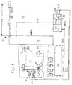
- Figure 1 shows a combine harvester (1) with a mower (MW), which on a grain edge (GK) one Grain field (GF) while observing one if possible slight deviation from a given Side edge of grain (GKS) automatically regulated should drive along.
- MW a mower
- GK grain edge
- GKS Side edge of grain
- OV location device
- OST location beam area
- ST control device
- the control device (ST) via a standardized data bus (CAN) with a Central processor (ZP) connected, through which the rest Control processes of the combine are monitored.
- a Central processor (ZP) connected to the control device (ST).
- E input keyboard on the central processor
- AV output device
- the central processor (ZP) takes from the Front edges (VR) on a speed signal (VS).
- the steering hydraulics (LH) are controlled by the control device (ST). by means of a left control valve (LV) and one Right-hand control valve (RV) controlled, its hydraulic Outputs act on the existing steering hydraulics (LH), which causes the rear wheels to turn.
- LV left control valve
- RV Right-hand control valve
- the Steering control valves (LV, RV) are self-locking when spring-loaded executed so that they are closed in the event of a power failure. In this state, the steering is directly over the Known hydraulic control from the steering wheel (R) performed. In the operator's cabin there are also a Hand switch (HS), a foot switch (FS) and one Safety switch (NS) arranged, the signals of the Steering control valve arrangement supplied for safety reasons are and the control device (ST) for their activation made available when these signals are complete are.
- HS Hand switch
- FS foot switch
- NS Safety switch
- the locating device feeds its standardized locating signal (NOS) analog or preferably already digitized generated in the control device (ST).
- NOS standardized locating signal
- ST control device
- the others Sensors which generate the other input variables, are generally distributed in the combine and give their signals, possibly via associated digitizers and computer, also to the control device.
- their normalizers can also associated directly installed there on the sensors be.
- LSG steering manipulated variables
- control device by means of a digital The computer enables the complete integration of the Steering system in the rest of the digital control of the Combine harvester.
- processor By simple parameterization and by an operation from the central operating console of the Harvester parameters are the processor given; the control device itself is in its Basic structure completely neutral.
- the most varied Location systems can be easily parameterized and normalize the signals, and it's not one special hardware design of the control device required for this.
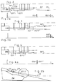
- Figure 2 shows a top view of a locating device (OV) with two at an angle (HW) of about 5 ° divergent location beams (OST1, OST2), which over the mower (MW) on the one hand into the grain field (GF) and on the other hand next to the crop edge (GK) on the Stubble field fall. Accordingly, one results in each case temporal echo signal (OS1, OS2), as shown in FIG. 2, too early and late.
- These two location signals (OS1, OS2) are identified by a Separate time filtering and show their presence the correct alignment of the mower (MW) Grain edge (GK) is within specified limits.
- Fig. 3 shows a shift of the grain edge (GK *) from the edge of the mower. Accordingly, the two rays hit (OST1, OST2) on the stubble field and they arise late location signals (OS1 *, OS2 *) as in FIG. 3 shows. From the side view of Figure 2b it can be seen that the location beams (OST1, OST2) by a vertical angle (VW) offset from the locating device (OV) be, whereby the location signals (OS1 *, OS2 *) late in time but slightly offset from each other occur.
- VW vertical angle
- FIG 4 shows another case in which the Grain edge (GK2 '') is offset from the target position, so that the two location beams (OST1, OST2) into the Grain field fall. Because of this and because of the Vertical offset (VW) of the beams arise in one early two slightly offset Echo signals (OS1 '', OS2 '') as shown in Figure 4a.
- GK2 '' the Grain edge
- VW Vertical offset
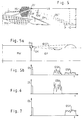
- Figure 5 shows a second embodiment Side view of the mower (MW) of the combine (1) in the Area of the grain edge (GK) and the location beam area (EAST).
- the associated locating device (OV) is on a carrier (OT) at a height (H) of about 1 m - 1.5 m above the ground in the front area of the mower (MW) arranged. The cheapest height is 200 mm - 400 mm over the ears.
- the location beam area (OST) is 15 ° - 25 ° inclined to the horizontal, partly to the ground and partly aimed at the grain edge (GK), so that it around an advance distance (VA) of 4 to 6 m covers the ground.
- the solid angle (OW) of the location beam area that is captured is approximately 8 ° for 50% of the signal component and approximately 16 ° for 90% of the signal component. The one caught on the ground
- the area has a diameter (D) of approx. 2 m.
- Figure 5a shows in the supervision that the Beam club or the beam fan in the correct position of the mower to the grain edge in a close range to Mower meets the grain and in the far area to other part on the stubble field. Accordingly arise two echo signals (OSN, OSF) of approximately the same, middle Amlitude in near and distant Area as shown in Figure 5.
- FIGS. 6 and 7 each show the echo signals (OSN *, OSF *) for the two different ones from the normal position deviating positions of the mower, which is approximately double Have amplitude and alone, either early or late, on.
- the echo on the grain may be highly structured if the stalks are of different heights have or are kinked. It is therefore recommended the early and the late echo signal each time integrate and so quasi the area of the signal to bring to the evaluation.
- the signals are either related to each other and the quotient with a comparative value that generally One is compared, and the result is used for regulation in a standardized manner.
- One of the echo signals can also be used alone, the early or the late, by comparison with one predetermined value, which is about half of the full value corresponds to that at full in the grain inventory or full Locating beam directed towards the stubble field (OST) arises, use as a standard location signal (NOS). At This has the correct alignment of the mower to the crop standardized location signal (NOS) for example the value zero.
Landscapes
- Life Sciences & Earth Sciences (AREA)
- Environmental Sciences (AREA)
- Engineering & Computer Science (AREA)
- Mechanical Engineering (AREA)
- Soil Sciences (AREA)
- Guiding Agricultural Machines (AREA)
- Harvester Elements (AREA)
Applications Claiming Priority (2)
| Application Number | Priority Date | Filing Date | Title |
|---|---|---|---|
| DE19508942 | 1995-03-13 | ||
| DE19508942A DE19508942A1 (de) | 1995-03-13 | 1995-03-13 | Reflex-Ortungsvorrichtung |
Publications (2)
| Publication Number | Publication Date |
|---|---|
| EP0732045A1 EP0732045A1 (de) | 1996-09-18 |
| EP0732045B1 true EP0732045B1 (de) | 1999-05-26 |
Family
ID=7756492
Family Applications (1)
| Application Number | Title | Priority Date | Filing Date |
|---|---|---|---|
| EP96101457A Expired - Lifetime EP0732045B1 (de) | 1995-03-13 | 1996-02-02 | Reflex-Ortungsvorrichtung |
Country Status (5)
| Country | Link |
|---|---|
| US (1) | US5715666A (da) |
| EP (1) | EP0732045B1 (da) |
| BR (1) | BR9600995A (da) |
| DE (2) | DE19508942A1 (da) |
| DK (1) | DK0732045T3 (da) |
Families Citing this family (23)
| Publication number | Priority date | Publication date | Assignee | Title |
|---|---|---|---|---|
| DE19719939A1 (de) * | 1997-05-13 | 1998-11-19 | Claas Ohg | Automatisch lenkbare Erntemaschine |
| DE29724569U1 (de) | 1997-06-25 | 2002-05-16 | Claas Selbstfahrende Erntemaschinen GmbH, 33428 Harsewinkel | Vorrichtung an Landmaschinen zur berührungslosen Abtastung von sich über dem Boden erstreckender Konturen |
| DE19743884C2 (de) | 1997-10-04 | 2003-10-09 | Claas Selbstfahr Erntemasch | Vorrichtung und Verfahren zur berührungslosen Erkennung von Bearbeitungsgrenzen oder entsprechenden Leitgrößen |
| DE19845666B4 (de) | 1998-10-05 | 2005-08-25 | Claas Selbstfahrende Erntemaschinen Gmbh | Lenkautomatik mit Ultraschall-Ortungsvorrichtung |
| DE19853085B4 (de) | 1998-11-18 | 2014-03-20 | Claas Selbstfahrende Erntemaschinen Gmbh | Verfahren zum Justieren einer an einer Feldmaschine befestigten Sensoreinheit sowie eine Justiereinrichtung und eine Feldmaschine |
| US6119442A (en) * | 1999-05-14 | 2000-09-19 | Case Corporation | Combine setting autoadjust with machine vision |
| US6615570B2 (en) * | 2001-06-28 | 2003-09-09 | Deere & Company | Header position control with forward contour prediction |
| US6661524B2 (en) * | 2001-07-09 | 2003-12-09 | United Defense, L.P. | Vehicle regional scanner |
| DE10204702A1 (de) | 2002-02-05 | 2003-08-14 | Claas Selbstfahr Erntemasch | Ortungssystem an selbstfahrenden landwirtschaftlichen Arbeitsmaschinen |
| DE10227484A1 (de) * | 2002-06-19 | 2004-02-26 | Claas Selbstfahrende Erntemaschinen Gmbh | Vorrichtung und Verfahren zur Lagesteuerung eines Erntegutaufnahmegerätes landwirtschaftlicher Erntemaschinen |
| US8855405B2 (en) * | 2003-04-30 | 2014-10-07 | Deere & Company | System and method for detecting and analyzing features in an agricultural field for vehicle guidance |
| US8712144B2 (en) * | 2003-04-30 | 2014-04-29 | Deere & Company | System and method for detecting crop rows in an agricultural field |
| US8737720B2 (en) * | 2003-04-30 | 2014-05-27 | Deere & Company | System and method for detecting and analyzing features in an agricultural field |
| US20060185340A1 (en) * | 2003-05-19 | 2006-08-24 | Eyre Robert J | Cutting and threshing header for harvesting machine |
| US7916898B2 (en) * | 2003-09-15 | 2011-03-29 | Deere & Company | Method and system for identifying an edge of a crop |
| DE10342922A1 (de) * | 2003-09-15 | 2005-05-19 | Claas Selbstfahrende Erntemaschinen Gmbh | Häcksel- und Verteilvorrichtung |
| US7412905B1 (en) | 2004-05-31 | 2008-08-19 | Richard Anthony Bishel | Paddle sensor |
| DE102005056553A1 (de) * | 2005-11-25 | 2007-05-31 | Claas Selbstfahrende Erntemaschinen Gmbh | Verteileinrichtung für Gutstrom |
| US7404355B2 (en) * | 2006-01-31 | 2008-07-29 | Deere & Company | Tractor and baler combination with automatic baling and tractor halt control |
| US10178828B2 (en) * | 2013-02-20 | 2019-01-15 | Deere & Company | Per plant crop sensing resolution |
| US11212962B2 (en) | 2013-02-20 | 2022-01-04 | Deere & Company | Field condition determination |
| US9585309B2 (en) * | 2015-07-14 | 2017-03-07 | Cnh Industrial America Llc | Header height control system for an agricultural harvester |
| US9706697B2 (en) * | 2015-07-29 | 2017-07-18 | Claas Omaha, Inc. | Agricultural system with a baler and tow tractor and a steering arrangement by which the baler is steered autonomously |
Family Cites Families (17)
| Publication number | Priority date | Publication date | Assignee | Title |
|---|---|---|---|---|
| US3797208A (en) * | 1970-10-23 | 1974-03-19 | Clayson Nv | Mechanism for the automatic steering of agricultural machines, especially combines |
| DE2109744A1 (de) * | 1971-03-02 | 1972-09-07 | Klockner Humboldt Deutz AG, 5000 Köln | Einrichtung zur automatischen Be tatigung einer Servolenkung |
| BE788742A (fr) * | 1971-09-13 | 1973-01-02 | Fahr Ag Maschf | Dispositif automatique de direction pour le guidage lateral de machinesagricoles, en particulier de moissonneuses-batteuses automobiles |
| DE2224205A1 (de) * | 1972-05-18 | 1973-11-29 | Fahr Ag Maschf | Seitenfuehrungsregler fuer selbstfahrende maschinen |
| FR2254265A2 (en) * | 1973-08-14 | 1975-07-11 | Fahr Ag Maschf | Combine harvester automatic guidance system - has sensor head near rear steering wheel, pickups, travel stops, and program changeover |
| DE2455836C3 (de) * | 1974-11-26 | 1982-01-21 | Gebr.Claas Maschinenfabrik GmbH, 4834 Harsewinkel | Einrichtung zur selbsttätigen Führung landwirtschaftlicher Arbeitsmaschinen |
| US4077488A (en) * | 1976-06-15 | 1978-03-07 | Sperry Rand Corporation | Guidance assist system for agricultural machines |
| DE3627015A1 (de) * | 1986-08-09 | 1988-02-11 | Krupp Gmbh | Automatisches regelsystem fuer eine kontinuierliche schnittkantenregelung |
| EP0375301B1 (en) * | 1988-12-22 | 1994-06-15 | New Holland Belgium N.V. | Row crop harvester guidance system |
| US4918441A (en) * | 1988-12-22 | 1990-04-17 | Ford New Holland, Inc. | Non-contact sensing unit for row crop harvester guidance system |
| US5019983A (en) * | 1989-02-21 | 1991-05-28 | Eaton Corporation | Automatic steering apparatus using reflected signals |
| JP2583641B2 (ja) * | 1990-05-18 | 1997-02-19 | 日産自動車株式会社 | 走行制御方法 |
| DE9103030U1 (de) * | 1991-03-13 | 1991-06-20 | Moba-Electronic Gesellschaft für Mobil-Automation mbH, 6254 Elz | Ultraschall-Abstandsmeßeinrichtung, insbesondere zur Steuerung einer Baumaschine oder einer landwirtschaftlichen Maschine |
| US5410479A (en) * | 1992-08-17 | 1995-04-25 | Coker; William B. | Ultrasonic furrow or crop row following sensor |
| EP0774383A3 (en) * | 1993-06-28 | 1999-05-26 | New Holland Belgium N.V. | Process for the control of self-propelled agricultural harvesting machines |
| US5754099A (en) * | 1994-03-25 | 1998-05-19 | Nippondenso Co., Ltd. | Obstacle warning system for a vehicle |
| US5606504A (en) * | 1995-02-17 | 1997-02-25 | Lockheed Martin Corporation | Crop swath-width measurement using acoustic transducers |
-
1995
- 1995-03-13 DE DE19508942A patent/DE19508942A1/de not_active Withdrawn
-
1996
- 1996-02-02 EP EP96101457A patent/EP0732045B1/de not_active Expired - Lifetime
- 1996-02-02 DK DK96101457T patent/DK0732045T3/da active
- 1996-02-02 DE DE59601968T patent/DE59601968D1/de not_active Expired - Lifetime
- 1996-03-08 US US08/613,045 patent/US5715666A/en not_active Expired - Lifetime
- 1996-03-12 BR BR9600995A patent/BR9600995A/pt not_active IP Right Cessation
Also Published As
| Publication number | Publication date |
|---|---|
| DE19508942A1 (de) | 1996-09-19 |
| DK0732045T3 (da) | 1999-12-06 |
| DE59601968D1 (de) | 1999-07-01 |
| EP0732045A1 (de) | 1996-09-18 |
| BR9600995A (pt) | 1997-12-30 |
| US5715666A (en) | 1998-02-10 |
Similar Documents
| Publication | Publication Date | Title |
|---|---|---|
| EP0732045B1 (de) | Reflex-Ortungsvorrichtung | |
| EP0878121B1 (de) | Automatisch lenkbare Erntemaschine | |
| EP3569049B1 (de) | Landwirtschaftliche arbeitsmaschine | |
| EP1630574B1 (de) | Vorrichtung an Landmaschinen zur berührungslosen Abtastung von sich über dem Boden erstreckenden Konturen | |
| EP0732046B1 (de) | Ortungsvorrichtung | |
| EP1266553B1 (de) | Einrichtung zur selbsttätigen Lenkung eines landwirtschaftlichen Arbeitsfahrzeugs | |
| EP3165062B1 (de) | Landwirtschaftliche arbeitsmaschine mit einer umfelddetektionseinrichtung | |
| EP0906720B2 (de) | Vorrichtung und Verfahren zur berührungslosen Erkennung von Bearbeitungsgrenzen oder entsprechenden Leitgrössen | |
| EP1266552B1 (de) | Einrichtung zur Positionsbestimmung eines landwirtschaftlichen Arbeitsfahrzeugs | |
| EP0131693B1 (de) | Erntemaschine mit einem automatisch steuerbaren beweglichen, das Erntegut ausstossenden Stutzen | |
| EP1266554B1 (de) | Einrichtung zur selbsttätigen Lenkung eines landwirtschaftlichen Arbeitsfahrzeugs | |
| EP2278869A1 (de) | Verfahren und vorrichtung zur lenkung einer zweiten landwirtschaftlichen maschine, die parallel fahrend zu einer ersten landwirtschaftlichen maschine über ein feld lenkbar ist | |
| EP0732043A1 (de) | Selbstlenkvorrichtung | |
| EP3530098B1 (de) | Verfahren zur ermittlung der bestandsdichte eines feldbestands | |
| EP0992185B1 (de) | Lenkautomatik mit Ultraschall-Ortungsvorrichtung | |
| EP3300561A1 (de) | Selbstfahrende landwirtschaftliche arbeitsmaschine | |
| DE2455836C3 (de) | Einrichtung zur selbsttätigen Führung landwirtschaftlicher Arbeitsmaschinen | |
| EP3530099B1 (de) | Selbstfahrende erntemaschine | |
| EP3738420B1 (de) | Verfahren für den betrieb einer selbstfahrenden landwirtschaftlichen arbeitsmaschine | |
| DE2145717A1 (de) | Automatische lenkvorrichtung zur seitenfuehrung von landmaschinen, insbesondere fuer selbstfahrende maehdrescher | |
| EP1862049A1 (de) | Landmaschine | |
| EP2057875A1 (de) | Verfahren und Anordnung zur Erfassung des Pflanzenbestandes auf Landmaschinen |
Legal Events
| Date | Code | Title | Description |
|---|---|---|---|
| PUAI | Public reference made under article 153(3) epc to a published international application that has entered the european phase |
Free format text: ORIGINAL CODE: 0009012 |
|
| 17P | Request for examination filed |
Effective date: 19960705 |
|
| AK | Designated contracting states |
Kind code of ref document: A1 Designated state(s): BE DE DK FR GB IT |
|
| GRAG | Despatch of communication of intention to grant |
Free format text: ORIGINAL CODE: EPIDOS AGRA |
|
| GRAG | Despatch of communication of intention to grant |
Free format text: ORIGINAL CODE: EPIDOS AGRA |
|
| GRAH | Despatch of communication of intention to grant a patent |
Free format text: ORIGINAL CODE: EPIDOS IGRA |
|
| GRAH | Despatch of communication of intention to grant a patent |
Free format text: ORIGINAL CODE: EPIDOS IGRA |
|
| 17Q | First examination report despatched |
Effective date: 19981117 |
|
| ITF | It: translation for a ep patent filed | ||
| GRAA | (expected) grant |
Free format text: ORIGINAL CODE: 0009210 |
|
| AK | Designated contracting states |
Kind code of ref document: B1 Designated state(s): BE DE DK FR GB IT |
|
| ET | Fr: translation filed | ||
| REF | Corresponds to: |
Ref document number: 59601968 Country of ref document: DE Date of ref document: 19990701 |
|
| GBT | Gb: translation of ep patent filed (gb section 77(6)(a)/1977) |
Effective date: 19990709 |
|
| REG | Reference to a national code |
Ref country code: DK Ref legal event code: T3 |
|
| PLBE | No opposition filed within time limit |
Free format text: ORIGINAL CODE: 0009261 |
|
| STAA | Information on the status of an ep patent application or granted ep patent |
Free format text: STATUS: NO OPPOSITION FILED WITHIN TIME LIMIT |
|
| 26N | No opposition filed | ||
| REG | Reference to a national code |
Ref country code: GB Ref legal event code: IF02 |
|
| PG25 | Lapsed in a contracting state [announced via postgrant information from national office to epo] |
Ref country code: IT Free format text: LAPSE BECAUSE OF NON-PAYMENT OF DUE FEES Effective date: 20050202 |
|
| PGFP | Annual fee paid to national office [announced via postgrant information from national office to epo] |
Ref country code: FR Payment date: 20120228 Year of fee payment: 17 |
|
| PGFP | Annual fee paid to national office [announced via postgrant information from national office to epo] |
Ref country code: DK Payment date: 20120216 Year of fee payment: 17 Ref country code: GB Payment date: 20120222 Year of fee payment: 17 Ref country code: BE Payment date: 20120221 Year of fee payment: 17 |
|
| REG | Reference to a national code |
Ref country code: DE Ref legal event code: R084 Ref document number: 59601968 Country of ref document: DE Effective date: 20121218 |
|
| PGFP | Annual fee paid to national office [announced via postgrant information from national office to epo] |
Ref country code: DE Payment date: 20121227 Year of fee payment: 18 |
|
| BERE | Be: lapsed |
Owner name: *CLAAS K.G.A.A. Effective date: 20130228 |
|
| REG | Reference to a national code |
Ref country code: DK Ref legal event code: EBP |
|
| GBPC | Gb: european patent ceased through non-payment of renewal fee |
Effective date: 20130202 |
|
| REG | Reference to a national code |
Ref country code: FR Ref legal event code: ST Effective date: 20131031 |
|
| PG25 | Lapsed in a contracting state [announced via postgrant information from national office to epo] |
Ref country code: DK Free format text: LAPSE BECAUSE OF NON-PAYMENT OF DUE FEES Effective date: 20130228 Ref country code: GB Free format text: LAPSE BECAUSE OF NON-PAYMENT OF DUE FEES Effective date: 20130202 Ref country code: FR Free format text: LAPSE BECAUSE OF NON-PAYMENT OF DUE FEES Effective date: 20130228 Ref country code: BE Free format text: LAPSE BECAUSE OF NON-PAYMENT OF DUE FEES Effective date: 20130228 |
|
| REG | Reference to a national code |
Ref country code: DE Ref legal event code: R119 Ref document number: 59601968 Country of ref document: DE |
|
| REG | Reference to a national code |
Ref country code: DE Ref legal event code: R119 Ref document number: 59601968 Country of ref document: DE Effective date: 20140902 |
|
| PG25 | Lapsed in a contracting state [announced via postgrant information from national office to epo] |
Ref country code: DE Free format text: LAPSE BECAUSE OF NON-PAYMENT OF DUE FEES Effective date: 20140902 |