EP0732164A1 - Outil de perçage, en particulier pour le perçage par percussion de la pierre - Google Patents
Outil de perçage, en particulier pour le perçage par percussion de la pierre Download PDFInfo
- Publication number
- EP0732164A1 EP0732164A1 EP96103615A EP96103615A EP0732164A1 EP 0732164 A1 EP0732164 A1 EP 0732164A1 EP 96103615 A EP96103615 A EP 96103615A EP 96103615 A EP96103615 A EP 96103615A EP 0732164 A1 EP0732164 A1 EP 0732164A1
- Authority
- EP
- European Patent Office
- Prior art keywords
- drill
- drilling tool
- holding means
- tool according
- shaft
- Prior art date
- Legal status (The legal status is an assumption and is not a legal conclusion. Google has not performed a legal analysis and makes no representation as to the accuracy of the status listed.)
- Granted
Links
- 238000005553 drilling Methods 0.000 title claims abstract description 67
- 239000004575 stone Substances 0.000 title 1
- 239000011435 rock Substances 0.000 claims description 6
- 230000007704 transition Effects 0.000 claims description 3
- 230000004323 axial length Effects 0.000 claims 1
- 230000000694 effects Effects 0.000 abstract description 2
- 239000011324 bead Substances 0.000 description 3
- 238000013461 design Methods 0.000 description 2
- 230000005540 biological transmission Effects 0.000 description 1
- 230000006378 damage Effects 0.000 description 1
- 238000011161 development Methods 0.000 description 1
- 230000018109 developmental process Effects 0.000 description 1
- 238000003780 insertion Methods 0.000 description 1
- 230000037431 insertion Effects 0.000 description 1
- 239000000463 material Substances 0.000 description 1
- 230000003534 oscillatory effect Effects 0.000 description 1
- 230000000149 penetrating effect Effects 0.000 description 1
- 230000000717 retained effect Effects 0.000 description 1
- 239000007787 solid Substances 0.000 description 1
- 239000011343 solid material Substances 0.000 description 1
- 238000012549 training Methods 0.000 description 1
Images


Classifications
-
- B—PERFORMING OPERATIONS; TRANSPORTING
- B23—MACHINE TOOLS; METAL-WORKING NOT OTHERWISE PROVIDED FOR
- B23B—TURNING; BORING
- B23B51/00—Tools for drilling machines
- B23B51/04—Drills for trepanning
- B23B51/0473—Details about the connection between the driven shaft and the tubular cutting part; Arbors
-
- E—FIXED CONSTRUCTIONS
- E21—EARTH OR ROCK DRILLING; MINING
- E21B—EARTH OR ROCK DRILLING; OBTAINING OIL, GAS, WATER, SOLUBLE OR MELTABLE MATERIALS OR A SLURRY OF MINERALS FROM WELLS
- E21B10/00—Drill bits
- E21B10/36—Percussion drill bits
- E21B10/40—Percussion drill bits with leading portion
-
- E—FIXED CONSTRUCTIONS
- E21—EARTH OR ROCK DRILLING; MINING
- E21B—EARTH OR ROCK DRILLING; OBTAINING OIL, GAS, WATER, SOLUBLE OR MELTABLE MATERIALS OR A SLURRY OF MINERALS FROM WELLS
- E21B10/00—Drill bits
- E21B10/62—Drill bits characterised by parts, e.g. cutting elements, which are detachable or adjustable
-
- Y—GENERAL TAGGING OF NEW TECHNOLOGICAL DEVELOPMENTS; GENERAL TAGGING OF CROSS-SECTIONAL TECHNOLOGIES SPANNING OVER SEVERAL SECTIONS OF THE IPC; TECHNICAL SUBJECTS COVERED BY FORMER USPC CROSS-REFERENCE ART COLLECTIONS [XRACs] AND DIGESTS
- Y10—TECHNICAL SUBJECTS COVERED BY FORMER USPC
- Y10T—TECHNICAL SUBJECTS COVERED BY FORMER US CLASSIFICATION
- Y10T279/00—Chucks or sockets
- Y10T279/17—Socket type
- Y10T279/17042—Lost motion
- Y10T279/17085—Key retainer
-
- Y—GENERAL TAGGING OF NEW TECHNOLOGICAL DEVELOPMENTS; GENERAL TAGGING OF CROSS-SECTIONAL TECHNOLOGIES SPANNING OVER SEVERAL SECTIONS OF THE IPC; TECHNICAL SUBJECTS COVERED BY FORMER USPC CROSS-REFERENCE ART COLLECTIONS [XRACs] AND DIGESTS
- Y10—TECHNICAL SUBJECTS COVERED BY FORMER USPC
- Y10T—TECHNICAL SUBJECTS COVERED BY FORMER US CLASSIFICATION
- Y10T408/00—Cutting by use of rotating axially moving tool
- Y10T408/89—Tool or Tool with support
- Y10T408/895—Having axial, core-receiving central portion
-
- Y—GENERAL TAGGING OF NEW TECHNOLOGICAL DEVELOPMENTS; GENERAL TAGGING OF CROSS-SECTIONAL TECHNOLOGIES SPANNING OVER SEVERAL SECTIONS OF THE IPC; TECHNICAL SUBJECTS COVERED BY FORMER USPC CROSS-REFERENCE ART COLLECTIONS [XRACs] AND DIGESTS
- Y10—TECHNICAL SUBJECTS COVERED BY FORMER USPC
- Y10T—TECHNICAL SUBJECTS COVERED BY FORMER US CLASSIFICATION
- Y10T408/00—Cutting by use of rotating axially moving tool
- Y10T408/89—Tool or Tool with support
- Y10T408/905—Having stepped cutting edges
- Y10T408/906—Axially spaced
-
- Y—GENERAL TAGGING OF NEW TECHNOLOGICAL DEVELOPMENTS; GENERAL TAGGING OF CROSS-SECTIONAL TECHNOLOGIES SPANNING OVER SEVERAL SECTIONS OF THE IPC; TECHNICAL SUBJECTS COVERED BY FORMER USPC CROSS-REFERENCE ART COLLECTIONS [XRACs] AND DIGESTS
- Y10—TECHNICAL SUBJECTS COVERED BY FORMER USPC
- Y10T—TECHNICAL SUBJECTS COVERED BY FORMER US CLASSIFICATION
- Y10T408/00—Cutting by use of rotating axially moving tool
- Y10T408/89—Tool or Tool with support
- Y10T408/907—Tool or Tool with support including detailed shank
Definitions
- the invention relates to a drilling tool, in particular for rotary drilling of preferably rock, according to the preamble of claim 1.
- Drilling tools and in particular rock drills are used to create breakthroughs in concrete or masonry and are especially designed for use in rotary hammers.
- So-called drill bits such as are shown, for example, in DE 33 22 887, are generally used to produce larger openings.
- Such a drill bit consists of a pot-shaped housing with carbide cutting inserts arranged on the end face.
- a concentrically inserted center drill is used for centering, especially when drilling into the rock material.
- breakthrough drills which generally consist of a solid drill head, have also become known for producing generally smaller breakthroughs, the drill shank being provided with a one-piece or separate feed helix (DE 28 56 205 A1; DE 36 14 010 A1).
- the rock drill according to DE 28 56 205 also has one Pot-shaped cross drill head with a separately usable center drill.
- this bore for receiving the centering drill is generally of a conical shape in order to receive a likewise conical centering drill shaft.
- the exchange after long operation of the drilling tool can, however, turn out to be problematic, since the clamping effect of the conical surfaces is so great that the center drill cannot be easily removed.
- DE 33 22 887 provides, for example, a transverse bore into which the end of the centering drill protrudes. The center drill can then be pressed out using a separate tool.
- Such a transverse recess at the end of the conical seat in the drill bit shaft represents a cross-sectional disorder that affects the transmission of impact movements.
- the cross section of the tool shank is disadvantageously weakened.
- DE 33 22 887 also has a securing element on the centering drill, which is designed as a separate ring and is intended to prevent it falling out during operation. However, this device only serves to prevent the center drill from falling out unintentionally. Normally, the center drill sits firmly in the drill bit due to the conical frictional connection.
- the center drill is recessed in the area of the penetrating screw in the longitudinal direction of the drill so that, if necessary, the drill can also be moved axially.
- the subject of utility model DE-U1-85 21 577 also shows a drill bit with an axially movable center drill, with laterally arranged set screws projecting into the receiving bore for the center drill.
- the center drill is designed as a known "SDS drill", which has longitudinal grooves for a separate rotary drive and an axial securing device with separate elements. Such a tool enables a known SDS drill to be used cost-effectively. However, the mechanical effort on the shaft of the drill bit is considerable.
- the disadvantage of the known solutions with an axially movable center drill is also that, during the rotary impact drilling, the center drill performs longitudinal and torsional vibratory movements with respect to the rest of the tool, which lead to destruction of the holding means for the center drill under heavy use. In particular, the thread of a transverse retaining pin is destroyed relatively quickly by these vibrations. Also the A large number of the individual parts used in accordance with utility model GM 85 21 577 are subject to high wear when subjected to impact with an axially displaceable center drill.
- the fixed attachment of the center drill for example by means of a conical seat, also has the disadvantage that the drilling capacity is significantly reduced compared to an embodiment in which the center drill itself can be caused to oscillate axially by a striking load.
- the invention has for its object to avoid the disadvantages of the prior art explained above and in particular to provide a holder for a center drill in a drilling tool, which is particularly intended for a rotary impact and long service life, easy interchangeability of the center drill and improved Has drilling performance.
- the invention is based on the main idea that a drilling tool, in particular for rotary drilling of rock, is advantageously to be provided with an exchangeable center drill which is designed as a wearing part.
- the center drill itself should be mounted so that it can move axially within its receiving bore in order to be subjected to impact, whereby According to the invention, the center drill is secured against falling out via a rod-shaped or tubular holding element.
- the pin-like holding means for example in the drill bit shank or in the drill head of a breakthrough drill, consequently penetrates into the receiving bore of the center drill off-center and almost tangentially to the center drill.
- the center drill can perform longitudinal oscillating movements in the axial direction, the bore for receiving the center drill being preferably configured such that the bottom of the bore serves at the same time as stops for the center drill end in order to prevent the axial impacts of the drilling tool on the Transfer center drill. Due to the axial mobility of the center drill, the center drill can perform oscillatory movements relative to the other drilling tool. This avoids a reduction in the drilling capacity, as is the case, for example, in an embodiment with a fixed center drill.
- the center drill, including its holding means is subject to almost no wear in this area. Furthermore, the exchange of holder and / or center drill is easily possible. Due to the off-center bracket on the center drill ensures that a reliable rotary driving of the center drill is guaranteed.
- Such an arrangement can be used without problems both with a drill bit and, for example, with known breakthrough drills in order to be able to use exchangeable center drills.
- the recess for receiving the holding means penetrates the drilling tool completely in the transverse direction.
- the rod-shaped or tubular holding means can be removed in a simple manner.
- the invention provides holding means which are arranged loosely within the transverse bore. In this case, falling out is taken by means of additional slip-on measures which prevent the holding means from escaping to the side.
- the holding means itself can also be arranged non-positively within the transverse recess or bore, preferably so-called dowel pins proving to be inexpensive. These can simply be knocked out to the side.
- the present invention can basically be implemented on various drilling tools, as is shown, for example, in FIGS. 1, 2, 7 and 10.
- the centering drill according to the invention can be held in a drill bit or also in a breakthrough drill with a cross cutting head or the like.
- a first embodiment of a drilling tool 1 which comprises a drill bit 2, which is integrally connected to a shaft part 4.
- the basic structure of such a drill bit is described in DE 33 22 887. This is referred to.
- the shaft part 4 has a central bore 5 which serves to receive a centering bore 6.
- the cylindrical bore 5 in the shaft part 4 and the cylindrical shaft part 7 of the center drill 6 are matched to one another in such a way that the center drill 6 can move axially, which is indicated by the arrow 8.
- the axial mobility of the center drill 6 is achieved by a lateral plane recess 9 or flattening 9, which is located at a short distance h1 behind the stop surface 10 of the center drill 6 and extends over a height section h2.
- the center drill 6 protrudes in the bore 5 with its stop surface 10 to the bottom 11 of the bore 5 and is subjected to a striking stress from here.
- the center drill 6 does not fall out of the bore 5 of the drilling tool 1 due to its axial mobility, it is held by a rod-shaped or tubular holding means 12, which is also designed, for example, as a cylindrical pin 12 and is located in one Cross bore 13 is located in the shaft part 4 of the drilling tool 1.
- the transverse bore 13 is arranged eccentrically with its bore longitudinal axis 14 by an amount e relative to the transverse axis of symmetry 15 of the shaft part 4 or the drill longitudinal axis 44.
- the eccentricity e is dimensioned so large that the transverse holding means 12 lies tangentially against the flat recess 9 of the centering drill 6 and thus causes a rotary drive over this surface section. Falling out of the center drill 6 is brought about by the end-side cylinder section 16 with the height h1, ie the center drill 6 can move axially within the bore 5 of the drilling tool 1 without falling out of the bore.
- rod-like or tube-like holding means 12 which is also embodied, for example, as a cylindrical pin in FIGS. 1a, b, is designed differently.
- the locking ring 17 prevents it from falling out laterally.
- the locking ring 17 covers the transverse bore 13 and is pushed onto the cylindrical shaft part 4.
- this has a bead 18 which interacts with an angled groove 19 in a bayonet-like manner.
- the bead 18 is first screwed down over a vertical groove part 20 and then into a horizontal groove part 21.
- the groove depth of the horizontal groove part 21 can decrease in the direction of the groove end, as a result of which the bead 18 jams.
- FIGS. 2a, b A further exemplary embodiment of a drilling tool with a drill bit 2 is shown in FIGS. 2a, b.
- the same parts are designated with the same reference numerals as for Fig. 1a.
- the centering drill 6 is in turn positioned and secured by a rod-shaped and tubular holding means 12 in the shaft part 4, a spring element 22 being used to secure the cylindrical holding element 12 in the transverse bore 13.
- the spring element 22 closes with its two angled ends 23, 23 'the two lateral openings 24, 24' of the transverse bore 13 in the drill bit shaft 4.
- the holding means 12 which is movably arranged in the transverse bore 13 cannot fall out during use of the drilling tool.
- the spring element 22 extends a little more than half the circumference of the shaft part 4 at this point, whereby the spring element 22 can be clipped on.
- the spring element 22 is pulled off with the aid of a tab 26 bent upwards, the cylindrical holding element 12 is removed and the centering drill 6 is pulled out of the bore 5. No tools are required for this.
- FIGS. 3 to 6 four different exemplary embodiments with a centering drill holder according to the invention are shown in a sectional plan view, as this corresponds in principle to FIG. 1b. Identical parts may be provided with the same reference symbols.
- a spring element is used to secure and position the rod-shaped or tubular holding means 12.
- the various spring elements are designated with reference numerals 27 to 30.
- the respective Spring element 27 to 30 guided in a groove 25. This prevents the respective spring element 27 to 30 from being knocked off or detached when the drill bit is used in a rotationally rotating manner.
- the center drill 6, as described for FIGS. 1 and 2 is positioned and secured with longitudinal play by the pin-like holding means 12 in the bore 5 of the drilling tool 1.
- the spring element 27 engages on one side in the lateral opening 24 'of the transverse bore 13, in which the holding means 12 is movably arranged.
- the end of the spring element 27 covers the other opening 24 of the transverse bore 13.
- the holding means 12 is thus clearly secured against falling out.
- the spring element 27 guided in the groove 25 is self-locking, since it encloses a larger area than half the circumference of the drill bit shank 4. It is also locked in position by the end bent into the opening 24 '.
- FIG. 4 shows a further exemplary embodiment, both ends of the spring element 28 engaging in the respective openings 24, 24 ′ of the transverse bore 13 in order to secure the holding means 12.
- FIG. 5 shows a further exemplary embodiment, in which the centering drill 6 is positioned and held in the shaft 4 by a modified pin-like holding means 12 ', the spring element 29 being integrally formed on the holding means 12' at one end.
- the pin-like holding means 12 'with molded-on spring element 29 only has to be pulled off the groove 25. Self-clamping is achieved in that the molded-on spring element 29 extends over a sufficiently large area of the circumference of the shaft 4.
- the centering drill 6 in the shaft 4 of the drilling tool, which is in turn positioned and secured by a cylindrical holding means 12, the pin-like holding means 12 having a head 31 provided with a slot.
- the spring element 30 guided in the groove 25 runs through the slot 32 in the head 31 of the holding means 12.
- the spring element 30 not only prevents the pin-like holding means 12 from falling out of the transverse bore 13, but also prevents the holding means from rotating about its longitudinal axis.
- the spring element 30 in turn engages on one side in the recess 24 ′ of the transverse bore, as a result of which the spring element 30 is prevented from rotating along the groove 25.
- the removal of the center drill 6 is blocked by the holding means 12.
- the pin-like holding means 12 is rotated 180 ° about its longitudinal axis, the center drill 6 can be pulled out in the axial direction in a simple manner due to a recess 33 in the pin-like holding means 12.
- the spring element 30 is also self-locking, since it encloses more than half the circumference of the drill bit shaft 4.
- the spring element 30, the pin-like holding means 12 and thus the center drill 6 can be removed and replaced without tools, as in the previous exemplary embodiments.
- the centering drill 6 is arranged in the bore 5 in the shaft part 4 of a drill bit 2 and in turn is positioned and held in the transverse bore 13 with the aid of a cylindrical holding means 12.
- the holding means 12 is positioned and secured on one side by an elastic sleeve 34 and on the other side, at the end of the transverse bore 13 on the direction of rotation, by a stop 35.
- the direction of rotation is indicated by the dash-dotted arrow 36 in Fig. 7b symbolizes.
- the elastic sleeve 34 has a correspondingly adapted, also circumferential elevation 37 which interacts with the groove 25.
- the flat, lateral recess 9 on the center drill shaft 7 is rotated, as in the exemplary embodiments described above, in such a way that the pin-like holding means 12 comes to rest along the flat recess and in the present case as far as it will go 35 can be inserted into the recess 13.
- the stop 35 absorbs all the forces that want to force the pin-like holding means 12 out of the end of the transverse bore 13 pointing in the direction of rotation due to the centrifugal force. At the opposite end of the transverse bore 13, it is entirely sufficient to fix the pin-like holding means 12 solely by means of the elastic sleeve 34. With this type of fastening according to the invention it is also possible to use the center drill 6 without tools and to replace it with a new one.
- Fig. 8 shows a further embodiment with a center drill 6, which is positioned and secured by a further cylindrical holding means 12.
- the peculiarity in this embodiment is that the holding means is curved in itself and thus braced in the transverse bore 13.
- the insertion of this holding means 12 does indeed require a tool, such as a hammer or a punch. No additional securing elements for the holding means 12 are required for this.
- the curved holding means is able to withstand the forces that occur of the center drill 6, which in turn rests with its flat recess 9 against the pin-like holding means 12 in order to bring about an axial securing and a rotational driving.
- the rest of the structure and the mode of operation correspond to the exemplary embodiments described above.
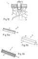
- FIGS. 9a to 9c also show alternative embodiments for the rod-shaped or tubular holding means 12.
- this holding means is essentially formed as a pin-shaped cylindrical holding means made of a solid material. This cylinder pin is inserted with play into the respective bore 13 and secured against falling out by additional measures on the outside of the shaft 4.
- FIG. 8 also shows a slightly curved cylindrical holding means 12, which due to its longitudinal axis 46 jams in the bore 13 with a curvature.
- the holding means 12 shown in FIG. 9a is a tubular holding means 12 and in particular a common dowel pin 38 according to DIN 1481 or DIN 6365.
- dowel pins are extremely inexpensive and, due to their longitudinal slot 42, can be non-positively and / or positively in the transverse bore 13 are used.
- the longitudinal slot 42 enables the outer diameter to be reduced when such a holding means is driven in, so that there is a non-positive bracing in the respective transverse bore 13. It is expedient to position the longitudinally slotted roll pin 12, 38 according to FIG. 9 a in the bore in such a way that the longitudinal slot 42 lies opposite the flat recess 9 of the center drill 6.
- FIG. 9b shows a cuboid holding means 12, the rod-shaped cuboid 39 of which has a square cross section 45 in longitudinal section.
- the transverse bore 13 can also be adapted to it have a square cross-section.
- the advantage of such an embodiment is the flat contact of a longitudinal side 40 of the cuboid 39 against the flat recess 9 of the centering drill 6, compared to a linear contact in the case of a cylindrical holding means 12.
- FIG. 9c shows a tubular holding means 12 which is designed as a polygonal body 41.
- the basic idea of the dowel pin 38 shown in FIG. 9a is combined with the surface-like support described in FIG. 9b on the flat recess 9 of the shank part 7 of the respective centering drill 6.
- the transverse bore 13 can also be cylindrical, which is fundamentally is also possible with the cuboid holding means in the embodiment according to FIG. 9b.
- the polygonal body 41 with a polygonal and in particular hexagonal cross-section is tubular, like FIG. 9a, with a longitudinal slot 42 for the purpose of bracing.
- FIG. 10 finally shows a further exemplary embodiment of the invention with a drilling tool 1 designed as a breakthrough drill 3, with an exchangeable centering drill 6.
- a drilling tool 1 designed as a breakthrough drill 3, with an exchangeable centering drill 6.
- such a tool corresponds to DE 28 56 205 mentioned at the beginning.
- the design of the embodiment according to FIG. 10 corresponds to a drilling tool, as shown for example in DE 42 36 553 by the applicant. Reference is hereby expressly made to this description of the drilling tool.
- the form in which the centering drill is arranged on the tool is left open.
- the drill head 43 again has a suitable transverse bore 13, which is located in the transition region between the drill head 43 and the feed helix 47 and in which a self-clamping holding means 12 is preferably inserted.
- a self-clamping holding means 12 is preferably inserted.
- Embodiments in particular according to FIGS. 8, 9a and 9c can be used as the self-clamping holding means.
- the self-clamping holding means 12 in turn interacts with a flat recess 9 on the shaft part 7 of the centering drill 6, the recess 9 being arranged eccentrically or eccentrically with respect to the longitudinal axis 44 of the drill in the same manner as described above.
- the attachment and positioning and locking is done in the same way as described above.
- the invention is not restricted to the exemplary embodiments shown and described. Rather, it also encompasses all professional further training within the framework of intellectual property rights claims.
Landscapes
- Engineering & Computer Science (AREA)
- Geology (AREA)
- Life Sciences & Earth Sciences (AREA)
- Mining & Mineral Resources (AREA)
- Mechanical Engineering (AREA)
- Physics & Mathematics (AREA)
- Environmental & Geological Engineering (AREA)
- Fluid Mechanics (AREA)
- General Life Sciences & Earth Sciences (AREA)
- Geochemistry & Mineralogy (AREA)
- Processing Of Stones Or Stones Resemblance Materials (AREA)
- Percussive Tools And Related Accessories (AREA)
- Earth Drilling (AREA)
Applications Claiming Priority (4)
| Application Number | Priority Date | Filing Date | Title |
|---|---|---|---|
| DE19509213 | 1995-03-17 | ||
| DE19509213 | 1995-03-17 | ||
| DE19541009 | 1995-11-03 | ||
| DE19541009A DE19541009A1 (de) | 1995-03-17 | 1995-11-03 | Bohrwerkzeug insbesondere für drehschlagendes Bohren von vorzugsweise Gestein |
Publications (2)
| Publication Number | Publication Date |
|---|---|
| EP0732164A1 true EP0732164A1 (fr) | 1996-09-18 |
| EP0732164B1 EP0732164B1 (fr) | 1999-08-25 |
Family
ID=26013365
Family Applications (1)
| Application Number | Title | Priority Date | Filing Date |
|---|---|---|---|
| EP96103615A Expired - Lifetime EP0732164B1 (fr) | 1995-03-17 | 1996-03-08 | Outil de perçage, en particulier pour le perçage par percussion de la pierre |
Country Status (4)
| Country | Link |
|---|---|
| US (1) | US5788430A (fr) |
| EP (1) | EP0732164B1 (fr) |
| JP (1) | JPH08267443A (fr) |
| DK (1) | DK0732164T3 (fr) |
Cited By (7)
| Publication number | Priority date | Publication date | Assignee | Title |
|---|---|---|---|---|
| US6116827A (en) * | 1997-09-13 | 2000-09-12 | Hawera Probst Gmbh | Drilling tool |
| DE19748987B4 (de) * | 1997-11-06 | 2007-11-22 | Robert Bosch Gmbh | Bohrwerkzeug insbesondere für drehschlagendes Bohren von vorzugsweise Gestein |
| US7488146B2 (en) | 2006-11-16 | 2009-02-10 | Black & Decker Inc. | Large holesaw mandrel assembly |
| US7517179B2 (en) | 2006-11-16 | 2009-04-14 | Black & Decker Inc. | Small holesaw mandrel assembly |
| EP2465627A1 (fr) * | 2010-12-14 | 2012-06-20 | DreBo Werkzeugfabrik GmbH | Outil de forage |
| US8434976B2 (en) | 2009-03-20 | 2013-05-07 | Black & Decker Inc. | Small hole saw mandrel assembly |
| EP3444055A1 (fr) * | 2017-08-18 | 2019-02-20 | Udo Zirden | Mandrin de serrage destiné au serrage d'un outil rotatif |
Families Citing this family (15)
| Publication number | Priority date | Publication date | Assignee | Title |
|---|---|---|---|---|
| GB0005937D0 (en) * | 2000-03-10 | 2000-05-03 | Black & Decker Inc | Interlock mechanism |
| US6510904B1 (en) | 2000-05-26 | 2003-01-28 | Nippon Pneumatic Mfg. Co., Ltd. | Protected tool bushing for an impact hammer |
| GB2393931A (en) * | 2002-10-10 | 2004-04-14 | Black & Decker Inc | Tool for a rotary hammer |
| EP1493766B1 (fr) * | 2003-06-30 | 2006-06-07 | Mitsubishi Gas Chemical Company, Inc. | Composition de résine reticulable à la chaleur et utilisation de celle-ci |
| FR2863533B1 (fr) * | 2003-12-15 | 2007-05-04 | Montabert Roger | Dispositif de retenue d'une clavette d'outil pour appareil de demolition a percussion |
| US7363433B2 (en) * | 2005-02-09 | 2008-04-22 | International Business Machines Corporation | Cache member protection with partial make MRU allocation |
| US7343455B2 (en) * | 2005-02-09 | 2008-03-11 | International Business Machines Corporation | Cache mechanism and method for avoiding cast out on bad victim select and recycling victim select operation |
| US7419017B2 (en) * | 2005-06-10 | 2008-09-02 | Keystone Drill Services, Inc. | Multi-sectional percussive drill bit assembly |
| US7395883B2 (en) * | 2005-12-15 | 2008-07-08 | Rockmore International, Inc. | Keyed connection for drill bit |
| US20080150302A1 (en) * | 2006-03-02 | 2008-06-26 | Chung-Liang Lin | Bolt Assembly for Lock |
| US8668411B2 (en) | 2009-09-16 | 2014-03-11 | Iscar, Ltd. | Cutting tool and holder |
| IL200980A0 (en) * | 2009-09-16 | 2010-05-17 | Iscar Ltd | Cutting tool and holder |
| TWI657904B (zh) * | 2018-05-28 | 2019-05-01 | 久允工業股份有限公司 | 鋸切工具之鋸片快拆機構及使用其之鋸切工具 |
| DE102019134596A1 (de) * | 2019-12-16 | 2021-06-17 | Kennametal Inc. | Rotations-Schneidwerkzeug sowie Werkzeugbaugruppe |
| DE102021003448A1 (de) * | 2021-07-05 | 2023-01-05 | Tracto-Technik Gmbh & Co. Kg | Bohrkopf elner Erdbohrvorrichtung, Verfahren zum Herstellen eines Bohrkopfs einer Erdbohrvorrichtung und Verwendung eines Bohrkopfs einer Erdbohrvorrichtung |
Citations (7)
| Publication number | Priority date | Publication date | Assignee | Title |
|---|---|---|---|---|
| DE1992344U (de) * | 1968-08-22 | Impex Essen Gm b H , 8800 Ansbach | Bohrer mit bajonettartigem Schaft | |
| US4202557A (en) * | 1976-05-15 | 1980-05-13 | Hawera Probst Gmbh & Co. | Drilling device |
| DE3322887A1 (de) * | 1983-06-24 | 1985-01-03 | Hilti Ag, Schaan | Gesteinsbohrwerkzeug |
| GB2173431A (en) * | 1985-04-08 | 1986-10-15 | Milwaukee Electric Tool Corp | A power tool |
| DE8910822U1 (de) * | 1989-09-11 | 1990-01-11 | Licentia Patent-Verwaltungs-Gmbh, 6000 Frankfurt | Mit der Arbeitsspindel einer handgeführten Elektrowerkzeugmaschine vereinigbarer Adapter |
| EP0474591A2 (fr) * | 1990-09-01 | 1992-03-11 | HILTI Aktiengesellschaft | Tige encastrée avec prise centrale d'un foret |
| DE4032064A1 (de) * | 1990-10-05 | 1992-04-09 | Schmalkalden Werkzeug Swf | Bergbaubohrkrone |
Family Cites Families (15)
| Publication number | Priority date | Publication date | Assignee | Title |
|---|---|---|---|---|
| US981899A (en) * | 1908-05-08 | 1911-01-17 | Ingersoll Rand Co | Pneumatic hammer. |
| US1423595A (en) * | 1921-05-28 | 1922-07-25 | Ingersoll Rand Co | Pin retainer for tool holders |
| FR620868A (fr) * | 1926-03-04 | 1927-04-30 | Rawlplug Co Ltd | Perfectionnements aux manches des outils à percussion, tels que forets, poinçons et similaires |
| US1757444A (en) * | 1927-04-29 | 1930-05-06 | Chicago Pneumatic Tool Co | Tool retainer |
| US1796487A (en) * | 1928-03-01 | 1931-03-17 | Chicago Pneumatic Tool Co | Coil-spring retainer |
| US1746455A (en) * | 1929-07-08 | 1930-02-11 | Shelley G Woodruff | Drill bit |
| US2224063A (en) * | 1938-11-08 | 1940-12-03 | Samuel S Roberts | Rivet set or tool retaining means for pneumatic hammers and the like |
| DE1906218A1 (de) * | 1969-02-07 | 1970-08-20 | Mangold Gama Fab | Geraet zur Steuerung von Spielzeugen |
| DE7526847U (de) * | 1975-08-25 | 1976-01-22 | Alfer-Aluminium Fertigbau Gmbh, 7891 Horheim | Bohrvorrichtung |
| DE2856205A1 (de) * | 1978-12-27 | 1980-07-10 | Hilti Ag | Gesteinsbohrer |
| US4354561A (en) * | 1980-08-21 | 1982-10-19 | Bell Charles Haney | Reciprocating drill bit |
| DE8521577U1 (de) * | 1985-07-26 | 1986-04-17 | Lindhorst, Jürgen, 2000 Hamburg | Kronenbohrwerkzeug zum vorzugsweisen Bohren in Gestein, Mauerwerk od. dgl. |
| DE3614010A1 (de) * | 1986-04-25 | 1987-11-05 | Krupp Gmbh | Gesteinsbohrer |
| DE3637456A1 (de) * | 1986-06-09 | 1988-05-11 | Erich Wezel | Hohlbohrkrone |
| US5316418A (en) * | 1992-09-21 | 1994-05-31 | Kabushiki Kaisha Miyanaga | Hole cutter |
-
1996
- 1996-03-08 EP EP96103615A patent/EP0732164B1/fr not_active Expired - Lifetime
- 1996-03-08 DK DK96103615T patent/DK0732164T3/da active
- 1996-03-18 US US08/617,359 patent/US5788430A/en not_active Expired - Lifetime
- 1996-03-18 JP JP8061433A patent/JPH08267443A/ja active Pending
Patent Citations (7)
| Publication number | Priority date | Publication date | Assignee | Title |
|---|---|---|---|---|
| DE1992344U (de) * | 1968-08-22 | Impex Essen Gm b H , 8800 Ansbach | Bohrer mit bajonettartigem Schaft | |
| US4202557A (en) * | 1976-05-15 | 1980-05-13 | Hawera Probst Gmbh & Co. | Drilling device |
| DE3322887A1 (de) * | 1983-06-24 | 1985-01-03 | Hilti Ag, Schaan | Gesteinsbohrwerkzeug |
| GB2173431A (en) * | 1985-04-08 | 1986-10-15 | Milwaukee Electric Tool Corp | A power tool |
| DE8910822U1 (de) * | 1989-09-11 | 1990-01-11 | Licentia Patent-Verwaltungs-Gmbh, 6000 Frankfurt | Mit der Arbeitsspindel einer handgeführten Elektrowerkzeugmaschine vereinigbarer Adapter |
| EP0474591A2 (fr) * | 1990-09-01 | 1992-03-11 | HILTI Aktiengesellschaft | Tige encastrée avec prise centrale d'un foret |
| DE4032064A1 (de) * | 1990-10-05 | 1992-04-09 | Schmalkalden Werkzeug Swf | Bergbaubohrkrone |
Cited By (9)
| Publication number | Priority date | Publication date | Assignee | Title |
|---|---|---|---|---|
| US6116827A (en) * | 1997-09-13 | 2000-09-12 | Hawera Probst Gmbh | Drilling tool |
| DE19740277B4 (de) * | 1997-09-13 | 2012-05-24 | Robert Bosch Gmbh | Bohrwerkzeug |
| DE19748987B4 (de) * | 1997-11-06 | 2007-11-22 | Robert Bosch Gmbh | Bohrwerkzeug insbesondere für drehschlagendes Bohren von vorzugsweise Gestein |
| US7488146B2 (en) | 2006-11-16 | 2009-02-10 | Black & Decker Inc. | Large holesaw mandrel assembly |
| US7517179B2 (en) | 2006-11-16 | 2009-04-14 | Black & Decker Inc. | Small holesaw mandrel assembly |
| US8434976B2 (en) | 2009-03-20 | 2013-05-07 | Black & Decker Inc. | Small hole saw mandrel assembly |
| EP2465627A1 (fr) * | 2010-12-14 | 2012-06-20 | DreBo Werkzeugfabrik GmbH | Outil de forage |
| DE102010061214B4 (de) * | 2010-12-14 | 2018-02-15 | Drebo Werkzeugfabrik Gmbh | Bohrwerkzeug |
| EP3444055A1 (fr) * | 2017-08-18 | 2019-02-20 | Udo Zirden | Mandrin de serrage destiné au serrage d'un outil rotatif |
Also Published As
| Publication number | Publication date |
|---|---|
| EP0732164B1 (fr) | 1999-08-25 |
| JPH08267443A (ja) | 1996-10-15 |
| DK0732164T3 (da) | 2000-03-20 |
| US5788430A (en) | 1998-08-04 |
Similar Documents
| Publication | Publication Date | Title |
|---|---|---|
| EP0732164B1 (fr) | Outil de perçage, en particulier pour le perçage par percussion de la pierre | |
| EP0108411B1 (fr) | Machine à percer | |
| DE3008394C2 (de) | Kombiniertes Bohr- und Schraubwerkzeug | |
| EP0432169B1 (fr) | Dispositif de transmission de couple sur les machines-outils | |
| DE4340726C1 (de) | Einrichtung an Handwerkzeugmaschinen zur Drehmitnahme von Werkzeugen | |
| DE2624370B2 (de) | Scheibenschneider für Blech o.dgl | |
| DE102015005250A1 (de) | Bohr-Fas-Kombi-Werkzeug | |
| DE102014016500A1 (de) | Werkzeugeinrichtung für eine Bodenfräsmaschine und Bodenfräsmaschine mit einer solchen Werkzeugeinrichtung | |
| DE10241054A1 (de) | Werkzeug und Werkzeughalter für eine Handwerkzeugmaschine | |
| DE19740277B4 (de) | Bohrwerkzeug | |
| DE102007030876A1 (de) | Werkzeug | |
| DE19748987B4 (de) | Bohrwerkzeug insbesondere für drehschlagendes Bohren von vorzugsweise Gestein | |
| DE3004077C2 (de) | Bohrkrone | |
| EP0200201A2 (fr) | Porte-outil pour foreuses, dispositif de forage ainsi qu'un foret et un jeu de forets | |
| DE10333194B4 (de) | Entgratwerkzeug mit Messerschnellwechsler | |
| DE3118691C2 (fr) | ||
| DE19507391C2 (de) | Schraubvorrichtung zum ultraschallgesteuerten Anziehen von Schraubverbindungen | |
| DE3541477A1 (de) | Vorrichtung zum herstellen von wandausnehmungen | |
| EP3341158A1 (fr) | Outil de pose | |
| DE19541009A1 (de) | Bohrwerkzeug insbesondere für drehschlagendes Bohren von vorzugsweise Gestein | |
| DE3443138C2 (fr) | ||
| EP1095741A2 (fr) | Outil de forage et/ou de percussion | |
| DE3829216C2 (fr) | ||
| DE7430652U (de) | Hohlbohrkrone | |
| DE19545646A1 (de) | Drehschlag-Wendelbohrer |
Legal Events
| Date | Code | Title | Description |
|---|---|---|---|
| PUAI | Public reference made under article 153(3) epc to a published international application that has entered the european phase |
Free format text: ORIGINAL CODE: 0009012 |
|
| AK | Designated contracting states |
Kind code of ref document: A1 Designated state(s): DE DK FR GB IT |
|
| 17P | Request for examination filed |
Effective date: 19970312 |
|
| GRAG | Despatch of communication of intention to grant |
Free format text: ORIGINAL CODE: EPIDOS AGRA |
|
| 17Q | First examination report despatched |
Effective date: 19981217 |
|
| GRAG | Despatch of communication of intention to grant |
Free format text: ORIGINAL CODE: EPIDOS AGRA |
|
| GRAG | Despatch of communication of intention to grant |
Free format text: ORIGINAL CODE: EPIDOS AGRA |
|
| GRAH | Despatch of communication of intention to grant a patent |
Free format text: ORIGINAL CODE: EPIDOS IGRA |
|
| GRAH | Despatch of communication of intention to grant a patent |
Free format text: ORIGINAL CODE: EPIDOS IGRA |
|
| GRAA | (expected) grant |
Free format text: ORIGINAL CODE: 0009210 |
|
| AK | Designated contracting states |
Kind code of ref document: B1 Designated state(s): DE DK FR GB IT |
|
| PG25 | Lapsed in a contracting state [announced via postgrant information from national office to epo] |
Ref country code: IT Free format text: LAPSE BECAUSE OF FAILURE TO SUBMIT A TRANSLATION OF THE DESCRIPTION OR TO PAY THE FEE WITHIN THE PRESCRIBED TIME-LIMIT;WARNING: LAPSES OF ITALIAN PATENTS WITH EFFECTIVE DATE BEFORE 2007 MAY HAVE OCCURRED AT ANY TIME BEFORE 2007. THE CORRECT EFFECTIVE DATE MAY BE DIFFERENT FROM THE ONE RECORDED. Effective date: 19990825 |
|
| GBT | Gb: translation of ep patent filed (gb section 77(6)(a)/1977) |
Effective date: 19990827 |
|
| REF | Corresponds to: |
Ref document number: 59602838 Country of ref document: DE Date of ref document: 19990930 |
|
| ET | Fr: translation filed | ||
| REG | Reference to a national code |
Ref country code: DK Ref legal event code: T3 |
|
| PLBE | No opposition filed within time limit |
Free format text: ORIGINAL CODE: 0009261 |
|
| STAA | Information on the status of an ep patent application or granted ep patent |
Free format text: STATUS: NO OPPOSITION FILED WITHIN TIME LIMIT |
|
| 26N | No opposition filed | ||
| REG | Reference to a national code |
Ref country code: GB Ref legal event code: IF02 |
|
| PGFP | Annual fee paid to national office [announced via postgrant information from national office to epo] |
Ref country code: GB Payment date: 20040305 Year of fee payment: 9 |
|
| PG25 | Lapsed in a contracting state [announced via postgrant information from national office to epo] |
Ref country code: GB Free format text: LAPSE BECAUSE OF NON-PAYMENT OF DUE FEES Effective date: 20050308 |
|
| GBPC | Gb: european patent ceased through non-payment of renewal fee |
Effective date: 20050308 |
|
| PGFP | Annual fee paid to national office [announced via postgrant information from national office to epo] |
Ref country code: DK Payment date: 20090321 Year of fee payment: 14 |
|
| REG | Reference to a national code |
Ref country code: DK Ref legal event code: EBP |
|
| PG25 | Lapsed in a contracting state [announced via postgrant information from national office to epo] |
Ref country code: DK Free format text: LAPSE BECAUSE OF NON-PAYMENT OF DUE FEES Effective date: 20100331 |
|
| PGFP | Annual fee paid to national office [announced via postgrant information from national office to epo] |
Ref country code: FR Payment date: 20130329 Year of fee payment: 18 |
|
| PGFP | Annual fee paid to national office [announced via postgrant information from national office to epo] |
Ref country code: DE Payment date: 20140523 Year of fee payment: 19 |
|
| REG | Reference to a national code |
Ref country code: FR Ref legal event code: ST Effective date: 20141128 |
|
| PG25 | Lapsed in a contracting state [announced via postgrant information from national office to epo] |
Ref country code: FR Free format text: LAPSE BECAUSE OF NON-PAYMENT OF DUE FEES Effective date: 20140331 |
|
| REG | Reference to a national code |
Ref country code: DE Ref legal event code: R119 Ref document number: 59602838 Country of ref document: DE |
|
| PG25 | Lapsed in a contracting state [announced via postgrant information from national office to epo] |
Ref country code: DE Free format text: LAPSE BECAUSE OF NON-PAYMENT OF DUE FEES Effective date: 20151001 |