EP0732178A1 - Outil de scellement de chevilles - Google Patents
Outil de scellement de chevilles Download PDFInfo
- Publication number
- EP0732178A1 EP0732178A1 EP96103717A EP96103717A EP0732178A1 EP 0732178 A1 EP0732178 A1 EP 0732178A1 EP 96103717 A EP96103717 A EP 96103717A EP 96103717 A EP96103717 A EP 96103717A EP 0732178 A1 EP0732178 A1 EP 0732178A1
- Authority
- EP
- European Patent Office
- Prior art keywords
- bolt
- housing
- guide
- piston
- tool according
- Prior art date
- Legal status (The legal status is an assumption and is not a legal conclusion. Google has not performed a legal analysis and makes no representation as to the accuracy of the status listed.)
- Granted
Links
- 238000013016 damping Methods 0.000 claims abstract description 59
- 239000000463 material Substances 0.000 claims description 35
- 229920001971 elastomer Polymers 0.000 claims description 25
- 239000000806 elastomer Substances 0.000 claims description 22
- 239000003380 propellant Substances 0.000 claims description 13
- 230000006835 compression Effects 0.000 claims description 6
- 238000007906 compression Methods 0.000 claims description 6
- 238000000034 method Methods 0.000 claims description 6
- 230000008569 process Effects 0.000 claims description 6
- 238000003825 pressing Methods 0.000 claims description 2
- 238000011144 upstream manufacturing Methods 0.000 claims description 2
- 239000007787 solid Substances 0.000 claims 1
- 229920003002 synthetic resin Polymers 0.000 claims 1
- 239000000057 synthetic resin Substances 0.000 claims 1
- 239000002023 wood Substances 0.000 claims 1
- 238000010304 firing Methods 0.000 description 5
- 230000000694 effects Effects 0.000 description 4
- 238000011161 development Methods 0.000 description 3
- 239000007789 gas Substances 0.000 description 3
- 238000012360 testing method Methods 0.000 description 3
- 230000008901 benefit Effects 0.000 description 2
- 238000002485 combustion reaction Methods 0.000 description 2
- 238000013461 design Methods 0.000 description 2
- 239000013013 elastic material Substances 0.000 description 2
- 238000004519 manufacturing process Methods 0.000 description 2
- 230000007246 mechanism Effects 0.000 description 2
- 239000002184 metal Substances 0.000 description 2
- 239000000758 substrate Substances 0.000 description 2
- 230000001960 triggered effect Effects 0.000 description 2
- YCKRFDGAMUMZLT-UHFFFAOYSA-N Fluorine atom Chemical compound [F] YCKRFDGAMUMZLT-UHFFFAOYSA-N 0.000 description 1
- 229910000831 Steel Inorganic materials 0.000 description 1
- 230000009471 action Effects 0.000 description 1
- 238000004026 adhesive bonding Methods 0.000 description 1
- 230000000903 blocking effect Effects 0.000 description 1
- 229920005549 butyl rubber Polymers 0.000 description 1
- 230000008859 change Effects 0.000 description 1
- 238000006073 displacement reaction Methods 0.000 description 1
- 230000005489 elastic deformation Effects 0.000 description 1
- 239000013536 elastomeric material Substances 0.000 description 1
- 230000002349 favourable effect Effects 0.000 description 1
- 229910052731 fluorine Inorganic materials 0.000 description 1
- 239000011737 fluorine Substances 0.000 description 1
- 230000006872 improvement Effects 0.000 description 1
- 238000007373 indentation Methods 0.000 description 1
- 239000000843 powder Substances 0.000 description 1
- 230000035939 shock Effects 0.000 description 1
- 239000007779 soft material Substances 0.000 description 1
- 239000010959 steel Substances 0.000 description 1
- 238000004073 vulcanization Methods 0.000 description 1
Images




Classifications
-
- B—PERFORMING OPERATIONS; TRANSPORTING
- B25—HAND TOOLS; PORTABLE POWER-DRIVEN TOOLS; MANIPULATORS
- B25C—HAND-HELD NAILING OR STAPLING TOOLS; MANUALLY OPERATED PORTABLE STAPLING TOOLS
- B25C1/00—Hand-held nailing tools; Nail feeding devices
- B25C1/08—Hand-held nailing tools; Nail feeding devices operated by combustion pressure
- B25C1/10—Hand-held nailing tools; Nail feeding devices operated by combustion pressure generated by detonation of a cartridge
- B25C1/14—Hand-held nailing tools; Nail feeding devices operated by combustion pressure generated by detonation of a cartridge acting on an intermediate plunger or anvil
-
- B—PERFORMING OPERATIONS; TRANSPORTING
- B25—HAND TOOLS; PORTABLE POWER-DRIVEN TOOLS; MANIPULATORS
- B25C—HAND-HELD NAILING OR STAPLING TOOLS; MANUALLY OPERATED PORTABLE STAPLING TOOLS
- B25C1/00—Hand-held nailing tools; Nail feeding devices
- B25C1/08—Hand-held nailing tools; Nail feeding devices operated by combustion pressure
- B25C1/10—Hand-held nailing tools; Nail feeding devices operated by combustion pressure generated by detonation of a cartridge
- B25C1/18—Details and accessories, e.g. splinter guards, spall minimisers
- B25C1/188—Arrangements at the forward end of the barrel, e.g. splinter guards, spall minimisers, safety arrangements, silencers, bolt retainers
Definitions
- the invention relates to a bolt-setting device, with the aid of which a fastening means, generally in the form of a nail or bolt, can be set.
- the bolt-actuating device contains a drive piston which is driven by the propellant charge gases after the propellant charge cartridge has been ignited and which drives the stud.
- Such devices are used for firing assembly elements on hard surfaces, such as steel or concrete.
- test shots must be made to find out which propellant charge can be used to achieve the correct result.
- the hardness of the subsurface can also change within a wall, the setting of test shots and the use of different levels of propellant charge do not lead to the desired result.
- the invention has for its object to improve a bolt gun in terms of ease of use. It should be possible with the device, ideally to be able to place fasteners on all types of surface with only one size of propellant charge without test shots.
- the invention proposes a bolt-driving tool with the features mentioned in claim 1.
- Bolt guns must meet certain regulations that are designed to prevent misuse of the stud gun.
- One of these regulations states that the device can only be triggered if it is pressed with a certain contact pressure against the surface to be attached.
- the bolt guide is usually used for this.
- the invention now proposes in a further development that the damping element is connected to the front end of the bolt guide. When pressing against the one to be fastened Material and upon impact of the driving piston on the pin guide, if it is axially displaceable, practically no pressure point can arise here.
- a rubber element or an element made of another elastomer material for example butyl rubber or fluorine rubber, can be used as the damping material.
- fiber-reinforced material, a metal web or a similar elastically deformable material can be used.
- the damping element is used as a ring element between two ring parts forming the bolt guide and is connected to them.
- the damping element is then not arranged at the front end of the pin guide, but it acts equally well in damping the blow and also in damping the recoil.
- the bolt pushing device can be designed such that the bolt guide, with which the damping element is connected, is axially displaceable.
- the damping element is designed such that it expands radially when axially pressurized. This then not only leads to a damping effect in the axial direction, but can also be used to limit the damping and the damping path by limiting the deformability.
- the invention proposes that the damping element is vulcanized onto the bolt guide.
- the pin guide thus forms a single component.
- the damping element can be arranged such that it with its radial outside of a cylindrical wall of the housing is arranged opposite.
- the damping element can then interact with this wall when it is acted upon, for example in that the wall limits the deformability of the damping element.
- the radial outside of the damping element is at a slight to no radial distance from the cylindrical wall.
- the damping element can then serve to brake a forward blow of the pin guide by jamming against the cylindrical wall of the housing or of a housing or magazine part.
- the bolt setting device provided by the invention has the result that the propulsion of the fastening element is reliably braked strongly at the end of the stroke of the driving piston, so that it is possible to always drive the fastening element with the maximum propellant charge.
- This has the advantage that the fastening element is driven in at a greater speed on a softer surface than on a hard surface, but does not penetrate into the assembly material. Due to the higher driving speeds, which can also be achieved with harder material, the load capacity of the connection is improved. The user does not need to set the device to the respective surface using a handwheel or in any other way.
- the bolt setting device proposed by the invention can have a braking element for braking the piston at the end of its pushing movement.
- This braking element can be constructed in a similar or the same way as the damping element.
- the brake element stops the piston and transfers its energy to the housing. This can be done by widening and jamming radially against the outer wall.
- the piston guide has an inward flange for engaging the braking element.
- the braking element and the damping element which is arranged at the front end of the housing and / or the bolt guide, produce a combination effect.
- the brake element reliably prevents the bolt from being driven too far. However, the energy is transferred to the housing.
- the damping element prevents the housing and / or the bolt guide, which is now additionally loaded, from entering.
- the housing is constructed from a holding part, which essentially has the handle and the cartridge holder, and a second housing part, which has the piston guide, the piston and the pin guide.
- This second housing part can be held so that it can move axially relative to the holding part, a recoil damping element being provided between the two parts.
- a recoil damping element being provided between the two parts.
- the bolt-actuating device has a return spring made of elastically deformable material, in particular of elastomer material, which pushes back the driving piston after the fastening means has been set.
- This feature of the spring made of elastomer material can also be present according to the invention regardless of the presence of the elastically deformable damping element mentioned in claim 1.
- Usual driving pistons have a long, relatively narrow shaft, the free end of which cooperates with the head of the fastening means.
- the spring is designed as a sleeve which the shaft of the Driving piston surrounds.
- the sleeve is easily deformable, for example, it can also be designed as a bellows. The forces required to push the driving piston back are relatively low.
- the spring is particularly favorable and is proposed by the invention to arrange the spring as a compression spring in the space between the pin guide and the driving piston. It is also possible to provide the driving piston with a rear extension extending beyond the combustion chamber and to arrange the return spring in a second room.
- the return spring can in particular be designed as a compression spring made of an elastomer material. It is therefore only ever subjected to pressure, so that the risk of tearing, for example under tensile stress, is reduced. Even if their shape is partially destroyed, the spring is still present as an elastic material, so that a certain spring action is still achieved.
- the piston has lateral lugs through the slots of the piston guide or the housing, on which the return springs act, in which case they can also be designed as tension springs.
- a return spring designed as a tension spring can be formed, for example, by a ring made of elastomer material.
- the spring can be produced from individual layers connected to one another. These individual layers can either consist of the same or a similar material.
- the layer structure can serve to secure the spring against lateral displacement or lateral buckling.
- the layers consist of different materials, for example alternately harder and softer materials.
- the spring is built up in layers from a relatively hard and a relatively soft material, for example from hard washers and soft rings.
- the harder washers can serve as a braking element for the driving piston, while the softer layers form the return spring. This makes it possible to manufacture the brake element and the return spring as a single component.
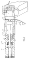
- the bolt-setting device shown in FIG. 1 contains a housing 1 with an axially aligned part that receives the setting mechanism and a laterally attached handle 2.
- the handle 2 is designed as a bow handle. It contains a deduction 3.
- the housing 1 contains a cylindrical interior, in which a driving piston guide 4 is guided so as to be displaceable in the axial direction by a certain amount.
- the displaceability of the driving piston guide 4 serves to secure the device against misuse and the supply of cartridges.
- a driving piston 5 is arranged axially displaceably in the driving piston guide 4.
- the driving piston 5 contains one here disc-like part 6 with an enlarged diameter, which rests on the inside 7 of the cylindrical inner opening of the driving piston guide 4.
- the disk part 6 is arranged at the end of a cylindrical driving piston shaft 8.
- such a stepped piston can also be used without the step, ie without the disk-like, enlarged part.
- a bolt guide 9 in the form of a guide sleeve is arranged in the housing 1 on the front end region receiving the fastening means.
- This pin guide 9 contains a first cylindrical part which engages in the interior of the piston guide 4 and a second part which extends outwards through the end face 10 of the housing. Both parts, which have different diameters in the exemplary embodiment shown, but which is not necessary, are separated from one another by a radially projecting flange 11.
- the flange 11 is arranged in an annular groove 12 in the housing 1, the axial extent of which is greater than the thickness of the flange 11. As a result, the bolt guide 9 can be displaced in the housing by a certain distance.
- the free end face of the driving piston guide 4 bears against the end face 13 of the flange 11 facing away from the end face 10 of the housing 1.
- the inner opening 14 of the bolt guide 9 serves to receive and hold the fastening element 15, for example in the form of a nail or bolt.
- a ring element 16 made of elastomer material is arranged, the outside diameter of which is approximately equal to the inside diameter of the piston guide 4 and the inside diameter of which is somewhat larger than the outside diameter of the pin part 8 of the driving piston 5.
- This ring element 16, which can also be firmly connected to the pin guide 9, serves as a brake for the driving piston 5.
- the pin guide 9 contains a damping element 18 which continues the pin guide 9 and which is likewise produced as a ring element from an elastomer material and is firmly connected to the pin guide 9, for example by vulcanization on the end face.
- the pin guide 9 forms a single component together with the damping element 18.
- the device is operated as follows. After inserting the fastening means 15 into the bolt guide 9, the device is pressed against the material 17 to be fastened by the user. This pressure is transferred to the pin guide 9, which pushes the piston guide 4 into the device with the aid of the flange 11. As a result, the cartridge chamber 19 arrives in the rear part of the driving piston guide 4 in a manner not to be described in more detail via the propellant charge powder cartridge which is ready, and the firing pin spring is tensioned. After trigger 3 is triggered, the propellant charge is fired and the propelling piston 5 is moved forward. The fastening means 15 is thereby driven into the substrate 20 through the material 17 to be fastened.
- the driving piston 5 runs onto the ring element 16 which acts as a piston brake. This is compressed and thereby expands radially, so that it is axially fixed relatively fixed in the piston guide 4. The residual energy is thereby transferred to the piston guide 4 and possibly the housing 1. Due to the buffer stroke and a partial axial movement of the piston guide 4, part of the kinetic energy is transferred to the pin guide 9. This residual energy of the pin guide 9 is then absorbed by the damping element 18.
- Fig. 1 shows the axial position of the bolt guide 9 in a state in which can not be fired. At the moment firing, however, the pin guide 9 is shifted to the right so that the damping element 18 is located within the front part of the housing. When the damping element 18 is acted upon axially, the latter is also expanded radially, which leads to a jamming between the pin guide 9 and the housing 1 which also acts in the axial direction.
- FIG. 2 shows an embodiment of the pin guide 9 in which the damping element 18 as a ring element 21 between two parts of the pin guide 9, which is otherwise constructed in the same way is arranged.
- the ring element 21 is matched to the bolt guide 9 with its outer and inner dimensions.
- FIG. 3 again shows a side view of the driving piston 5 with its shaft 8 in the same arrangement as in FIG. 1.
- the ring element 16 which acts as a piston brake and is made of elastomer material, is also shown in the same position as in FIG. 1.
- the sleeve 22 is designed such that it can elastically deform in the space between the disk part 6 and the braking element 16 in the event of axial compression, which is caused by the movement of the driving piston 5, whereby it remains enclosed within a closed space during this deformation . Due to the elastic deformation, it develops restoring forces which, after the setting process has taken place, return the driving piston 5 in the piston guide 4 to its starting position shown in FIG. 1.
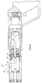
- Fig. 4 shows a partial longitudinal section through a further embodiment. While in the embodiment according to FIG. 1 the piston guide 4 is designed to be displaceable in the housing 1, in the embodiment according to FIG. 4 a one-piece housing 1 is shown with a piston guide 23 formed by a cylindrical interior. To manufacture the housing 1 would have to be constructed from several parts, but this is not shown for reasons of simplification.
- a piston guide 23 formed by a cylindrical interior. To manufacture the housing 1 would have to be constructed from several parts, but this is not shown for reasons of simplification.
- the braking element 16 which is designed as a ring element, is arranged on the side of the flange 24 facing the driving piston 5. It can be displaceable in the piston guide 23 both with the driving piston 5 and also attached to the flange 24 itself or only in contact. The braking effect of this ring element 16 then takes place simply by bearing on the side surface of the flange 24.
- the free end of the housing 1 is also provided with a damping element 26, which corresponds to the damping element 18 of the pin guide 9.
- a damping element 26a is attached analogously to the front, which additionally dampens the residual energy transmitted via the flange 24 onto the pin guide 9 when the piston 5 strikes the brake element 16.
- FIG. 5 likewise shows in simplified form an embodiment in which the driving piston 5 is connected to a piston-shaped guide cylinder 29 via, for example, a sleeve-shaped connecting link 28.
- This guide piston 29 contains two diametrically arranged lugs 30 which each protrude outward through a housing slot 31.
- a spring 32 for example made of elastomer material, is fastened to the regions of the lugs 30 lying outside the housing 1, the other end of which is connected to a lug 33 fixed to the housing.
- the spring 32 which is only indicated, is designed as a tension spring in this case.
- the distance between the driving piston 5 and the guide piston 29 is chosen so that the driving piston 5 only reaches the slot 31 at the end of its movement, so that the driving gas can only escape there.
- the driving piston 5 is provided with a rod 34 on the side opposite the piston guide 23, at the end of which a piston-shaped guide cylinder 35 is attached.
- the rod 34 extends through an opening in a transverse wall 36.
- the transverse wall 36 delimits a cavity 37 in which both the braking element 16 and a return spring 38 are accommodated.
- the braking element 16 is arranged directly on the transverse wall 36, while the return spring 38 is attached in the remaining space.
- the braking element 16 can of course also be arranged in the front space according to FIG. 1, ie between the front of the piston and the pin guide, so that there is only the return spring in the rear cavity 37.
- the propellant charge cartridge is also introduced with radial openings 39, but could also be done in a different way.
- the embodiment according to FIG. 6 is particularly suitable for a cartridge feed by means of a rotary movement of the housing 1, which can be achieved by the axial movement via a control cam, similar to a ballpoint pen mechanism.
- FIG. 7 shows schematically and in a ready-to-fire (cocked) state an embodiment in which, for example, the arrangement of FIG. 4 can be used.
- the bolt-actuating device contains a two-part housing, consisting of a holding part 40 and a front housing part 41 which is axially displaceable relative thereto, which at the same time corresponds to the piston guide 4 of the previous embodiment according to FIG. 1.
- the bolt guide 9 is arranged in the front housing part 41 and the piston guide 23 is formed.
- a compression spring acting between a shoulder 42 of the mounting part and a shoulder 43 of the front part ensures that the housing front part 41 is in an extended state when it is not pressed against the ground.
- the cartridge abutment 44 on which the cartridge is supported when the front housing part 41 is pressed, is located in the holding part 40.
- the indicated cartridges 45 are pushed into the cartridge bearing 45a at the end of the front housing part 41 in order to be fired there.
- the cartridge bearing 44 is guided by a punch 46, on the free end of which a pressure plate 47 is arranged. Between the pressure plate 47 and the end wall 48, the Limited interior space of the holding part 40, a further damping element 49 is arranged.
- the damping element 49 is a relatively hard elastomeric material since the cartridge abutment 44 should not yield when the front housing part 41 and / or the bolt guide 9 is pressed on to tension the device.
- the damping element 49 serves to dampen the recoil occurring during the setting process and thereby relieves the operator of the device.
- the inward-facing flange 24 present in the embodiment according to FIGS. 4 and 7 is designed here as a loose screw-in element 24 ', the housing front part 41 being constructed from two parts which can be screwed together.
- the piston shaft 8 in the embodiment according to FIG. 8 only extends approximately to the outside of the flange 24.
- a second drive piston 51 which has a disk-shaped guide collar 52.
- a damping element 53 is arranged, which brakes the second drive piston 51 on its guide collar 52. While in the previous embodiments two dampings arranged one behind the other in time and space occur, namely on the one hand that for braking the driving piston and on the other hand the resulting axial movement of the entire movable system consisting of the housing and / or the pin guide, in the embodiment according to FIG. 8 three such damping connected in series, the braking of the drive piston 5 and the second drive piston 51 can also occur simultaneously.
- the shaft 8 of the driving piston 5 can be connected to the additional driving piston 51 by means of a bayonet catch or some other device.
- FIG. 9 shows a ring 54 made of elastomer material as the return spring, which is subjected to tension.
- a hook 55 is attached to the housing of the bolt-actuating device, while a second hook 56 is connected to the driving piston 5. This could happen, for example, as shown in FIG. 5.
- this ring is then subjected to tension.
- the elastomer ring 54 could also be arranged in the rear cavity 37 of the embodiment according to FIG. 6.
- FIG. 10 shows a spring element 57, which is arranged around the shaft 8 of the driving piston 5, similarly to the embodiment according to FIG. 3. It is made up of a large number of individual layers 58, each of which consists of elastomer material and can be loose or connected to one another. For example by gluing or vulcanizing. Due to the large number of loose or interconnected layers, better dimensional stability can be achieved. It is also possible for the layers to consist of different materials and / or for the spring elements to be conical or double-conical.
- FIGS. 11 and 12. 11 is again only to be understood schematically.
- the element shown in FIG. 11 contains individual disks 59 which have the same diameter for better guidance like the driving piston 5 and form a kind of chamber. In between are the actual spring elements, the elastomer rings 60.
- the elastomer rings 60 can also be arranged in shallow indentations, or small projections could be provided on the surfaces of the disks 59 in order to prevent the elastomer rings 60 from being completely pressed flat (blocking) when the device is compressed.
- rings 61 instead of or in addition to the elastomer rings 60 which are round in cross section, rings 61 with a different cross section and different material could also be present. 11, the elastomer rings 60, 61, which are relatively easy to compress, assume the role of the return spring.
- This element can be arranged both in the working space in front of the driving piston 5 and behind it in the cavity as in the embodiment according to FIG. 6.
- a bolt-setting tool of the design according to the invention can be provided without problems with a nail magazine on the front, so that an automatic and quick setting of the fastening means is then ensured.
Landscapes
- Engineering & Computer Science (AREA)
- Chemical & Material Sciences (AREA)
- Combustion & Propulsion (AREA)
- Mechanical Engineering (AREA)
- Portable Nailing Machines And Staplers (AREA)
- Braking Arrangements (AREA)
- Details Of Spanners, Wrenches, And Screw Drivers And Accessories (AREA)
- Diaphragms And Bellows (AREA)
- Gripping Jigs, Holding Jigs, And Positioning Jigs (AREA)
- Dowels (AREA)
- Vibration Dampers (AREA)
- Surgical Instruments (AREA)
- Fluid-Damping Devices (AREA)
- Vehicle Body Suspensions (AREA)
- Forging (AREA)
- Braking Systems And Boosters (AREA)
Priority Applications (1)
| Application Number | Priority Date | Filing Date | Title |
|---|---|---|---|
| EP99124281A EP0995552B1 (fr) | 1995-03-17 | 1996-03-09 | Appareil de scellement de chevilles |
Applications Claiming Priority (2)
| Application Number | Priority Date | Filing Date | Title |
|---|---|---|---|
| DE19509763A DE19509763A1 (de) | 1995-03-17 | 1995-03-17 | Bolzensetzgerät |
| DE19509763 | 1995-03-17 |
Related Child Applications (1)
| Application Number | Title | Priority Date | Filing Date |
|---|---|---|---|
| EP99124281A Division EP0995552B1 (fr) | 1995-03-17 | 1996-03-09 | Appareil de scellement de chevilles |
Publications (2)
| Publication Number | Publication Date |
|---|---|
| EP0732178A1 true EP0732178A1 (fr) | 1996-09-18 |
| EP0732178B1 EP0732178B1 (fr) | 2000-06-07 |
Family
ID=7756986
Family Applications (2)
| Application Number | Title | Priority Date | Filing Date |
|---|---|---|---|
| EP99124281A Expired - Lifetime EP0995552B1 (fr) | 1995-03-17 | 1996-03-09 | Appareil de scellement de chevilles |
| EP96103717A Expired - Lifetime EP0732178B1 (fr) | 1995-03-17 | 1996-03-09 | Outil de scellement de chevilles |
Family Applications Before (1)
| Application Number | Title | Priority Date | Filing Date |
|---|---|---|---|
| EP99124281A Expired - Lifetime EP0995552B1 (fr) | 1995-03-17 | 1996-03-09 | Appareil de scellement de chevilles |
Country Status (7)
| Country | Link |
|---|---|
| EP (2) | EP0995552B1 (fr) |
| AT (2) | ATE361179T1 (fr) |
| DE (3) | DE19509763A1 (fr) |
| DK (1) | DK0732178T3 (fr) |
| ES (2) | ES2284233T3 (fr) |
| GR (1) | GR3033960T3 (fr) |
| PT (1) | PT732178E (fr) |
Cited By (11)
| Publication number | Priority date | Publication date | Assignee | Title |
|---|---|---|---|---|
| EP0826464A1 (fr) * | 1996-09-02 | 1998-03-04 | HILTI Aktiengesellschaft | Outil de scellement actionné par poudre avec des moyens de rappel du piston |
| EP0830920A1 (fr) * | 1996-09-19 | 1998-03-25 | Adolf Würth GmbH & Co. KG | Outil de scellement et un ressort de rappel pour cet outil |
| WO1998023413A1 (fr) * | 1996-11-24 | 1998-06-04 | Gerd Kellner | Systeme de mise en place de boulons |
| EP0881042A1 (fr) * | 1997-05-30 | 1998-12-02 | HILTI Aktiengesellschaft | Outil de scellement avec un dispositif de retour pour la piston d'entraínement |
| WO1999029472A1 (fr) * | 1997-12-04 | 1999-06-17 | Kellner, Gerd | Appareil pour placer un element de fixation dans une base d'appui et utilisation dudit appareil |
| FR2772298A1 (fr) * | 1997-12-15 | 1999-06-18 | Hilti Ag | Outil de scellement actionne par des gaz a haute pression |
| WO1999036230A1 (fr) * | 1998-01-19 | 1999-07-22 | Cagodzinski Marek | Outil electrique a piston avec retour automatique du piston |
| DE19824389A1 (de) * | 1998-05-30 | 1999-12-02 | Adolf Wuerth Gmbh & Co Kg | Bolzenschubgerät |
| CN100387404C (zh) * | 2002-11-04 | 2008-05-14 | 希尔蒂股份公司 | 用燃料工作的安装工具 |
| EP2133178A1 (fr) * | 2008-06-11 | 2009-12-16 | Black & Decker, Inc. | Ensemble de butée résilient pour outil d'impact |
| WO2023135041A1 (fr) * | 2022-01-14 | 2023-07-20 | Fischerwerke Gmbh & Co. Kg | Cloueur à poudre pour enfoncer un élément de fixation dans un support |
Families Citing this family (3)
| Publication number | Priority date | Publication date | Assignee | Title |
|---|---|---|---|---|
| RU2224071C2 (ru) * | 1998-04-14 | 2004-02-20 | АДОЛЬФ ВЮРТ ГмбХ унд Ко. КГ | Строительно-монтажный пистолет и пружина для него |
| DE10358576A1 (de) * | 2003-12-15 | 2005-07-28 | Hilti Ag | Brennkraftbetriebenes Setzgerät |
| DE102008000909A1 (de) | 2008-04-01 | 2009-10-08 | Hilti Aktiengesellschaft | Brennkraftbetriebenes Setzgerät |
Citations (14)
| Publication number | Priority date | Publication date | Assignee | Title |
|---|---|---|---|---|
| CH318934A (de) * | 1952-12-29 | 1957-01-31 | Anstalt Fuer Montage Technik | Schiessvorrichtung für Verankerungsbolzen |
| US3126630A (en) * | 1964-03-31 | T catlin | ||
| US3249279A (en) * | 1963-09-04 | 1966-05-03 | Behrend Herbert | Bolt and charge operated tool for driving in a bolt |
| US3331546A (en) * | 1965-06-01 | 1967-07-18 | Olin Mathieson | Piston return and buffer system |
| US3566978A (en) * | 1968-01-29 | 1971-03-02 | Hilti Ag | Apparatus for driving anchoring elements for a predetermined depth of penetration |
| DE2727639A1 (de) * | 1977-06-20 | 1979-01-04 | Hilti Ag | Pulverkraftbetriebenes bolzensetzgeraet |
| US4204622A (en) * | 1975-05-23 | 1980-05-27 | Cunningham James D | Electric impact tool |
| DE2850273A1 (de) * | 1978-11-20 | 1980-05-29 | Hilti Ag | Pulverkraftbetriebenes bolzensetzgeraet |
| AU548929B2 (en) * | 1982-07-27 | 1986-01-09 | Gareth J. Smith | Dimpling fastener driving tool |
| US4746047A (en) * | 1987-01-28 | 1988-05-24 | Moskovskoe Naucho-Rpoizvodstvennoe Objedinenie Po Mekhanizirovannomu Stroitelnomu Instrumentu I Otdelchnym Mashinam | Hand-held fastening element driving tool |
| EP0274957A1 (fr) * | 1986-12-23 | 1988-07-20 | Societe De Prospection Et D'inventions Techniques Spit | Appareil de scellement à tir indirect |
| DE8915510U1 (de) * | 1989-03-22 | 1990-08-30 | Kellner, Gerd, Dr.-Ing., 7230 Schramberg | Bolzensetzgerät |
| EP0410928A1 (fr) * | 1989-07-26 | 1991-01-30 | HILTI Aktiengesellschaft | Pistolet de scellement actionné par explosion de poudre |
| US5205457A (en) * | 1992-01-06 | 1993-04-27 | Blomquist Jr Roy A | Driving tool and method |
Family Cites Families (6)
| Publication number | Priority date | Publication date | Assignee | Title |
|---|---|---|---|---|
| US2354958A (en) * | 1943-05-29 | 1944-08-01 | Hydraulic Brake Co | Diaphragm pump |
| US3301335A (en) * | 1964-04-20 | 1967-01-31 | Thomas E Snelling | Energy absorbing structure |
| FR1600417A (fr) * | 1968-08-05 | 1970-07-27 | ||
| FR2109090A5 (fr) * | 1970-09-16 | 1972-05-26 | Reymond Michel | |
| DE7622745U1 (de) * | 1976-07-19 | 1978-04-27 | Hilti Ag, Schaan (Liechtenstein) | Pulverkraftbetriebenes bolzensetzgeraet mit einer abfangvorrichtung fuer den treibkolben |
| US4442757A (en) * | 1981-08-24 | 1984-04-17 | Baker Cac, Inc. | Fluid pressure actuator having bias element immersed in non-corrosive environment |
-
1995
- 1995-03-17 DE DE19509763A patent/DE19509763A1/de not_active Withdrawn
-
1996
- 1996-03-09 EP EP99124281A patent/EP0995552B1/fr not_active Expired - Lifetime
- 1996-03-09 DK DK96103717T patent/DK0732178T3/da active
- 1996-03-09 AT AT99124281T patent/ATE361179T1/de not_active IP Right Cessation
- 1996-03-09 DE DE59611428T patent/DE59611428D1/de not_active Expired - Lifetime
- 1996-03-09 ES ES99124281T patent/ES2284233T3/es not_active Expired - Lifetime
- 1996-03-09 DE DE59605376T patent/DE59605376D1/de not_active Expired - Lifetime
- 1996-03-09 ES ES96103717T patent/ES2149396T3/es not_active Expired - Lifetime
- 1996-03-09 AT AT96103717T patent/ATE193668T1/de not_active IP Right Cessation
- 1996-03-09 EP EP96103717A patent/EP0732178B1/fr not_active Expired - Lifetime
- 1996-03-09 PT PT96103717T patent/PT732178E/pt unknown
-
2000
- 2000-07-17 GR GR20000401645T patent/GR3033960T3/el not_active IP Right Cessation
Patent Citations (14)
| Publication number | Priority date | Publication date | Assignee | Title |
|---|---|---|---|---|
| US3126630A (en) * | 1964-03-31 | T catlin | ||
| CH318934A (de) * | 1952-12-29 | 1957-01-31 | Anstalt Fuer Montage Technik | Schiessvorrichtung für Verankerungsbolzen |
| US3249279A (en) * | 1963-09-04 | 1966-05-03 | Behrend Herbert | Bolt and charge operated tool for driving in a bolt |
| US3331546A (en) * | 1965-06-01 | 1967-07-18 | Olin Mathieson | Piston return and buffer system |
| US3566978A (en) * | 1968-01-29 | 1971-03-02 | Hilti Ag | Apparatus for driving anchoring elements for a predetermined depth of penetration |
| US4204622A (en) * | 1975-05-23 | 1980-05-27 | Cunningham James D | Electric impact tool |
| DE2727639A1 (de) * | 1977-06-20 | 1979-01-04 | Hilti Ag | Pulverkraftbetriebenes bolzensetzgeraet |
| DE2850273A1 (de) * | 1978-11-20 | 1980-05-29 | Hilti Ag | Pulverkraftbetriebenes bolzensetzgeraet |
| AU548929B2 (en) * | 1982-07-27 | 1986-01-09 | Gareth J. Smith | Dimpling fastener driving tool |
| EP0274957A1 (fr) * | 1986-12-23 | 1988-07-20 | Societe De Prospection Et D'inventions Techniques Spit | Appareil de scellement à tir indirect |
| US4746047A (en) * | 1987-01-28 | 1988-05-24 | Moskovskoe Naucho-Rpoizvodstvennoe Objedinenie Po Mekhanizirovannomu Stroitelnomu Instrumentu I Otdelchnym Mashinam | Hand-held fastening element driving tool |
| DE8915510U1 (de) * | 1989-03-22 | 1990-08-30 | Kellner, Gerd, Dr.-Ing., 7230 Schramberg | Bolzensetzgerät |
| EP0410928A1 (fr) * | 1989-07-26 | 1991-01-30 | HILTI Aktiengesellschaft | Pistolet de scellement actionné par explosion de poudre |
| US5205457A (en) * | 1992-01-06 | 1993-04-27 | Blomquist Jr Roy A | Driving tool and method |
Cited By (20)
| Publication number | Priority date | Publication date | Assignee | Title |
|---|---|---|---|---|
| US5901894A (en) * | 1996-09-02 | 1999-05-11 | Hilti Aktiengesellschaft | High pressure gas operated setting tool |
| EP0826464A1 (fr) * | 1996-09-02 | 1998-03-04 | HILTI Aktiengesellschaft | Outil de scellement actionné par poudre avec des moyens de rappel du piston |
| US6182881B1 (en) | 1996-09-19 | 2001-02-06 | Adolf Wurth Gmbh & Co. Kg | Stud driver and spring therefor |
| EP0830920A1 (fr) * | 1996-09-19 | 1998-03-25 | Adolf Würth GmbH & Co. KG | Outil de scellement et un ressort de rappel pour cet outil |
| CN1068818C (zh) * | 1996-09-19 | 2001-07-25 | 阿道夫维尔特股份有限公司 | 螺栓驱动器及其弹簧 |
| WO1998023413A1 (fr) * | 1996-11-24 | 1998-06-04 | Gerd Kellner | Systeme de mise en place de boulons |
| EP0881042A1 (fr) * | 1997-05-30 | 1998-12-02 | HILTI Aktiengesellschaft | Outil de scellement avec un dispositif de retour pour la piston d'entraínement |
| CZ296853B6 (cs) * | 1997-12-04 | 2006-07-12 | Nástroj k zatloukání upevnovacího prvku | |
| AU732265B2 (en) * | 1997-12-04 | 2001-04-12 | Kellner, Gerd | Apparatus for emplacing a fastening element into a placement base, and use of the apparatus |
| US6457624B1 (en) | 1997-12-04 | 2002-10-01 | Futurtec Ag | Device for driving a fastening element into a base and use of said device |
| WO1999029472A1 (fr) * | 1997-12-04 | 1999-06-17 | Kellner, Gerd | Appareil pour placer un element de fixation dans une base d'appui et utilisation dudit appareil |
| FR2772298A1 (fr) * | 1997-12-15 | 1999-06-18 | Hilti Ag | Outil de scellement actionne par des gaz a haute pression |
| WO1999036230A1 (fr) * | 1998-01-19 | 1999-07-22 | Cagodzinski Marek | Outil electrique a piston avec retour automatique du piston |
| DE19824389A1 (de) * | 1998-05-30 | 1999-12-02 | Adolf Wuerth Gmbh & Co Kg | Bolzenschubgerät |
| EP0962289A2 (fr) | 1998-05-30 | 1999-12-08 | Adolf Würth GmbH & Co. KG | Outil de scellement de chevilles |
| EP0962289A3 (fr) * | 1998-05-30 | 2000-11-08 | Adolf Würth GmbH & Co. KG | Outil de scellement de chevilles |
| CN100387404C (zh) * | 2002-11-04 | 2008-05-14 | 希尔蒂股份公司 | 用燃料工作的安装工具 |
| EP2133178A1 (fr) * | 2008-06-11 | 2009-12-16 | Black & Decker, Inc. | Ensemble de butée résilient pour outil d'impact |
| US8104547B2 (en) | 2008-06-11 | 2012-01-31 | Black & Decker Inc. | Resilient stop assembly for impact tool |
| WO2023135041A1 (fr) * | 2022-01-14 | 2023-07-20 | Fischerwerke Gmbh & Co. Kg | Cloueur à poudre pour enfoncer un élément de fixation dans un support |
Also Published As
| Publication number | Publication date |
|---|---|
| EP0995552A2 (fr) | 2000-04-26 |
| ATE193668T1 (de) | 2000-06-15 |
| DE19509763A1 (de) | 1996-09-19 |
| GR3033960T3 (en) | 2000-11-30 |
| ES2149396T3 (es) | 2000-11-01 |
| PT732178E (pt) | 2000-09-29 |
| DK0732178T3 (da) | 2000-10-30 |
| ATE361179T1 (de) | 2007-05-15 |
| ES2284233T3 (es) | 2007-11-01 |
| DE59605376D1 (de) | 2000-07-13 |
| EP0732178B1 (fr) | 2000-06-07 |
| EP0995552A3 (fr) | 2000-11-08 |
| DE59611428D1 (de) | 2007-06-14 |
| EP0995552B1 (fr) | 2007-05-02 |
Similar Documents
| Publication | Publication Date | Title |
|---|---|---|
| DE69719590T2 (de) | Verbrennungsbetriebenes Werkzeug mit Kolbenhalter- und Stabilisierungsanordnung | |
| EP1035950B1 (fr) | Appareil pour placer un element de fixation dans une base d'appui et utilisation dudit appareil | |
| EP0732178B1 (fr) | Outil de scellement de chevilles | |
| DE19755730A1 (de) | Bolzensetzgerät | |
| DE1603918C3 (de) | Treibkolbenpuffer und TreibkolbenrückfUhrfeder an einem Eintreibwerkzeug | |
| DE3515244C2 (fr) | ||
| EP0558963A2 (fr) | Dispositif tendeur linéaire pour un système de retenue dans un véhicule | |
| EP0805002B1 (fr) | Appareil de scellement de chevilles actionné par la poudre | |
| DE3422669C2 (de) | Nadelhammer mit vorrichtung zum ausgleich des nadelhubes bei der bearbeitung von unebenen werkstueckoberflaechen | |
| DE1478822A1 (de) | Bolzensetzgeraet | |
| EP1088627B1 (fr) | Outil de scellement de chevilles ou similaires sur élément de construction | |
| EP0826464A1 (fr) | Outil de scellement actionné par poudre avec des moyens de rappel du piston | |
| EP0830920B1 (fr) | Outil de scellement et un ressort de rappel pour cet outil | |
| EP0805003B1 (fr) | Appareil de scellement de chevilles actionné par la poudre | |
| DE10259817B4 (de) | Brennkraftbetriebenes Setzgerät für Befestigungselemente | |
| DE3930592A1 (de) | Bolzensetzgeraet | |
| DE102005000106B4 (de) | Setzgerät | |
| DE10105881A1 (de) | Kolbenhalterung | |
| DE102012217686A1 (de) | Geradezug-Repetiergewehr mit einem Verschlussmechanismus | |
| EP0962289B1 (fr) | Outil de scellement de chevilles | |
| DE2927507C2 (de) | Bolzenschußapparat | |
| DE3923612A1 (de) | Pulverkraftbetriebenes bolzensetzgeraet | |
| DE3739448A1 (de) | Automatische feuerwaffe | |
| AT222694B (de) | Einrichtung zur Reibungsdämpfung von Eisenbahnhülsenpuffern | |
| DE2954538C2 (de) | Bolzenschußapparat zur Betäubung von Schlachtvieh |
Legal Events
| Date | Code | Title | Description |
|---|---|---|---|
| PUAI | Public reference made under article 153(3) epc to a published international application that has entered the european phase |
Free format text: ORIGINAL CODE: 0009012 |
|
| AK | Designated contracting states |
Kind code of ref document: A1 Designated state(s): AT BE CH DE DK ES FI FR GB GR IE IT LI LU MC NL PT SE |
|
| 17P | Request for examination filed |
Effective date: 19961110 |
|
| 17Q | First examination report despatched |
Effective date: 19980721 |
|
| GRAG | Despatch of communication of intention to grant |
Free format text: ORIGINAL CODE: EPIDOS AGRA |
|
| GRAG | Despatch of communication of intention to grant |
Free format text: ORIGINAL CODE: EPIDOS AGRA |
|
| GRAH | Despatch of communication of intention to grant a patent |
Free format text: ORIGINAL CODE: EPIDOS IGRA |
|
| GRAH | Despatch of communication of intention to grant a patent |
Free format text: ORIGINAL CODE: EPIDOS IGRA |
|
| GRAA | (expected) grant |
Free format text: ORIGINAL CODE: 0009210 |
|
| AK | Designated contracting states |
Kind code of ref document: B1 Designated state(s): AT BE CH DE DK ES FI FR GB GR IE IT LI LU MC NL PT SE |
|
| REF | Corresponds to: |
Ref document number: 193668 Country of ref document: AT Date of ref document: 20000615 Kind code of ref document: T |
|
| REG | Reference to a national code |
Ref country code: CH Ref legal event code: NV Representative=s name: TROESCH SCHEIDEGGER WERNER AG Ref country code: CH Ref legal event code: EP |
|
| REG | Reference to a national code |
Ref country code: IE Ref legal event code: FG4D Free format text: GERMAN |
|
| REF | Corresponds to: |
Ref document number: 59605376 Country of ref document: DE Date of ref document: 20000713 |
|
| ITF | It: translation for a ep patent filed | ||
| GBT | Gb: translation of ep patent filed (gb section 77(6)(a)/1977) |
Effective date: 20000815 |
|
| ET | Fr: translation filed | ||
| REG | Reference to a national code |
Ref country code: PT Ref legal event code: SC4A Free format text: AVAILABILITY OF NATIONAL TRANSLATION Effective date: 20000628 |
|
| REG | Reference to a national code |
Ref country code: DK Ref legal event code: T3 |
|
| REG | Reference to a national code |
Ref country code: ES Ref legal event code: FG2A Ref document number: 2149396 Country of ref document: ES Kind code of ref document: T3 |
|
| PGFP | Annual fee paid to national office [announced via postgrant information from national office to epo] |
Ref country code: MC Payment date: 20010323 Year of fee payment: 6 |
|
| PGFP | Annual fee paid to national office [announced via postgrant information from national office to epo] |
Ref country code: LU Payment date: 20010327 Year of fee payment: 6 |
|
| PGFP | Annual fee paid to national office [announced via postgrant information from national office to epo] |
Ref country code: IE Payment date: 20010329 Year of fee payment: 6 |
|
| PLBE | No opposition filed within time limit |
Free format text: ORIGINAL CODE: 0009261 |
|
| STAA | Information on the status of an ep patent application or granted ep patent |
Free format text: STATUS: NO OPPOSITION FILED WITHIN TIME LIMIT |
|
| 26N | No opposition filed | ||
| REG | Reference to a national code |
Ref country code: GB Ref legal event code: IF02 |
|
| PG25 | Lapsed in a contracting state [announced via postgrant information from national office to epo] |
Ref country code: MC Free format text: LAPSE BECAUSE OF NON-PAYMENT OF DUE FEES Effective date: 20020309 Ref country code: LU Free format text: LAPSE BECAUSE OF NON-PAYMENT OF DUE FEES Effective date: 20020309 |
|
| PG25 | Lapsed in a contracting state [announced via postgrant information from national office to epo] |
Ref country code: IE Free format text: LAPSE BECAUSE OF NON-PAYMENT OF DUE FEES Effective date: 20020311 |
|
| REG | Reference to a national code |
Ref country code: IE Ref legal event code: MM4A |
|
| PGFP | Annual fee paid to national office [announced via postgrant information from national office to epo] |
Ref country code: GB Payment date: 20030224 Year of fee payment: 8 |
|
| PGFP | Annual fee paid to national office [announced via postgrant information from national office to epo] |
Ref country code: NL Payment date: 20030317 Year of fee payment: 8 |
|
| PGFP | Annual fee paid to national office [announced via postgrant information from national office to epo] |
Ref country code: FR Payment date: 20030318 Year of fee payment: 8 |
|
| PGFP | Annual fee paid to national office [announced via postgrant information from national office to epo] |
Ref country code: SE Payment date: 20030324 Year of fee payment: 8 Ref country code: FI Payment date: 20030324 Year of fee payment: 8 Ref country code: DK Payment date: 20030324 Year of fee payment: 8 |
|
| PGFP | Annual fee paid to national office [announced via postgrant information from national office to epo] |
Ref country code: GR Payment date: 20030327 Year of fee payment: 8 |
|
| PG25 | Lapsed in a contracting state [announced via postgrant information from national office to epo] |
Ref country code: GB Free format text: LAPSE BECAUSE OF NON-PAYMENT OF DUE FEES Effective date: 20040309 Ref country code: FI Free format text: LAPSE BECAUSE OF NON-PAYMENT OF DUE FEES Effective date: 20040309 |
|
| PG25 | Lapsed in a contracting state [announced via postgrant information from national office to epo] |
Ref country code: SE Free format text: LAPSE BECAUSE OF NON-PAYMENT OF DUE FEES Effective date: 20040310 |
|
| PG25 | Lapsed in a contracting state [announced via postgrant information from national office to epo] |
Ref country code: DK Free format text: LAPSE BECAUSE OF NON-PAYMENT OF DUE FEES Effective date: 20040331 |
|
| PG25 | Lapsed in a contracting state [announced via postgrant information from national office to epo] |
Ref country code: NL Free format text: LAPSE BECAUSE OF NON-PAYMENT OF DUE FEES Effective date: 20041001 |
|
| PG25 | Lapsed in a contracting state [announced via postgrant information from national office to epo] |
Ref country code: GR Free format text: LAPSE BECAUSE OF NON-PAYMENT OF DUE FEES Effective date: 20041006 |
|
| GBPC | Gb: european patent ceased through non-payment of renewal fee | ||
| EUG | Se: european patent has lapsed | ||
| PG25 | Lapsed in a contracting state [announced via postgrant information from national office to epo] |
Ref country code: FR Free format text: LAPSE BECAUSE OF NON-PAYMENT OF DUE FEES Effective date: 20041130 |
|
| NLV4 | Nl: lapsed or anulled due to non-payment of the annual fee |
Effective date: 20041001 |
|
| REG | Reference to a national code |
Ref country code: FR Ref legal event code: ST |
|
| PGFP | Annual fee paid to national office [announced via postgrant information from national office to epo] |
Ref country code: BE Payment date: 20050322 Year of fee payment: 10 |
|
| PGFP | Annual fee paid to national office [announced via postgrant information from national office to epo] |
Ref country code: PT Payment date: 20060309 Year of fee payment: 11 |
|
| PGFP | Annual fee paid to national office [announced via postgrant information from national office to epo] |
Ref country code: CH Payment date: 20060324 Year of fee payment: 11 Ref country code: AT Payment date: 20060324 Year of fee payment: 11 |
|
| PG25 | Lapsed in a contracting state [announced via postgrant information from national office to epo] |
Ref country code: BE Free format text: LAPSE BECAUSE OF NON-PAYMENT OF DUE FEES Effective date: 20060331 |
|
| PG25 | Lapsed in a contracting state [announced via postgrant information from national office to epo] |
Ref country code: PT Free format text: LAPSE BECAUSE OF NON-PAYMENT OF DUE FEES Effective date: 20070910 |
|
| REG | Reference to a national code |
Ref country code: PT Ref legal event code: MM4A Free format text: LAPSE DUE TO NON-PAYMENT OF FEES Effective date: 20070910 |
|
| REG | Reference to a national code |
Ref country code: CH Ref legal event code: PL |
|
| PG25 | Lapsed in a contracting state [announced via postgrant information from national office to epo] |
Ref country code: AT Free format text: LAPSE BECAUSE OF NON-PAYMENT OF DUE FEES Effective date: 20070309 |
|
| BERE | Be: lapsed |
Owner name: ADOLF *WURTH G.M.B.H. & CO. K.G. Effective date: 20060331 |
|
| PG25 | Lapsed in a contracting state [announced via postgrant information from national office to epo] |
Ref country code: LI Free format text: LAPSE BECAUSE OF NON-PAYMENT OF DUE FEES Effective date: 20070331 Ref country code: CH Free format text: LAPSE BECAUSE OF NON-PAYMENT OF DUE FEES Effective date: 20070331 |
|
| PGFP | Annual fee paid to national office [announced via postgrant information from national office to epo] |
Ref country code: ES Payment date: 20100326 Year of fee payment: 15 |
|
| PGFP | Annual fee paid to national office [announced via postgrant information from national office to epo] |
Ref country code: IT Payment date: 20100326 Year of fee payment: 15 Ref country code: DE Payment date: 20100324 Year of fee payment: 15 |
|
| PG25 | Lapsed in a contracting state [announced via postgrant information from national office to epo] |
Ref country code: DE Free format text: LAPSE BECAUSE OF NON-PAYMENT OF DUE FEES Effective date: 20111001 |
|
| REG | Reference to a national code |
Ref country code: DE Ref legal event code: R119 Ref document number: 59605376 Country of ref document: DE Effective date: 20111001 |
|
| PG25 | Lapsed in a contracting state [announced via postgrant information from national office to epo] |
Ref country code: IT Free format text: LAPSE BECAUSE OF NON-PAYMENT OF DUE FEES Effective date: 20110309 |
|
| REG | Reference to a national code |
Ref country code: ES Ref legal event code: FD2A Effective date: 20120424 |
|
| PG25 | Lapsed in a contracting state [announced via postgrant information from national office to epo] |
Ref country code: ES Free format text: LAPSE BECAUSE OF NON-PAYMENT OF DUE FEES Effective date: 20110310 |