EP0732513B1 - Verfahren zum aktiven Dämpfen globaler Strömungsoszillationen in abgelösten instabilen Strömungen und Vorrichtung zur Anwendung des Verfahrens - Google Patents
Verfahren zum aktiven Dämpfen globaler Strömungsoszillationen in abgelösten instabilen Strömungen und Vorrichtung zur Anwendung des Verfahrens Download PDFInfo
- Publication number
- EP0732513B1 EP0732513B1 EP95810167A EP95810167A EP0732513B1 EP 0732513 B1 EP0732513 B1 EP 0732513B1 EP 95810167 A EP95810167 A EP 95810167A EP 95810167 A EP95810167 A EP 95810167A EP 0732513 B1 EP0732513 B1 EP 0732513B1
- Authority
- EP
- European Patent Office
- Prior art keywords
- flow
- oscillation
- accordance
- oscillations
- global
- Prior art date
- Legal status (The legal status is an assumption and is not a legal conclusion. Google has not performed a legal analysis and makes no representation as to the accuracy of the status listed.)
- Expired - Lifetime
Links
- 230000010355 oscillation Effects 0.000 title claims description 183
- 238000000034 method Methods 0.000 title claims description 49
- 238000013016 damping Methods 0.000 title claims description 26
- 230000001447 compensatory effect Effects 0.000 claims description 54
- 238000000926 separation method Methods 0.000 claims description 46
- 230000005284 excitation Effects 0.000 claims description 18
- 230000003321 amplification Effects 0.000 claims description 11
- 238000003199 nucleic acid amplification method Methods 0.000 claims description 11
- 230000003044 adaptive effect Effects 0.000 claims description 8
- 238000001914 filtration Methods 0.000 claims description 3
- 238000012545 processing Methods 0.000 claims description 3
- 238000005259 measurement Methods 0.000 claims description 2
- 238000011156 evaluation Methods 0.000 claims 1
- 230000007246 mechanism Effects 0.000 description 9
- 238000001228 spectrum Methods 0.000 description 9
- 230000000694 effects Effects 0.000 description 8
- 238000001514 detection method Methods 0.000 description 7
- 238000007373 indentation Methods 0.000 description 6
- 230000008569 process Effects 0.000 description 5
- 238000005457 optimization Methods 0.000 description 4
- 238000010025 steaming Methods 0.000 description 4
- 238000012546 transfer Methods 0.000 description 4
- 230000002238 attenuated effect Effects 0.000 description 3
- 230000033228 biological regulation Effects 0.000 description 3
- 230000003993 interaction Effects 0.000 description 3
- 239000000463 material Substances 0.000 description 3
- 230000000737 periodic effect Effects 0.000 description 3
- 230000005855 radiation Effects 0.000 description 3
- 230000004044 response Effects 0.000 description 3
- 206010013710 Drug interaction Diseases 0.000 description 2
- 230000015572 biosynthetic process Effects 0.000 description 2
- 230000001419 dependent effect Effects 0.000 description 2
- 230000001687 destabilization Effects 0.000 description 2
- 239000007788 liquid Substances 0.000 description 2
- 238000002360 preparation method Methods 0.000 description 2
- 230000010349 pulsation Effects 0.000 description 2
- 230000002787 reinforcement Effects 0.000 description 2
- 230000003595 spectral effect Effects 0.000 description 2
- 238000011144 upstream manufacturing Methods 0.000 description 2
- 241001236093 Bulbophyllum maximum Species 0.000 description 1
- 241000687303 Polites vibex Species 0.000 description 1
- 238000013459 approach Methods 0.000 description 1
- 230000008901 benefit Effects 0.000 description 1
- 230000008859 change Effects 0.000 description 1
- 238000006243 chemical reaction Methods 0.000 description 1
- 239000000498 cooling water Substances 0.000 description 1
- 230000008878 coupling Effects 0.000 description 1
- 238000010168 coupling process Methods 0.000 description 1
- 238000005859 coupling reaction Methods 0.000 description 1
- 230000007423 decrease Effects 0.000 description 1
- 208000037265 diseases, disorders, signs and symptoms Diseases 0.000 description 1
- 208000035475 disorder Diseases 0.000 description 1
- 239000012530 fluid Substances 0.000 description 1
- 230000006872 improvement Effects 0.000 description 1
- 238000007689 inspection Methods 0.000 description 1
- 230000007257 malfunction Effects 0.000 description 1
- 238000004519 manufacturing process Methods 0.000 description 1
- 239000000203 mixture Substances 0.000 description 1
- 230000035699 permeability Effects 0.000 description 1
- 230000010363 phase shift Effects 0.000 description 1
- 230000001105 regulatory effect Effects 0.000 description 1
- 230000003014 reinforcing effect Effects 0.000 description 1
- 230000035945 sensitivity Effects 0.000 description 1
- 230000008054 signal transmission Effects 0.000 description 1
- 239000007787 solid Substances 0.000 description 1
- 230000006641 stabilisation Effects 0.000 description 1
- 238000011105 stabilization Methods 0.000 description 1
- 238000003786 synthesis reaction Methods 0.000 description 1
- 230000002123 temporal effect Effects 0.000 description 1
- 230000007704 transition Effects 0.000 description 1
- 230000001960 triggered effect Effects 0.000 description 1
- 208000029761 vertebral disease Diseases 0.000 description 1
Images




Classifications
-
- F—MECHANICAL ENGINEERING; LIGHTING; HEATING; WEAPONS; BLASTING
- F15—FLUID-PRESSURE ACTUATORS; HYDRAULICS OR PNEUMATICS IN GENERAL
- F15D—FLUID DYNAMICS, i.e. METHODS OR MEANS FOR INFLUENCING THE FLOW OF GASES OR LIQUIDS
- F15D1/00—Influencing flow of fluids
- F15D1/10—Influencing flow of fluids around bodies of solid material
- F15D1/12—Influencing flow of fluids around bodies of solid material by influencing the boundary layer
Definitions
- the initials are formed called flow oscillations from small disturbances an unstable layer near a peel point.
- a known sufficient condition for an unstable For example, layer is a turning point of the Velocity profile of the flow along a line orthogonal to the flow lines.
- Such an unstable one Layer is called shear layer.
- Currents with Multiple peel points can have multiple unstable layers who, each forming a source of eddies for themselves, collectively to a common 'global' Flow oscillations interact.
- This method is based on a special situation tailored to the presence of one acoustic resonator, whose frequency is based on that of radiated by the global flow oscillations acoustic waves is tuned and because of Interaction between the detached unstable flow and the acoustic wave for self-excitation specific global flow oscillations.
- This Concept is therefore not transferable from the approach Cases where global flow oscillations are excited are through completely different self-excitation mechanisms. For example, it is known that an obstacle is introduced into a detached unstable flow, the appearance of global flow oscillations can cause specific details of the generated vortices such as the frequency the emitted acoustic wave or the geometric Arrangement of vortices in succession relative to one another to each other from details such as B.
- inventive method is characterized by the features of claim 1 and the inventive Device for applying the method is by the Features of claim 11 characterized.
- the inventive method for global steaming Flow oscillations in a flowing medium in the Area of one of at least one interface replacing unstable flow is now the global oscillations with a sensor system and the flowing medium one with the signals of the Sensor system controlled compensatory oscillation in a separation zone of the detached unstable flow vomge ceremoniesgen.
- the invention contains Device a generator that the flowing medium compensatory oscillation in a separation zone of the detached unstable flow, and a Control system that evaluates the signals from the sensor system and regulates the compensatory oscillation so that the Amplitude of a given global oscillation by one predetermined factor is damped.
- the method according to the invention consequently consists in using Help capture an existing global Flow oscillation using a sensor system approximate for a given area of the separation zone to identify a perturbation that the observed Flow oscillation would result, and this the flow in the given area of the separation zone in phase opposition and possibly with a weakened amplitude, d. H.
- global flow oscillations unite Representing a periodic process allows the recording a flow oscillation at a given time Determination of a compensatory disturbance which, in phase of the flow in a given range of Peeling zone imprinted, only the next or one of the can dampen the following vortex formation.
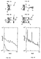
- FIG. 1 shows examples of flow systems that form different global flow oscillations can, and the associated for each flow system Frequency spectrum of the signals P of a pressure sensor 13, the is intended to be at a point in the range of one detached unstable flow global To detect flow oscillations without the flow to influence itself significantly.
- These examples serve as a starting point for a description of how it works of the inventive method and for the description of Embodiments of devices for its use.
- FIG. 1A-D shows 4 flow systems, each of which same source for a detached unstable flow 10 have a slot 9 of width h that any flowing medium, e.g. B. a liquid, a gas or a Gas-liquid mixture, with the density ⁇ of Flow velocity V crosses.
- the flow systems are each perpendicular in cross section through the slot 9 shown, d. H.
- the slot 9 is defined by two Limiting elements 9a, 9b perpendicular to the paper plane. It it is also assumed that the slot width h is very small is opposite the height of the slot and that the cross sections shown in the central region of the Slot are located where the flow conditions in the vertical direction are considered to be invariant can.
- the slot width h is very small is opposite the height of the slot and that the cross sections shown in the central region of the Slot are located where the flow conditions in the vertical direction are considered to be invariant can.
- a condition for self-excitement of Flow oscillations occur when downstream after detachment, an obstacle to the further course the flow influences as in the arrangements in FIG. 1B-D.
- the narrow-band maxima represent pressure pulsations, the amplitudes of which are a measure for the intensities of global flow oscillations are.
- the frequencies f and die Intensity of flow oscillations other than that Flow velocity V from the geometric arrangement of the obstacle with respect to slot 9 (FIG. 1B: Gap 7; FIG. 1C: wedge 14; FIG. 1D: gap 8 with Side walls).
- Flow oscillations necessary for the implementation of the The method according to the invention is relevant, but not the Frequency spectra of a pressure sensor can be taken is the spatial arrangement of the one after the other Vortex viewed at a given time. To a given time can under different Conditions generated a different vortex have spatial geometry.
- the in FIG. 1 shown Flow systems have e.g. B. 2 transfer points, of which each the edge point one downstream extending unstable layer form.
- vertebrae can do more or less simultaneously (symmetrical modes, e.g. vortex 6a, 6b in FIG. 1D) or in phase opposition, d. H. in same Time intervals alternately either at the transfer point 11 or at separation point 12 (antisymmetric modes, e.g. vortex 5a, 5b in FIG. 1C) arise, the perfectly symmetrical or perfectly antisymmetric flow oscillations usually have the greatest intensity.
- This temporal Processes must be in a phase-appropriate synthesis of a compensatory oscillation to dampen the global Flow oscillation are taken into account.
- FIG. 2 is the one causing the flow oscillation Obstacle, the wedge 14, symmetrical to the perpendicular the slot 9, the x-axis.
- This is an example of one antisymmetric flow oscillation.
- the essential Parameters with regard to the active damping of the Flow oscillations are recorded, their frequency and a measure of their intensity.
- Preferred sensors for detecting the frequency and the The intensity of the flow oscillation is a pressure sensor or a sensor for measuring the flow velocity.
- Preferred positions for such sensors are points in the flowing medium, on the one hand the sensor itself influenced the flow only little and not itself to the The trigger of flow oscillations. Are on the other side to optimize sensor sensitivity points in the Area of influence of the vertebrae with the greatest expansion or Points close to the flow oscillation causing obstacle advantageous.
- the sensor can also be built into the obstacle.
- An alternative sensor for detecting the frequency and the Intensity of flow oscillation is a force sensor, which detects the force that the flow has on the Obstacle 14 exercises.
- Suitable sensors are commercially available: as Pressure sensor is suitable, for example, as a microphone Sensor for measuring the flow rate Hot wire instrument, strain gauges as force sensors or piezoelectric or piezoresistive sensors.
- FIG. 3 An efficient alternative to this acoustic method to generate a compensatory oscillation shows FIG. 3.
- the stabilization is a unstable layer achieved by an oscillation of the corresponding separation point.
- This oscillation can be caused by a mechanical movement of a Element of the interface from which the unstable Current takes over.
- Such a tilt leads to a shift the separation points perpendicular to the boundary elements and thus to a lateral deflection of an unstable one Layer across the current. This deflection is by means of Control signals of the sensor system so that a malfunction the unstable layer near a peel point is compensated.
- the amplitudes and phases of the two excitation sources 17, 18 are controlled by a signal that results from the signal of the sensor 13 by frequency filtering and / or amplification and / or phase shift.
- the signals from sensor 13 are fed to a frequency filter 25 (24). This frequency filtering is optional and only serves to suppress noise.
- the frequency-filtered signal is fed via line 27 to an amplifier element 29 and from there via line 31 to excitation source 18. This signal determines the amplitude and phase of the excitation source 31. Accordingly, the amplitude and phase of the excitation source 17 is derived from the signal of the sensor 13 modified by the frequency filter 25 and the amplifier element 28 and transmitted via the connecting lines 26, 30.
- the function of the amplifier elements 28, 29 is it is on the one hand to amplify the supplied signals by a (generally frequency-dependent) factor G i and to shift the phase by a (generally frequency-dependent) value ⁇ i (i: index for amplifier element).
- This example can be generalized analogously to Systems with any number of excitation sources or oscillating separation points.
- an amplifier element like elements 28, 29 and appropriate connections for signal transmission provided.
- the in FIG. 4 documented destabilization for larger amplifications is characteristic of amplifier elements 29 and 28, in which the phases ⁇ i cannot be controlled in a controlled manner over the entire frequency range effective for the amplification.
- the phases ⁇ i can generally only be adjusted such that the feedback of the signals from the sensor 13 to the detached unstable flow has a damping effect on global flow oscillations only within a limited frequency range. Outside this frequency range, the feedback has a reinforcing effect for flow oscillations. These become dominant if the feedback is sufficiently strong to sufficiently suppress the flow oscillation that is present without feedback of the signals from the sensor 13 in comparison to the amplified flow oscillation. Consequently, with this type of generating compensatory feedback, the intensity of global flow oscillations integrated over all frequencies has a minimum for certain values for G i > 0.
- the aforementioned instability problems can be remedied by adapting the gain G i and / or the phases ⁇ i over a wide frequency range.
- an optimization of the damping of a flow oscillation can be automated according to predetermined criteria.
- a frequency analyzer for the sensor signals is used to control the optimization.
- Commercially available amplifier elements are suitable for carrying out this optimization.
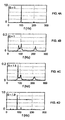
- FIG. 5A-F show experimental results for an arrangement according to FIG. 2.
- Frequency spectra of the signals from sensor 13 are compared for undamped (dashed lines) and, under various conditions, attenuated (solid lines) by compensatory feedback (solid lines) flow oscillations.
- conventional amplifier elements 28, 29, in the cases of FIG. 5D-F uses adaptive amplifier elements 28, 29 over the frequency range 0-500 Hz.
Landscapes
- Engineering & Computer Science (AREA)
- Physics & Mathematics (AREA)
- Fluid Mechanics (AREA)
- Mechanical Engineering (AREA)
- General Engineering & Computer Science (AREA)
- Measurement Of Mechanical Vibrations Or Ultrasonic Waves (AREA)
- Investigating Or Analyzing Materials By The Use Of Ultrasonic Waves (AREA)
Description
- universell, d. h. unabhängig von spezifischen Anregungsmechanismen für die Strömungsoszillationen funktioniert und
- möglichst effizient ist, d. h. möglichet wenig Loictung zum Dämpfen verbraucht,
- FIG. 1A
- eine Konfiguration für abgelöste instabile Strömung ohne globale Strömungsoszillation;
- FIG. 1B
- eine Konfiguration für abgelöste instabile Strömung mit schwach ausgeprägter globaler Strömungsoszillation;
- FIG. 1C
- eine Konfiguration für abgelöste instabile Strömung mit ausgeprägter antisymmetrischer globaler Strömungsoszillation;
- FIG. 1D
- eine Konfiguration für abgelöste instabile Strömung mit ausgeprägter symmetrischer globaler Strömungsoszillation;
- FIG. 1E-F
- Frequenzspektren der Signale eines Sensors zur Erfassung der Strömungsoszillationen der Konfigurationen in FIG. 1A-D;
- FIG. 2
- eine Anordnung zur aktiven Dämpfung von globalen Strömungsoszillationen mittels Rückkopplung: Querströmung als kompensatorische Oszillation;
- FIG. 3
- eine Anordnung zur Erzeugung einer kompensatorischen Oszillation: Oszillation eines Ablösepunktes;
- FIG. 4A-H
- Frequenzspektren von Sensorsignalen zur Erfassung von Strömungsoszillationen für verschiedene in der Ablösezone aufgeprägte kompensatorische Oszillationen;
- FIG. 5A-C
- Frequenzspektren von Sensorsignalen zur Erfassung von Strömungsoszillationen für schmalbandig phasenangepasste kompensatorische Rückkopplung;
- FIG. 5D-F
- Frequenzspektren von Sensorsignalen zur Erfassung von Strömungsoszillationen für breitbandig phasenangepasste kompensatorische Rückkopplung;
- FIG. 6A-B
- Sensorsignale zur Erfassung von Strömungsoszillationen als Funktion der Zeit beim An- und Abschalten der aktiven Dämpfung.
- FIG. 7
- Anordnung zur aktiven Dämpfung von Strömungsoszillationen an einem akustischen Resonator mit einer Öffnung, die einer Strömung längs einer Grenzfläche zugewandt ist.
- Erfassung der globalen Strömungsoszillationen mit einem Sensorsystem;
- Erzeugung einer kompensatorischen Oszillation in einer Ablösezone;
- Aufbereitung der Sensorsignale und Regelung der kompensatorischen Oszillation.
- die Rückwirkung der Strömung strömungsaufwärts, ausgelöst durch die Wechselwirkung der Strömung mit der Begrenzung 41 (Hindernis);
- die Wechselwirkung einer vom Ablösepunkt 11 ausgehenden instabilen Schicht mit einer akustischen Resonanz des Raumes 40.
Claims (17)
- Verfahren zum Dämpfen globaler Strömungsoszillationen (20a.x, 20b.x, 5a-b, 6a-b, 60) in einem strömenden Medium im Bereich von mindestens einer Ablösezone, die sich an einer eindeutig gegebenen Stelle einer Grenzfläche (11, 12) befindet und an der sich eine instabile Strömung (10) ablöst,
in welchem Verfahren die globalen Strömungsoszillationen mit einem Sensorsystem (13, 42, 50) erfasst werden, das stromabwärts nach der Ablösezone angeordnet ist, und
dem strömenden Medium eine mit den Signalen des Sensorsystems geregelte (28, 29, 44) kompensatorische Oszillation (15, 16, 34, 35) in der Ablösezone der Strömung aufgeprägt wird. - Verfahren nach Anspruch 1, dadurch gekennzeichnet, dass die globale Strömungsoszillation durch Messung des Druckes oder der Strömungsgeschwindigkeit an einem vorgegeben Punkt im strömenden Medium erfasst wird.
- Verfahren nach Anspruch 1, dadurch gekennzeichnet, dass die globale Strömungsoszillation durch Beeinflussung der abgelösten instabilen Strömung durch ein Hindernis (7, 8, 14, 41) hervorgerufen und durch Messung der Kraft, die die Strömung auf das Hindernis ausübt, erfasst wird.
- Verfahren nach einem der Ansprüche 1-3, dadurch gekennzeichnet, dass als kompensatorische Strömungsoszillation ein Strömungsfeld (17, 18, 46) in mindestens einer Ablösezone generiert wird und/oder eine Oszillation (34, 35) mindestens eines Ablösepunktes (11, 12) der abgelösten Strömung angeregt wird.
- Verfahren nach einem der Ansprüche 1-4, dadurch gekennzeichnet, dass die globale Strömungsoszillation dadurch erfasst wird, dass die Signale des Sensorsystems (13, 42, 50) ausgewertet werden und mit Hilfe dieser Auswertung globale Strömungsoszillationen hinsichtlich ihrer Frequenz und/oder Intensität und/oder Phase charakterisiert werden.
- Verfahren nach einem der Ansprüche 1-5, dadurch gekennzeichnet, dass die Signale des Sensorsystems durch Verstärkung (28, 29, 44) und/oder Frequenzfilterung (25) und/oder Phasenverschiebung (28, 29, 44) modifiziert werden und die so modifizierten Signale zur Erzeugung der kompensatorischen Oszillation verwendet werden.
- Verfahren nach Anspruch 6, dadurch gekennzeichnet, dass die Verstärkung und die Phasenverschiebung mit adaptiven Verstärkerelementen über einen vorgegebenen Frequenzbereich nach vorgegebenen Regeln so angepasst werden, dass die Intensität der Strömungsoszillation einen vorgegebenen Wert unterschreitet.
- Verfahren nach einem der Ansprüche 1-7, dadurch gekennzeichnet, dass die abgelöste instabile Strömung und/oder die globalen Strömungsoszillationen mit einer akustischen Welle wechselwirken.
- Verfahren nach Anspruch 8, dadurch gekennzeichnet, dass die akustische Welle von einem akustischen Resonator (40) beeinflusst wird.
- Verfahren nach einem der Ansprüche 8-9, dadurch gekennzeichnet, dass das Sensorsystem die globale Strömungsoszillation mittels eines Sensors (42) erfasst, der die akustische Welle charakterisiert.
- Vorrichtung zur Anwendung des Verfahrens nach einem der Ansprüche 1-10 auf globale Strömungsoszillationen (20a.x, 20b.x, 5a-b, 6a-b, 60) in einem strömenden Medium im Bereich von mindestens einer Ablösezone, die sich an einer eindeutig gegebenen Stelle einer Grenzfläche (11, 12) befindet und an der sich eine instabile Strömung (10) ablöst,
welche Vorrichtung ein Sensorsystem (13, 42, 50), ein Generator (17, 18, 46) und ein Regelsystem (28, 29, 44) enthält,
wobei das Sensorsystem, mit dem die globalen Strömungsoszillationen erfassbar sind, stromabwärts nach der Ablösezone angeordnet ist,
der Generator dem strömenden Medium eine kompensatorische Oszillation (15, 16, 34, 35) in der Ablösezone der Strömung aufprägt und
das Regelsystem die Signale des Sensorsystems auswertet sowie die kompensatorische Oszillation so regelt, dass die Amplitude der globalen Strömungsoszillation um einen vorgegebenen Faktor gedämpft wird. - Vorrichtung nach Anspruch 11 mit einem Hindernis (7, 8, 14, 41) in der abgelösten instabilen Strömung, welches die globalen Strömungsoszillationen verursacht.
- Vorrichtung nach Anspruch 12, dadurch gekennzeichnet, dass das Sensorsystem einen Sensor zur Messung der von der Strömung auf das Hindernis ausgeübten Kraft enthält.
- Vorrichtung nach einem der Ansprüche 11-13, dadurch gekennzeichnet, dassdie kompensatorische Oszillation ein Strömungsfeld (15,16) ist und der Generator mindestens eine Erregungsquelle (17, 18) für die Erzeugung des Strömungsfeld, enthält, oder dassdie kompensatorische Oszillation eine Oszillation mindestens eines Ablösepunktes (11, 12) ist und zur Erregung der Oszillation der Ablösepunkte bewegliche Begrenzungselemente (34, 35) für die abgelöste Strömung, welche Begrenzungselemente die Position der Ablösepunkte (11, 12) definieren, vorgesehen sind, wobei der Generator eine Vorrichtung für die Erzeugung einer Bewegung der Begrenzungselemente enthält, welche Bewegung die Oszillation der Ablösepunkte bewirkt.
- Vorrichtung nach einem der Ansprüche 11-14, dadurch gekennzeichnet, dass das Regelsystem ein Frequenzfilter (25) und/oder einen Frequenzanalysator und/oder einen Verstärker (28, 29, 44) und/oder einen Phasenschieber (28, 29, 44) für die Verarbeitung der Signale des Sensorsystems enthält.
- Vorrichtung nach einem der Ansprüche 11-15, dadurch gekennzeichnet, dass die abgelöste instabile Strömung an einer dem strömenden Medium abgewandten Einbuchtung (40) in einer Grenzfläche entsteht.
- Flug- oder Schwimmkörper oder Fahrzeuge mit einer Vorrichtung nach einem der Ansprüche 11-16 zur Dämpfung einer globalen Strömungsoszillation an der Oberfläche.
Priority Applications (4)
| Application Number | Priority Date | Filing Date | Title |
|---|---|---|---|
| DE59510549T DE59510549D1 (de) | 1995-03-14 | 1995-03-14 | Verfahren zum aktiven Dämpfen globaler Strömungsoszillationen in abgelösten instabilen Strömungen und Vorrichtung zur Anwendung des Verfahrens |
| EP95810167A EP0732513B1 (de) | 1995-03-14 | 1995-03-14 | Verfahren zum aktiven Dämpfen globaler Strömungsoszillationen in abgelösten instabilen Strömungen und Vorrichtung zur Anwendung des Verfahrens |
| JP8014417A JPH08261212A (ja) | 1995-03-14 | 1996-01-30 | 分離された不安定なフロー内においてグローバル・フロー・オシレーションを能動的に減衰する方法及びその方法を実施するための装置 |
| US08/608,397 US5798465A (en) | 1995-03-14 | 1996-02-28 | Method for actively damping global flow oscillations in separated unstable flows and an apparatus for performing the method |
Applications Claiming Priority (1)
| Application Number | Priority Date | Filing Date | Title |
|---|---|---|---|
| EP95810167A EP0732513B1 (de) | 1995-03-14 | 1995-03-14 | Verfahren zum aktiven Dämpfen globaler Strömungsoszillationen in abgelösten instabilen Strömungen und Vorrichtung zur Anwendung des Verfahrens |
Publications (2)
| Publication Number | Publication Date |
|---|---|
| EP0732513A1 EP0732513A1 (de) | 1996-09-18 |
| EP0732513B1 true EP0732513B1 (de) | 2003-02-05 |
Family
ID=8221710
Family Applications (1)
| Application Number | Title | Priority Date | Filing Date |
|---|---|---|---|
| EP95810167A Expired - Lifetime EP0732513B1 (de) | 1995-03-14 | 1995-03-14 | Verfahren zum aktiven Dämpfen globaler Strömungsoszillationen in abgelösten instabilen Strömungen und Vorrichtung zur Anwendung des Verfahrens |
Country Status (4)
| Country | Link |
|---|---|
| US (1) | US5798465A (de) |
| EP (1) | EP0732513B1 (de) |
| JP (1) | JPH08261212A (de) |
| DE (1) | DE59510549D1 (de) |
Families Citing this family (18)
| Publication number | Priority date | Publication date | Assignee | Title |
|---|---|---|---|---|
| US5983944A (en) * | 1998-03-20 | 1999-11-16 | Niv; Shaul E. | Apparatus for active fluid control |
| US6405794B1 (en) * | 1999-03-07 | 2002-06-18 | Korea Institute Of Science And Technology | Acoustic convection apparatus |
| JP4677744B2 (ja) * | 2003-11-04 | 2011-04-27 | ソニー株式会社 | 噴流発生装置、電子機器及び噴流発生方法 |
| JP4572548B2 (ja) * | 2004-03-18 | 2010-11-04 | ソニー株式会社 | 気体噴出装置 |
| JP4747657B2 (ja) * | 2005-04-21 | 2011-08-17 | ソニー株式会社 | 噴流発生装置及び電子機器 |
| JP2006310586A (ja) * | 2005-04-28 | 2006-11-09 | Sony Corp | 気流発生装置及び電子機器 |
| US20070023169A1 (en) * | 2005-07-29 | 2007-02-01 | Innovative Fluidics, Inc. | Synthetic jet ejector for augmentation of pumped liquid loop cooling and enhancement of pool and flow boiling |
| US7932535B2 (en) * | 2005-11-02 | 2011-04-26 | Nuventix, Inc. | Synthetic jet cooling system for LED module |
| US7607470B2 (en) * | 2005-11-14 | 2009-10-27 | Nuventix, Inc. | Synthetic jet heat pipe thermal management system |
| US8030886B2 (en) | 2005-12-21 | 2011-10-04 | Nuventix, Inc. | Thermal management of batteries using synthetic jets |
| US8035966B2 (en) * | 2006-02-23 | 2011-10-11 | Nuventix, Inc. | Electronics package for synthetic jet ejectors |
| JP5037046B2 (ja) * | 2006-07-03 | 2012-09-26 | 学校法人同志社 | 流体噴出装置 |
| DE102007024372B4 (de) * | 2007-05-23 | 2016-02-18 | Airbus Defence and Space GmbH | Einrichtung zur Lärmreduzierung an einem Hochauftriebssystem am Tragflügel eines Flugzeugs |
| DE102007024371B4 (de) * | 2007-05-23 | 2020-03-05 | Airbus Defence and Space GmbH | Verfahren und Einrichtung zur Strömungskontrolle an einem Hochauftriebssystem am Tragflügel eines Flugzeugs |
| US10274263B2 (en) | 2009-04-09 | 2019-04-30 | General Electric Company | Method and apparatus for improved cooling of a heat sink using a synthetic jet |
| US9615482B2 (en) | 2009-12-11 | 2017-04-04 | General Electric Company | Shaped heat sinks to optimize flow |
| US8776871B2 (en) | 2009-11-19 | 2014-07-15 | General Electric Company | Chassis with distributed jet cooling |
| RU2706864C1 (ru) * | 2019-03-25 | 2019-11-21 | Федеральное государственное унитарное предприятие "Всероссийский научно-исследовательский институт расходометрии" (ФГУП "ВНИИР") | Устройство для бескавитационного истечения воды |
Family Cites Families (14)
| Publication number | Priority date | Publication date | Assignee | Title |
|---|---|---|---|---|
| US3334641A (en) * | 1964-06-26 | 1967-08-08 | Johnson Service Co | Fluid stream control apparatus |
| US3362663A (en) * | 1966-03-23 | 1968-01-09 | Boeing Co | Reduction of turbulence and drag by mechanical vibrations |
| US3774867A (en) * | 1972-06-27 | 1973-11-27 | Us Air Force | Acoustic wing stall delaying device |
| IL52613A (en) * | 1977-07-28 | 1980-11-30 | Univ Ramot | Method and apparatus for controlling the mixing of two fluids |
| DE3228939C1 (de) * | 1982-08-03 | 1983-11-24 | Messerschmitt-Bölkow-Blohm GmbH, 8000 München | Verfahren und Einrichtung zur Beeinflussung der Grenzschicht von umstroemten Koerpern |
| FR2531676A1 (fr) * | 1982-08-11 | 1984-02-17 | Onera (Off Nat Aerospatiale) | Procede et installation de reduction du tremblement de la voilure d'un aeronef au moyen de gouvernes actives |
| US4813631A (en) * | 1982-09-13 | 1989-03-21 | The Boeing Company | Laminar flow control airfoil |
| GB2139734B (en) * | 1983-05-05 | 1987-05-28 | Messerschmitt Boelkow Blohm | Method of and apparatus for influencing the boundary layer of a body experiencing predominantly stochastic flow fluctuations |
| DE3342421C2 (de) * | 1983-11-24 | 1987-01-29 | Messerschmitt-Bölkow-Blohm GmbH, 8012 Ottobrunn | Verfahren zur stabilisierenden Beeinflussung abgelöster laminarer Grenzschichten |
| US4932610A (en) * | 1986-03-11 | 1990-06-12 | The United States Of America As Represented By The United States National Aeronautics And Space Administration | Active control of boundary layer transition and turbulence |
| US4802642A (en) * | 1986-10-14 | 1989-02-07 | The Boeing Company | Control of laminar flow in fluids by means of acoustic energy |
| DE3738366A1 (de) * | 1987-11-12 | 1989-05-24 | Deutsche Forsch Luft Raumfahrt | Verfahren und vorrichtung zur erzeugung eines laminar-turbulenten grenzschichtuebergangs bei umstroemten koerpern |
| US5209438A (en) * | 1988-06-20 | 1993-05-11 | Israel Wygnanski | Method and apparatus for delaying the separation of flow from a solid surface |
| US5040560A (en) * | 1990-12-05 | 1991-08-20 | Ari Glezer | Method and apparatus for controlled modification of fluid flow |
-
1995
- 1995-03-14 DE DE59510549T patent/DE59510549D1/de not_active Expired - Fee Related
- 1995-03-14 EP EP95810167A patent/EP0732513B1/de not_active Expired - Lifetime
-
1996
- 1996-01-30 JP JP8014417A patent/JPH08261212A/ja active Pending
- 1996-02-28 US US08/608,397 patent/US5798465A/en not_active Expired - Fee Related
Also Published As
| Publication number | Publication date |
|---|---|
| DE59510549D1 (de) | 2003-03-13 |
| US5798465A (en) | 1998-08-25 |
| EP0732513A1 (de) | 1996-09-18 |
| JPH08261212A (ja) | 1996-10-08 |
Similar Documents
| Publication | Publication Date | Title |
|---|---|---|
| EP0732513B1 (de) | Verfahren zum aktiven Dämpfen globaler Strömungsoszillationen in abgelösten instabilen Strömungen und Vorrichtung zur Anwendung des Verfahrens | |
| DE3883599T2 (de) | System zur Modenunterdrückung für Flugzeuge. | |
| DE69319004T2 (de) | Verfahren und Gerät zur Steuerung eines Magnetlagers | |
| DE69305843T2 (de) | Aktives lärmverminderungssystem eines hubschraubers | |
| DE4340034C1 (de) | Lagerung | |
| DE102008025298A1 (de) | Verfahren und Vorrichtung zur aktiven Dämpfung von Vertikalschwingungen bei einem Hubschrauber mit angehängter Außenlast | |
| EP0985810A1 (de) | Verfahren und Vorrichtung zum Minimieren thermoakustischer Schwingungen in Gasturbinenbrennkammern | |
| EP1050713A1 (de) | Verfahren zur Unterdrückung bzw. Kontrolle von thermoakustischen Schwingungen in einem Verbrennungssystem sowie Verbrennungssystem zur Durchführung des Verfahrens | |
| EP1876428A1 (de) | Verfahren zum Betreiben eines Coriolis-Massendurchflussmessgerätes | |
| DE69119562T2 (de) | Steuerungssystem mit gleitender Wirkungsweise | |
| DE102018105543A1 (de) | Schwingungsstruktur-Drehraten-Sensor | |
| EP3329335B1 (de) | Dämpfung von lastschwingungen ohne zusätzliche messmittel an der lastseite | |
| DE10043128C2 (de) | Tilgervorrichtung zur Absorption einer unerwünschten Erregung | |
| EP0918152A1 (de) | Verfahren und Vorrichtung zur Kontrolle thermoakustischer Schwingungen in einem Verbrennungssystem | |
| EP0931312B1 (de) | Verfahren zum regeln der fokussierung und der führung eines lichtstrahls | |
| DE10046898B4 (de) | Verfahren zum Regeln des Arbeitspunktes eines Modulators und zugehörige Ansteuereinheit | |
| EP1439437B1 (de) | Verfahren zur aktiven Dämpfung niederfrequenter Schwingungen an numerisch gesteuerten Werkzeugmaschinen | |
| DE10257244A1 (de) | Verfahren und Vorrichtung zur Beeinflussung thermoakustischer Schwingungen in Verbrennungssystemen | |
| DE10137496B4 (de) | Verfahren und Reglungsstruktur zur Dämpfung von niederfrequenten Lastschwingungen bei Antrieben mit Motor und Last | |
| DE102008044664B4 (de) | Verfahren zur Frequenzregelung einer Oszillatoranordnung | |
| DE19501136C2 (de) | Verfahren und Einrichtung zur Dämpfung von Fahrschwingungen bei Fahrzeugen | |
| DE4133407C2 (de) | Anordnung zur Kompensation des durch eine schwingende Wand abgestrahlten Schalles | |
| EP1607325B1 (de) | Vorrichtung und Verfahren zur Bedämpfung mindestens einer Starrkörpereigenform und/oder mindestens einer elastischen Eigenbewegungsform eines Luftfahrzeuges | |
| EP1429002A2 (de) | Verfahren und Vorrichtung zur Beeinflussung thermoakustischer Schwingungen in Verbrennungssystemen | |
| DE102009038775B4 (de) | Regeleinrichtung und Verfahren zur Regelung eines Magnetlagers |
Legal Events
| Date | Code | Title | Description |
|---|---|---|---|
| PUAI | Public reference made under article 153(3) epc to a published international application that has entered the european phase |
Free format text: ORIGINAL CODE: 0009012 |
|
| AK | Designated contracting states |
Kind code of ref document: A1 Designated state(s): CH DE FR GB LI |
|
| AX | Request for extension of the european patent |
Free format text: SI |
|
| RAX | Requested extension states of the european patent have changed |
Free format text: SI |
|
| 17P | Request for examination filed |
Effective date: 19970210 |
|
| 17Q | First examination report despatched |
Effective date: 20000802 |
|
| RAP1 | Party data changed (applicant data changed or rights of an application transferred) |
Owner name: SULZER MARKETS AND TECHNOLOGY AG |
|
| GRAG | Despatch of communication of intention to grant |
Free format text: ORIGINAL CODE: EPIDOS AGRA |
|
| GRAG | Despatch of communication of intention to grant |
Free format text: ORIGINAL CODE: EPIDOS AGRA |
|
| GRAH | Despatch of communication of intention to grant a patent |
Free format text: ORIGINAL CODE: EPIDOS IGRA |
|
| GRAH | Despatch of communication of intention to grant a patent |
Free format text: ORIGINAL CODE: EPIDOS IGRA |
|
| GRAA | (expected) grant |
Free format text: ORIGINAL CODE: 0009210 |
|
| AK | Designated contracting states |
Designated state(s): CH DE FR GB LI |
|
| REG | Reference to a national code |
Ref country code: GB Ref legal event code: FG4D Free format text: NOT ENGLISH |
|
| REG | Reference to a national code |
Ref country code: CH Ref legal event code: EP |
|
| GBT | Gb: translation of ep patent filed (gb section 77(6)(a)/1977) |
Effective date: 20030205 |
|
| REF | Corresponds to: |
Ref document number: 59510549 Country of ref document: DE Date of ref document: 20030313 Kind code of ref document: P |
|
| PGFP | Annual fee paid to national office [announced via postgrant information from national office to epo] |
Ref country code: GB Payment date: 20030314 Year of fee payment: 9 |
|
| REG | Reference to a national code |
Ref country code: CH Ref legal event code: NV Representative=s name: SULZER MANAGEMENT AG |
|
| PGFP | Annual fee paid to national office [announced via postgrant information from national office to epo] |
Ref country code: CH Payment date: 20030318 Year of fee payment: 9 |
|
| PGFP | Annual fee paid to national office [announced via postgrant information from national office to epo] |
Ref country code: FR Payment date: 20030319 Year of fee payment: 9 Ref country code: DE Payment date: 20030319 Year of fee payment: 9 |
|
| ET | Fr: translation filed | ||
| PLBE | No opposition filed within time limit |
Free format text: ORIGINAL CODE: 0009261 |
|
| STAA | Information on the status of an ep patent application or granted ep patent |
Free format text: STATUS: NO OPPOSITION FILED WITHIN TIME LIMIT |
|
| 26N | No opposition filed |
Effective date: 20031106 |
|
| PG25 | Lapsed in a contracting state [announced via postgrant information from national office to epo] |
Ref country code: GB Free format text: LAPSE BECAUSE OF NON-PAYMENT OF DUE FEES Effective date: 20040314 |
|
| PG25 | Lapsed in a contracting state [announced via postgrant information from national office to epo] |
Ref country code: LI Free format text: LAPSE BECAUSE OF NON-PAYMENT OF DUE FEES Effective date: 20040331 Ref country code: CH Free format text: LAPSE BECAUSE OF NON-PAYMENT OF DUE FEES Effective date: 20040331 |
|
| PG25 | Lapsed in a contracting state [announced via postgrant information from national office to epo] |
Ref country code: DE Free format text: LAPSE BECAUSE OF NON-PAYMENT OF DUE FEES Effective date: 20041001 |
|
| GBPC | Gb: european patent ceased through non-payment of renewal fee |
Effective date: 20040314 |
|
| REG | Reference to a national code |
Ref country code: CH Ref legal event code: PL |
|
| PG25 | Lapsed in a contracting state [announced via postgrant information from national office to epo] |
Ref country code: FR Free format text: LAPSE BECAUSE OF NON-PAYMENT OF DUE FEES Effective date: 20041130 |
|
| REG | Reference to a national code |
Ref country code: FR Ref legal event code: ST |