EP0732600A2 - Magnétomètre active à impulsion - Google Patents
Magnétomètre active à impulsion Download PDFInfo
- Publication number
- EP0732600A2 EP0732600A2 EP96301239A EP96301239A EP0732600A2 EP 0732600 A2 EP0732600 A2 EP 0732600A2 EP 96301239 A EP96301239 A EP 96301239A EP 96301239 A EP96301239 A EP 96301239A EP 0732600 A2 EP0732600 A2 EP 0732600A2
- Authority
- EP
- European Patent Office
- Prior art keywords
- magnetic
- further characterized
- vessel
- magnetometer system
- magnetometer
- Prior art date
- Legal status (The legal status is an assumption and is not a legal conclusion. Google has not performed a legal analysis and makes no representation as to the accuracy of the status listed.)
- Granted
Links
Images


Classifications
-
- G—PHYSICS
- G01—MEASURING; TESTING
- G01V—GEOPHYSICS; GRAVITATIONAL MEASUREMENTS; DETECTING MASSES OR OBJECTS; TAGS
- G01V3/00—Electric or magnetic prospecting or detecting; Measuring magnetic field characteristics of the earth, e.g. declination, deviation
- G01V3/08—Electric or magnetic prospecting or detecting; Measuring magnetic field characteristics of the earth, e.g. declination, deviation operating with magnetic or electric fields produced or modified by objects or geological structures or by detecting devices
Definitions
- the present invention relates to systems for detecting metal objects such as mines in shallow salt water, and more particularly to a detection system employing a magnetic impulse waveform generated by a magnetic field transmitter which is received by a separate receiver element.
- a fixed frequency oscillator is used as the transmitter.
- the transmitter develops an "electro-magnetic field" in some form of a coil.
- a similar coil arrangement is used at the receiver.
- the receiver is designed so that the direct path energy is canceled in the receiver.
- the receiver output is sensitive only to disturbances in the "electro magnetic field” near the coil. (Frequently these changes are just capacitance or inductance change effects on a tuned circuit.)
- Metal targets are detected as an "unbalanced" condition in the receiver.
- the coils are moved around over the suspected target area.
- the metal object is located at the point where the maximum receiver output is achieved, directly over the mine or other metal object.
- Sonar systems have also been tried for mine detection in shallow salt water. However, sonar has a very difficult time operating in shallow water and near the surf. Sonar also has a difficult time with mine size targets on the bottom or which are buried.
- Impulse radars Ultra Wide Band
- 1 to 10 nanosecond impulse radars work quite well in dry soil and even in fresh water or snow.
- salt water the attenuation of greater than 60 db per foot is a prohibitive signal loss factor.
- Magnetometers have been very successful in the detection of slight variations in the earth's static magnetic field. These devices are used for submarine detection at depths of more than 500 feet.
- the Navy has long used VLF communications systems which have negligible salt water signal attenuations at 10 KHz to 40 KHz carrier frequencies for communications with submarines below the sea and around the world.
- An active impulse magnetometer for detecting metal objects such as mines in shallow water.
- the magnetometer comprises a magnetic transmitter element secured on a movable vehicle, and a pulse generator for driving said transmitter element to transmit first and second magnetic pulses of opposite polarity.
- a magnetic receiver element is secured on the vehicle in a spaced relationship relative to the transmitter element.
- the magnetometer further includes means for measuring an impulse response to the magnetic pulses, comprising means responsive to magnetic signals received at the receiver element in response to the transmitted magnetic pulses for performing a fast Fourier transformation of the received signals.
- the magnetometer includes means for providing a vehicle location signal indicative of a present location of the vehicle, and signal processor responsive to the transformed received signals and to the vehicle location signal to locate metal targets causing disturbances in the magnetic impulse response.
- the movable vehicle is a water vessel
- the magnetic transmitter element is mounted along one of the port or starboard sides of the vessel
- the magnetic receiver element is mounted along the other of the port or starboard sides.
- a controller for controlling for controlling the operation of the pulse generator and measuring means.
- the controller comprising means for blanking operation of the measuring means during the first magnetic pulse transmission, and for enabling operation of the measuring means during transmission of the second pulse.
- This invention is an active impulse magnetometer (AIM). It uses a magnetic impulse wave form generated by a magnetic field transmitter which is received by a separate bi-static "active magnetometer” receiver element. This unique waveform has been found to penetrate through aluminum, steel and other metals with little or no attenuation. Tests have demonstrated that a low frequency magnetic impulse has very little loss through ocean salt water. Tests further show that metal targets which are in the sensor field anywhere around the magnetic field generator can be detected as the cause of variations in the received field.
- AIM active impulse magnetometer
- the AIM system is well suited for the detection of metal mines in ocean water. Other applications such as enhanced submarine detection and underwater communications are contemplated.
- FIGS. 1 and 2 show an embodiment of the sensor 50 mounted on a vessel 20 such as a ship or boat.
- the sensor system 50 includes a transmitter transducer element 52 and a receiver transducer element 54 mounted on opposite sides of the vessel 20.
- the objective of the sensor system 50 is to detect the presence and location of a submerged metal target 80.
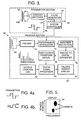
- FIG. 3 illustrates a schematic block diagram of the sensor system 50.
- a system controller 60 controls the operation of the system.
- a transmit section 56 comprises a pulse generator 62, a current switcher 64 and the transmit propagator element 52.
- the controller 60 triggers the pulse generator to generate a two pulse waveform, as shown in FIG. 8.
- the current switcher 64 operates to invert the polarity of the second pulse, to create the transmit waveform shown in FIG. 4A.
- the transmit waveform is applied to the transmit propagation element 52, which comprises coil 52A wound about a core 52B.
- This unique bipolar magnetic impulse waveform is preferred over more conventional mono-polar waveforms because the rate of change of the magnetic field from a positive field to a negative field provides improved receiver sensitivity, better time reference as well as better control of the transmitted magnetic field waveform.
- the receiver section 58 of the sensor 50 includes the receiver element 54, a preamplifier 70 for applying a first amplification level to the signals received by the receiver transducer element 54.
- the output from the preamplifier is passed through a programmable attenuator 72, whose attenuation level is set by the controller 60 to operate the receiver in an effective desired on/off state.
- the receiver 58 When the attenuator 72 is controlled to provide maximum attenuation to the received, pre-amplified signal, the receiver 58 is effectively "off”; with a minimum attenuation level set in the attenuator, the receiver is effectively "on.”
- the controller 60 provides a blanking signal to the attenuator 72 to put the receiver in an "off” state during transmission of a positive magnetic pulse, and removes the blanking signal to put the receiver in an on state during transmission of the negative magnetic pulse.
- the output of the attenuator 72 is passed to an amplifier/filter section 74, where the received signal is amplified further and filtered. This filtering is preferred to reduce 50 Hz or 60 Hz and harmonics thereof, and/or other primary power line frequencies which are often found in harbors and near shore.
- An analog-to-digital convertor (ADC) 76 converts the amplified, filtered signal into a digital value. In the preferred system there are 1024 digital samples over a 100 millisecond period of time. The digitized signal is applied to the Fast Fourier Transform device 78, which produces a frequency spectrum with 10 Hz resolution over a frequency range of 10 Hz to 10.24 kHz.
- the transformed signal is processed by the digital signal processor (DSP) 80, which also knows the vessel location as a result of a vehicle location log 82.
- the DSP 80 controls a falling raster display 84 to display the frequency domain signals versus the vehicle location, as shown in FIG. 5.
- the transmitter section 56 of the sensor system 50 provides an impulse magnetic field waveform.
- a carrier signal is usually employed, upon which "modulation" is placed which contains the information to be transmitted. It is equally reasonable to transmit the information by a "coded sequence" of impulses which are one cycle of the center frequency of the radio band selected for the data transmission. Multiple single impulses would form a data stream which could be transmitted directly, without a carrier, from one location to another. This form of communication is referred to as impulse data transmission.
- FIG. 6 illustrates a schematic diagram of an exemplary embodiment of the current switcher 64 comprising the transmitter.
- the current switcher 64 includes two pairs of switches S11, S12, S21 and S22, each of which is controlled by a switch control gate comprising the pulse generator 62.
- Two resistors 64A and 64B are connected in parallel to a voltage source at +V.
- Switches S11 and S12 are connected in series from node 64C to ground.
- Switches S21 and S22 are connected in series from node 64D to ground.
- Capacitors 64E and 64F are connected from respective nodes 64C and 64D to ground, in parallel with the respective switch pairs.
- Node 64G and 64H are connected to the transmission line 64I. The other end of the transmission line 64I is connected to the transmitter coil 64J.
- the switch pairs provide a means of applying a voltage of selectable polarity to the transmitter coil 64J.
- Each capacitor 64E and 64F will be charged to a voltage V.
- Closing switches S11 and S22 while leaving open switches S12 and S21 will apply a voltage pulse of a first polarity to the transmitter coil 64J.
- Closing switches S21 and S12 while leaving open switches S11 and S22 will apply a voltage pulse of a second polarity to the transmitter coil 64J.
- FIG. 7 is a schematic diagram of an exemplary pulse generator 62.
- the switches S11, S12, S21 and S22 of the current switcher 64 are controlled by a pair of switch control gates 62A and 62B comprising the pulse generator 62.
- a trigger generator 62C is clocked by a clock signal, and receives a code signal from the system controller 60. This code signal operates the trigger generator 62C to initiate trigger pulses +P and -P.
- the pulse waveform is shown in FIG. 8.
- the pulse +P is active, to close switches S11 and S22, and the pulse -P is not active, leaving open switches S12 and S21.
- the pulse -P is active, to close switches S21 and S12, and the pulse +P is not active, leaving open switches S11 and S22.
- the output power of the impulse switch is primarily dependent upon the maximum voltage allowed for switching and on the impedance of the devices S11, S12, S21 and S22 being switched. The faster the switch is toggled from ON to OFF the smaller the amount of heat that must be dissipated from the device during switching. Fast switching times faster than 100 microseconds are preferred to create a good harmonic content in the waveform.
- the amplitude and phase of each of the harmonic spectral lines will be determined by the net sum of all of the energy received at the receiving element 54, from all fixed metal objects near the system.
- the net sum of the received energy will change based upon changes in the fields caused by other metal objects when encountered.
- the sensor will indicate changes at any location around the craft.
- a computerized histogram of the relative amplitude and phase disturbances (or differences) will localize the location of the metal device at right angles to the path of travel. This is in effect a "spherical ring" around the platform of maximum sensitivity.
- audio output signals could be provided to a swimmer using earphones or some other form of audio transducer. Indicator lights could also be used when desired.
- the AIM system can be maneuvered along the beach 300 to 500 feet from the beach on the first pass.
- the data from this pass is recorded in a computer and displayed as an "intensity varying strip chart" on the display screen.
- the boat would then move in closer by 100 feet or so and make another pass. This would continue until the boat was as close as safely possible.
- the mines and any other metal objects would show up as changes in intensity on the display screen at the point in the path where the sensor was the closest to the mines. This same process can be done covertly using a submerged mini-sub or remotely controlled vehicle.
- the magnetic propagators are mounted on each side of a small boat below the water line.
- each element is approximately 1.5 to 2 inches in diameter.
- Each element is housed in a PVC plastic tube (or equivalent) which is sealed.
- the transmitter propagator elements and the receiver elements are 6 to 8 feet long for target ranges of 20 to 40 feet. It is preferred to have a spacing of 6 to 8 feet between the propagator and receiver elements.
- the mines in the shallow water areas are typically in metal containers with pressure sensors, magnetic sensors or trip wire activators. They may be on the bottom or buried in the sand. The typical water depths of up to 40 feet are expected.
- a sensor which detects these mines should be capable of working while submerged with distances between the surface and the bottom of 5 feet to as much as 50 feet. Preferably, there is a method of "marking" the mine location once they have been detected to that they can be avoided or destroyed. It would also be highly desirable to identify mines located in the surf and on the beach.
- GPS global positioning system
- An active impulse magnetometer in accordance with the invention provides efficient detection of metal mines in shallow sea water. Some of the characteristics of the system are:
Landscapes
- Life Sciences & Earth Sciences (AREA)
- Engineering & Computer Science (AREA)
- Physics & Mathematics (AREA)
- Remote Sensing (AREA)
- Geology (AREA)
- Environmental & Geological Engineering (AREA)
- Electromagnetism (AREA)
- General Life Sciences & Earth Sciences (AREA)
- General Physics & Mathematics (AREA)
- Geophysics (AREA)
- Geophysics And Detection Of Objects (AREA)
- Near-Field Transmission Systems (AREA)
- Measuring Magnetic Variables (AREA)
- Investigating Or Analyzing Materials By The Use Of Magnetic Means (AREA)
Applications Claiming Priority (2)
| Application Number | Priority Date | Filing Date | Title |
|---|---|---|---|
| US08/405,690 US5525907A (en) | 1995-03-17 | 1995-03-17 | Active impulse magnetometer with bipolar magnetic impulse generator and fast fourier transform receiver to detect sub-surface metallic materials |
| US405690 | 1995-03-17 |
Publications (3)
| Publication Number | Publication Date |
|---|---|
| EP0732600A2 true EP0732600A2 (fr) | 1996-09-18 |
| EP0732600A3 EP0732600A3 (fr) | 1998-08-05 |
| EP0732600B1 EP0732600B1 (fr) | 2002-11-13 |
Family
ID=23604801
Family Applications (1)
| Application Number | Title | Priority Date | Filing Date |
|---|---|---|---|
| EP96301239A Expired - Lifetime EP0732600B1 (fr) | 1995-03-17 | 1996-02-23 | Magnétomètre à impulsion active |
Country Status (4)
| Country | Link |
|---|---|
| US (1) | US5525907A (fr) |
| EP (1) | EP0732600B1 (fr) |
| JP (1) | JP2869033B2 (fr) |
| DE (1) | DE69624739T2 (fr) |
Families Citing this family (42)
| Publication number | Priority date | Publication date | Assignee | Title |
|---|---|---|---|---|
| US5721489A (en) * | 1995-10-06 | 1998-02-24 | Garrett Electronics, Inc. | Metal detector method for identifying target size |
| US6084412A (en) * | 1997-03-24 | 2000-07-04 | The Johns Hopkins University | Imaging objects in a dissipative medium by nearfield electromagnetic holography |
| US5952833A (en) | 1997-03-07 | 1999-09-14 | Micron Technology, Inc. | Programmable voltage divider and method for testing the impedance of a programmable element |
| US6700939B1 (en) * | 1997-12-12 | 2004-03-02 | Xtremespectrum, Inc. | Ultra wide bandwidth spread-spectrum communications system |
| US6064209A (en) * | 1998-05-18 | 2000-05-16 | Xtech Explosive Decontamination, Inc. | Apparatus and process for clearance of unexploded ordinance |
| US6104193A (en) * | 1998-09-15 | 2000-08-15 | Aetc Inc. | System and method for detecting low metal content buried mines |
| US7346120B2 (en) * | 1998-12-11 | 2008-03-18 | Freescale Semiconductor Inc. | Method and system for performing distance measuring and direction finding using ultrawide bandwidth transmissions |
| US6218831B1 (en) * | 1999-05-19 | 2001-04-17 | Arthur D. Little, Inc. | Low power fluxgate circuit with current balance |
| US7388370B2 (en) * | 2005-07-29 | 2008-06-17 | Automotive Systems Laboratory Systems, Inc. | Magnetic crash sensor |
| US20070188168A1 (en) * | 1999-08-26 | 2007-08-16 | Stanley James G | Magnetic sensor |
| US7190161B2 (en) * | 1999-08-26 | 2007-03-13 | Automotive Systems Laboratory, Inc. | Magnetic sensor |
| US7514917B2 (en) * | 2003-09-19 | 2009-04-07 | Automotive Systems Laboratory, Inc. | Magnetic crash sensor |
| AUPR083700A0 (en) * | 2000-10-17 | 2000-11-09 | Bhc Consulting Pty Ltd | Ground mineralisation rejecting metal detector (transmit signal) |
| AU783784B2 (en) * | 2000-10-17 | 2005-12-08 | Minelab Electronics Pty Limited | Ground mineralisation rejecting metal detector (transmit signal) |
| AUPR083800A0 (en) * | 2000-10-17 | 2000-11-09 | Bhc Consulting Pty Ltd | Ground mineralisation rejecting metal detector (power saving) |
| US6414492B1 (en) * | 2000-11-02 | 2002-07-02 | Amalgamated Explorations, Inc. | Method and apparatus for passive detection of geophysical discontinuities in the earth |
| EP1428033A4 (fr) * | 2001-08-24 | 2006-08-02 | Rhino Analytics Llc | Procede et appareil de spectrometrie par dispersion d'impulsions a bande ultralarge servant a l'analyse de compositions a composants multiples |
| US7463987B2 (en) * | 2003-09-19 | 2008-12-09 | Takata Holdings, Inc. | Magnetic sensing system and method |
| JP2005134196A (ja) * | 2003-10-29 | 2005-05-26 | Nec Electronics Corp | 非破壊解析方法及び非破壊解析装置 |
| US7443156B2 (en) * | 2004-07-19 | 2008-10-28 | Pruftechnik Dieter Busch Ag | Apparatus and method for identifying defects on objects or for locating objects |
| KR100602215B1 (ko) * | 2005-02-28 | 2006-07-19 | 삼성전자주식회사 | 임펄스 발생기 |
| US7711322B2 (en) * | 2005-06-15 | 2010-05-04 | Wireless Fibre Systems | Underwater communications system and method |
| JP5312053B2 (ja) * | 2006-03-06 | 2013-10-09 | センシオテック インコーポレイテッド | 超広帯域モニタリング・システムおよびアンテナ |
| US7612559B2 (en) * | 2006-06-29 | 2009-11-03 | Nokia Corporation | Method and system for continuous position detection of moving parts in relation to each other |
| RU2313109C1 (ru) * | 2006-07-12 | 2007-12-20 | ФГУП "Томский научно-исследовательский институт "Проект" | Способ обнаружения металлических объектов |
| US20080070499A1 (en) * | 2006-09-19 | 2008-03-20 | Hydro Technologies, Inc. | Magnetic communication through metal barriers |
| GB2477771B (en) * | 2010-02-12 | 2012-04-04 | Wfs Technologies Ltd | System for underwater communications comprising fluid modifying means |
| CN106291720B (zh) * | 2016-10-12 | 2019-01-22 | 中国地质大学(北京) | 一种海洋可控源电磁大电流发射装置及其使用方法 |
| DE102017212755A1 (de) * | 2017-07-25 | 2019-01-31 | Robert Bosch Gmbh | Verfahren und Vorrichtung zum Überprüfen eines Belegungsstatus eines Parkplatzes |
| US11914095B2 (en) * | 2019-01-21 | 2024-02-27 | Nokta Mühendislik A.S. | Asynchronous method for sampling signals in metal detectors |
| US11960000B2 (en) | 2020-02-18 | 2024-04-16 | HG Partners, LLC | Continuous-wave radar system for detecting ferrous and non-ferrous metals in saltwater environments |
| US11150341B2 (en) | 2020-02-18 | 2021-10-19 | HG Partners, LLC | Continuous-wave radar system for detecting ferrous and non-ferrous metals in saltwater environments |
| US11686839B1 (en) | 2020-02-18 | 2023-06-27 | HG Partners, LLC | Continuous-wave radar system for detecting ferrous and non-ferrous metals in saltwater environments |
| US12210092B1 (en) | 2020-02-18 | 2025-01-28 | HG Partners, LLC | Continuous-wave radar system for detecting ferrous and non-ferrous metals in saltwater environments |
| US20240025863A1 (en) | 2020-09-16 | 2024-01-25 | Biotheryx, Inc. | Sos1 protein degraders, pharmaceutical compositions thereof, and their therapeutic applications |
| WO2022087335A1 (fr) | 2020-10-23 | 2022-04-28 | Biotheryx, Inc. | Agents de dégradation de protéine kras, compositions pharmaceutiques de ceux-ci, et leurs applications thérapeutiques |
| CN117203196A (zh) | 2020-12-14 | 2023-12-08 | 拜欧斯瑞克斯公司 | Pde4降解剂、药物组合物和治疗应用 |
| WO2022266248A1 (fr) | 2021-06-16 | 2022-12-22 | Biotheryx, Inc. | Agents de dégradation de protéine sos1, compositions pharmaceutiques de ceux-ci, et leurs applications thérapeutiques |
| WO2022266249A1 (fr) | 2021-06-16 | 2022-12-22 | Biotheryx, Inc. | Agents de dégradation de protéine kras, compositions pharmaceutiques associées, et leurs applications thérapeutiques |
| JP2025516555A (ja) | 2022-05-10 | 2025-05-30 | バイオセリックス, インコーポレイテッド | Cdkタンパク質分解因子、医薬組成物、及び治療応用 |
| CN115728830A (zh) * | 2022-12-15 | 2023-03-03 | 东莞燊沙电子有限公司 | 调频式金属追踪器 |
| DE102023123449A1 (de) * | 2023-08-31 | 2025-03-06 | Mikhail Aleksandrovich ANTSELEVICH | Erkennungsverfahren und vorrichtung für unterwasserroboter und drohnen |
Family Cites Families (22)
| Publication number | Priority date | Publication date | Assignee | Title |
|---|---|---|---|---|
| DE1180550B (de) * | 1961-11-11 | 1964-10-29 | Claus Colani | Verfahren zum Untersuchen eines relativ homo-genen Mediums auf Bereiche unterschiedlicher elektrischer Leitfaehigkeit und Vorrichtung zum Durchfuehren des Verfahrens |
| US3619772A (en) * | 1969-08-29 | 1971-11-09 | Burroughs Corp | Magnetometer employing means responsive to variations of magnetization vector position in a thin film sensor |
| US3758849A (en) * | 1972-03-31 | 1973-09-11 | Sperry Rand Corp | Metal detector system having identical balanced field coil system on opposite sides of a detection zone |
| FR2206512B1 (fr) * | 1972-11-10 | 1978-03-10 | Cie Gle De Geophysique | |
| US5025218A (en) * | 1979-04-23 | 1991-06-18 | The United States Of America As Represented By The Secretary Of The Navy | Pulsed field system for detecting the presence of a target in a subsurface environment |
| GB2110825B (en) * | 1981-11-06 | 1986-04-30 | Outokumpu Oy | Apparatus for detecting metal objects |
| GB2171510B (en) * | 1985-02-23 | 1988-03-09 | Stc Plc | Magnetic field detection |
| EP0274450A3 (fr) * | 1987-01-09 | 1989-08-02 | Kolectric Limited | Dispositif pour mesurer la proximité d'un objet métallique |
| US4868504A (en) * | 1987-02-09 | 1989-09-19 | Flr, Inc. | Apparatus and method for locating metal objects and minerals in the ground with return of energy from transmitter coil to power supply |
| JPH0640696B2 (ja) * | 1987-09-22 | 1994-05-25 | 三菱電機株式会社 | 変圧器の直流偏磁検出方法 |
| US4866424A (en) * | 1988-01-11 | 1989-09-12 | Eg&G Astrophysics Research Corporation | Metal detector coil |
| FR2626377B1 (fr) * | 1988-01-26 | 1990-06-01 | Crouzet Sa | Oscillateur nucleaire comprenant une sonde a resonance magnetique nucleaire |
| JPH077073B2 (ja) * | 1988-07-09 | 1995-01-30 | 東京瓦斯株式会社 | 埋設管検知用磁場測定装置及びそれを用いた埋設管検知装置 |
| US4924448A (en) * | 1989-03-09 | 1990-05-08 | Gaer Marvin C | Bistatic system and method for ocean bottom mapping and surveying |
| SE465185B (sv) * | 1989-12-21 | 1991-08-05 | Asea Brown Boveri | Foerfarande jaemte anordning foer detektering av och skydd mot inverkan av stoerande statiska och kvasistatiska magnetfaelt paa maetning med kraft- och vridmomentgivare |
| JPH0830739B2 (ja) * | 1990-03-29 | 1996-03-27 | アンリツ株式会社 | 金属検出機 |
| JP2946635B2 (ja) * | 1990-05-18 | 1999-09-06 | オムロン株式会社 | 識別システム及びリードライトヘッド |
| JPH0584875A (ja) * | 1991-09-27 | 1993-04-06 | Asahi Chem Ind Co Ltd | 帯電防止に優れたアクリル系樹脂積層シート |
| US5506506A (en) * | 1992-01-14 | 1996-04-09 | Halcro Nominees Pty Ltd. | Metal detector for detecting and discriminating between ferrous and non-ferrous targets in ground |
| AU3112693A (en) * | 1992-01-14 | 1993-07-15 | Halcro Nominees Pty Ltd | Discriminating between different metals |
| JPH0619468A (ja) * | 1992-06-30 | 1994-01-28 | Kawai Musical Instr Mfg Co Ltd | 電子楽器の自動演奏装置 |
| DK0772787T3 (da) * | 1994-07-22 | 2000-04-17 | Maridan A S | Anlæg til undervandsundersøgelsesoperationer |
-
1995
- 1995-03-17 US US08/405,690 patent/US5525907A/en not_active Expired - Lifetime
-
1996
- 1996-02-23 EP EP96301239A patent/EP0732600B1/fr not_active Expired - Lifetime
- 1996-02-23 DE DE69624739T patent/DE69624739T2/de not_active Expired - Lifetime
- 1996-03-18 JP JP6062696A patent/JP2869033B2/ja not_active Expired - Fee Related
Also Published As
| Publication number | Publication date |
|---|---|
| JP2869033B2 (ja) | 1999-03-10 |
| DE69624739D1 (de) | 2002-12-19 |
| DE69624739T2 (de) | 2003-10-02 |
| EP0732600B1 (fr) | 2002-11-13 |
| US5525907A (en) | 1996-06-11 |
| EP0732600A3 (fr) | 1998-08-05 |
| JPH08297170A (ja) | 1996-11-12 |
Similar Documents
| Publication | Publication Date | Title |
|---|---|---|
| US5525907A (en) | Active impulse magnetometer with bipolar magnetic impulse generator and fast fourier transform receiver to detect sub-surface metallic materials | |
| US4818944A (en) | Magnetic locating and tracing system and method using dual-antenna transmitter to distinguish between concealed adjacent objects | |
| US8055193B2 (en) | Underwater remote sensing | |
| US12276723B2 (en) | Continuous-wave radar system for detecting ferrous and non-ferrous metals in saltwater environments | |
| JP3723587B2 (ja) | 電磁気的信号を水面下に送信するレーダ・システム | |
| US20020163346A1 (en) | Detector apparatus and method | |
| US12235351B2 (en) | Continuous-wave radar system for detecting ferrous and non-ferrous metals in saltwater environments | |
| US6335624B1 (en) | Process for electromagnetic detection of conducting objects | |
| US4072941A (en) | Underwater monitoring | |
| US4992786A (en) | Electrical conductor detector | |
| US12210092B1 (en) | Continuous-wave radar system for detecting ferrous and non-ferrous metals in saltwater environments | |
| US4970701A (en) | Wire detector | |
| McGehee et al. | MPL acoustic transponder | |
| US5249162A (en) | Radio frequency phase sensitive wire detector | |
| US5245588A (en) | Regenerative radio-frequency wire detector | |
| US4691305A (en) | Automatic attenuator for sonobuoys | |
| EP0218669A1 (fr) | Dispositif de detection de cables souterrains | |
| US4975912A (en) | Brackish-water wire detector | |
| JP3259544B2 (ja) | 海底埋設物の探査方法および装置 | |
| US4004540A (en) | Galvanic detector for detecting the cutting of a command wire | |
| Evans et al. | The detection of cylindrical objects of low acoustic contrast buried in the seabed | |
| KR20250168348A (ko) | 수중 로봇 및 드론 탐지 방법 및 그 구현에 적합한 장치 | |
| Hebsur et al. | GPR Antenna Characterization for Utility Mapping | |
| JPS62137579A (ja) | 磁気探知ブイ | |
| Chotiros et al. | Observation of buried object detection by a dolphin |
Legal Events
| Date | Code | Title | Description |
|---|---|---|---|
| PUAI | Public reference made under article 153(3) epc to a published international application that has entered the european phase |
Free format text: ORIGINAL CODE: 0009012 |
|
| AK | Designated contracting states |
Kind code of ref document: A2 Designated state(s): DE FR GB |
|
| PUAL | Search report despatched |
Free format text: ORIGINAL CODE: 0009013 |
|
| AK | Designated contracting states |
Kind code of ref document: A3 Designated state(s): DE FR GB |
|
| RAP1 | Party data changed (applicant data changed or rights of an application transferred) |
Owner name: RAYTHEON COMPANY |
|
| RAP1 | Party data changed (applicant data changed or rights of an application transferred) |
Owner name: HUGHES MISSILE SYSTEMS COMPANY |
|
| 17P | Request for examination filed |
Effective date: 19990119 |
|
| RAP1 | Party data changed (applicant data changed or rights of an application transferred) |
Owner name: RAYTHEON COMPANY |
|
| 17Q | First examination report despatched |
Effective date: 20010216 |
|
| GRAG | Despatch of communication of intention to grant |
Free format text: ORIGINAL CODE: EPIDOS AGRA |
|
| GRAG | Despatch of communication of intention to grant |
Free format text: ORIGINAL CODE: EPIDOS AGRA |
|
| GRAH | Despatch of communication of intention to grant a patent |
Free format text: ORIGINAL CODE: EPIDOS IGRA |
|
| GRAH | Despatch of communication of intention to grant a patent |
Free format text: ORIGINAL CODE: EPIDOS IGRA |
|
| GRAA | (expected) grant |
Free format text: ORIGINAL CODE: 0009210 |
|
| AK | Designated contracting states |
Kind code of ref document: B1 Designated state(s): DE FR GB |
|
| REG | Reference to a national code |
Ref country code: GB Ref legal event code: FG4D |
|
| REF | Corresponds to: |
Ref document number: 69624739 Country of ref document: DE Date of ref document: 20021219 |
|
| ET | Fr: translation filed | ||
| PLBE | No opposition filed within time limit |
Free format text: ORIGINAL CODE: 0009261 |
|
| STAA | Information on the status of an ep patent application or granted ep patent |
Free format text: STATUS: NO OPPOSITION FILED WITHIN TIME LIMIT |
|
| 26N | No opposition filed |
Effective date: 20030814 |
|
| REG | Reference to a national code |
Ref country code: GB Ref legal event code: 732E Free format text: REGISTERED BETWEEN 20130228 AND 20130306 |
|
| REG | Reference to a national code |
Ref country code: FR Ref legal event code: TP Owner name: OL SECURITY LIMITED LIABILITY COMPANY, US Effective date: 20130327 |
|
| REG | Reference to a national code |
Ref country code: DE Ref legal event code: R082 Ref document number: 69624739 Country of ref document: DE Representative=s name: BOSCH JEHLE PATENTANWALTSGESELLSCHAFT MBH, DE |
|
| REG | Reference to a national code |
Ref country code: DE Ref legal event code: R082 Ref document number: 69624739 Country of ref document: DE Representative=s name: BOSCH JEHLE PATENTANWALTSGESELLSCHAFT MBH, DE Effective date: 20130603 Ref country code: DE Ref legal event code: R081 Ref document number: 69624739 Country of ref document: DE Owner name: OL SECURITY LLC, DOVER, US Free format text: FORMER OWNER: RAYTHEON CO., EL SEGUNDO, CALIF., US Effective date: 20130603 Ref country code: DE Ref legal event code: R081 Ref document number: 69624739 Country of ref document: DE Owner name: OL SECURITY LLC, US Free format text: FORMER OWNER: RAYTHEON CO., EL SEGUNDO, US Effective date: 20130603 |
|
| REG | Reference to a national code |
Ref country code: FR Ref legal event code: PLFP Year of fee payment: 20 |
|
| PGFP | Annual fee paid to national office [announced via postgrant information from national office to epo] |
Ref country code: DE Payment date: 20150227 Year of fee payment: 20 |
|
| PGFP | Annual fee paid to national office [announced via postgrant information from national office to epo] |
Ref country code: FR Payment date: 20150126 Year of fee payment: 20 Ref country code: GB Payment date: 20150126 Year of fee payment: 20 |
|
| REG | Reference to a national code |
Ref country code: DE Ref legal event code: R071 Ref document number: 69624739 Country of ref document: DE |
|
| REG | Reference to a national code |
Ref country code: GB Ref legal event code: PE20 Expiry date: 20160222 |
|
| PG25 | Lapsed in a contracting state [announced via postgrant information from national office to epo] |
Ref country code: GB Free format text: LAPSE BECAUSE OF EXPIRATION OF PROTECTION Effective date: 20160222 |