EP0732641A2 - Commande de poursuite pour véhicule sans conducteur - Google Patents
Commande de poursuite pour véhicule sans conducteur Download PDFInfo
- Publication number
- EP0732641A2 EP0732641A2 EP96103943A EP96103943A EP0732641A2 EP 0732641 A2 EP0732641 A2 EP 0732641A2 EP 96103943 A EP96103943 A EP 96103943A EP 96103943 A EP96103943 A EP 96103943A EP 0732641 A2 EP0732641 A2 EP 0732641A2
- Authority
- EP
- European Patent Office
- Prior art keywords
- control unit
- vehicle
- sequence
- ultrasonic
- units
- Prior art date
- Legal status (The legal status is an assumption and is not a legal conclusion. Google has not performed a legal analysis and makes no representation as to the accuracy of the status listed.)
- Granted
Links
- 238000002604 ultrasonography Methods 0.000 claims description 52
- 238000005265 energy consumption Methods 0.000 claims description 3
- 230000008054 signal transmission Effects 0.000 claims description 2
- 230000005540 biological transmission Effects 0.000 description 6
- 238000005259 measurement Methods 0.000 description 6
- 230000000694 effects Effects 0.000 description 2
- 230000007423 decrease Effects 0.000 description 1
- 238000010586 diagram Methods 0.000 description 1
- 238000011156 evaluation Methods 0.000 description 1
- 230000001788 irregular Effects 0.000 description 1
- 230000005855 radiation Effects 0.000 description 1
Images


Classifications
-
- G—PHYSICS
- G05—CONTROLLING; REGULATING
- G05D—SYSTEMS FOR CONTROLLING OR REGULATING NON-ELECTRIC VARIABLES
- G05D1/00—Control of position, course, altitude or attitude of land, water, air or space vehicles, e.g. using automatic pilots
- G05D1/02—Control of position or course in two dimensions
- G05D1/021—Control of position or course in two dimensions specially adapted to land vehicles
- G05D1/0255—Control of position or course in two dimensions specially adapted to land vehicles using acoustic signals, e.g. ultra-sonic singals
-
- Y—GENERAL TAGGING OF NEW TECHNOLOGICAL DEVELOPMENTS; GENERAL TAGGING OF CROSS-SECTIONAL TECHNOLOGIES SPANNING OVER SEVERAL SECTIONS OF THE IPC; TECHNICAL SUBJECTS COVERED BY FORMER USPC CROSS-REFERENCE ART COLLECTIONS [XRACs] AND DIGESTS
- Y10—TECHNICAL SUBJECTS COVERED BY FORMER USPC
- Y10S—TECHNICAL SUBJECTS COVERED BY FORMER USPC CROSS-REFERENCE ART COLLECTIONS [XRACs] AND DIGESTS
- Y10S280/00—Land vehicles
- Y10S280/05—Motorized golf carts
Definitions
- the invention relates to an ultrasonic sequence control for a self-driving vehicle, which allows the vehicle to drive behind, next to or in front of a person or another pacemaker.
- DE 43 26 016 C1 discloses a self-driving vehicle that follows a pacemaker.
- a high-frequency direction finding device is provided, which is effective when the distance between the vehicle and the transmitter exceeds a predetermined distance and whose task is to determine the direction in which the pacemaker is from the vehicle.
- an ultrasonic direction finding device that determines both the direction of the pacemaker and the respective distance between the vehicle and the pacemaker.
- This ultrasonic direction finder carries out a pure intensity measurement.
- the pacemaker is provided with a transmitter for ultrasound signals, while the vehicle contains an ultrasound reception system with two receiving ultrasound units.
- the sound pressure characteristics of an ultrasound transmitter generally do not run radially to the transmitter, but can have an irregular shape. This leads to incorrect directional determinations in the receiving system.
- the accuracy of the intensity measurement decreases sharply with increasing distance.
- Sequence controls that work with high-frequency signals are also known. Such sequence controls are usually also based on intensity measurements receiving radiation, the amplitude signals received on the vehicle by two receiving units being added for the distance measurement and subtracted from one another for the direction measurement. Such follow-up systems also have relatively large inaccuracies and they are extremely complex to implement.
- the invention has for its object to provide an ultrasonic sequence control, which is able to track a self-driving vehicle with a pacemaker with high precision and safety.
- a first control unit is attached to the vehicle, which has at least two ultrasound units, each with a transmitting and receiving device.
- a mobile second control unit that is independent of the vehicle and is in signal exchange with the first control unit can be carried by a person or another pacemaker.
- the sequence control causes the vehicle to automatically follow the pacemaker, driving either behind it or laterally offset next to it.
- the ultrasound units which are laterally offset on the vehicle, carry out very precise distance measurements with respect to the pacemaker, so that the distance of the pacemaker from the vehicle and the direction of the pacemaker with respect to the vehicle can be determined with them.
- the vehicle is driven and directed that it takes a predetermined distance and a predetermined direction to the pacemaker.
- the pacemaker can be either a person who is walking or another vehicle.
- the mobile control unit is designed so that it can easily be worn on a person's body, for example on a belt or holder.
- the wireless communication between the two control units takes place exclusively via ultrasound signals which propagate in a non-directional manner, the time interval between the transmission of a signal from the vehicle and the reception of the response signal at the vehicle being determined.
- the two receiving ultrasound units of the first control unit result in two transit times (one for each of the ultrasound units). Both running times provide information about the distance between the first and the second control unit and their difference is evaluated in order to determine the following angle.
- the following angle is the angle between a reference axis of the vehicle and a line that connects the two control units.
- the second control unit can be equipped with a single transponder that corresponds to each of the ultrasound units of the first control unit.
- the ultrasound units of the first control unit must be operated one after the other in time, the time intervals being dimensioned so large that the response signals can each be uniquely assigned to an ultrasound unit.
- a better solution is to provide a separate transponder in the second control unit for each transmission unit of the first control unit, so that there are pairs of transmission units and transponders in each case. Each pair can be operated with a different frequency. Alternatively, it is possible to operate the ultrasound units and transponders with different frequencies.
- the sequence control according to the invention is particularly suitable for golf carts, but also for other vehicles, such as picking vehicles for storage.
- other vehicles such as picking vehicles for storage.
- sequence control of one vehicle influences the sequence control of the other vehicle.
- decoupling of the sequential controls is only possible to a limited extent by selecting different frequencies from vehicle to vehicle, because only a limited number of carrier frequencies are available and there is a risk that two vehicles, the sequential controls of which operate at the same carrier frequency, happen to be in the mutual range of the transmission systems reach.
- the pulse signals can be sent out in each sequence control according to their own pulse pattern, which is stored both in the first and in the second control unit, the time intervals of the pulses forming a characteristic sequence.
- the second control unit only reacts to the sequence of the vehicle assigned to it. Even if signals from other vehicles from the second control unit received, it does not respond to this, ie it does not respond to such external signals that do not fit into the specified frequency.
- the vehicle continuously follows a pacemaker equipped with the second control device due to the effect of the sequence control. If the pacemaker wants to disconnect from the vehicle following it, all he has to do is switch off the transponder. The latter then no longer delivers response signals to the vehicle and the vehicle stops as a result of the absence of the response signals. It is therefore not necessary to carry out manual interventions in the vehicle in order to stop the vehicle.
- the vehicles can be equipped with distance sensors which cause the drive to stop when the vehicle comes close to another vehicle or an obstacle.
- a vehicle 10 which has steerable front wheels 11.
- the longitudinal axis of the vehicle is designated by 12.
- the vehicle 10 contains in its front part the first control unit 13, which has two ultrasound units F1 and F2. These ultrasonic units are arranged symmetrically to the longitudinal axis 12 and are at a mutual distance of at least about 50 mm.
- Each of the ultrasonic units F1, F2 contains a transmitting and receiving device for ultrasonic waves.
- Each of the ultrasound units F1, F2 emits an ultrasound pulse at a specific point in time.
- the ultrasonic pulses are received by the second control unit 14, which contains a transponder S as a transmitting and receiving device.
- the transponder S When the transponder S receives an ultrasound signal, it delivers an ultrasound signal which is emitted immediately or after a delay time.
- This ultrasound signal is received by both ultrasound units F1, F2.
- the length L1 can be Distance between F1 and S can be calculated.
- the length L2 of the path between F2 and S can be determined from the time period between the transmission of a pulse by the ultrasound unit F2 and the reception of the response pulse by the same ultrasound unit.
- the following angle ⁇ is calculated from the difference between the two lengths L1, L2 and the relevant transit times, which the vehicle axis 12 forms with the straight line 15 passing through both control units 13, 14.
- control unit 13 adjusts the steerable wheels 11 in such a way that the vehicle axle 12 coincides with the line 15 when driving on.
- the two ultrasound units F1, F2 and the transponder S all work with the same carrier frequency of the ultrasound pulses.
- the pulses emitted by these ultrasound units are generated one after the other with such a time interval that after each pulse emitted by the ultrasound unit F1 there is sufficient time for reception of the response pulse sent by the transponder S is available before the ultrasound unit F2 emits a pulse.
- the frequencies f1 and f2 of the two ultrasound units are F1 and F2 different.
- the second control unit 14 contains two transponders S1, S2, of which the transponder S1 cooperates with the ultrasound unit F1 and the transponder S2 with the ultrasound unit F2.
- the frequencies f1, f2 can be emitted simultaneously by the ultrasound units F1, F2.
- the transponders S1 and S2 always generate the response pulse only after a certain delay after the reception of a pulse, so that the ultrasound unit F1 or F2 concerned can be switched over to reception after a pulse has been transmitted.
- This time delay between the receipt of a pulse and the transmission of the response pulse has a fixed constant duration, which is taken into account in the runtime calculation.
- the vehicles can be selected by differently dimensioning the delay times in the sequential controls of different vehicles or by differently dimensioning the time intervals with which the pulses of the two ultrasound units are emitted, each vehicle only evaluating those pulses received in this vehicle and its Time slots assigned to the transponder occur. In this way it can be prevented that the signals of one subsequent system interfere with another subsequent system.
- Another possibility of selection consists of the pulses emitted by an ultrasound unit or a transponder after a certain time, which are characteristic of the individual Sequence control is to be repeated and only to evaluate those impulses for which the repetition impulse occurs within the specified time.
- Fig. 3 shows a preferred embodiment of the pulse transmission by the ultrasonic units of several vehicles A, B and C.
- the ultrasonic units of vehicle A are within a period of e.g. 500 ms are assigned to different active times T1, T2, T3 and T4, each of which has a duration of approximately 50 ms.
- the two ultrasound units F1, F2 of the vehicle emit pulses that are answered by the associated transponders S1, S2.
- the active times T1-T4 have non-uniform time intervals and they form a sequence Q1 which is characteristic of the vehicle and takes up the period. After this sequence Q1 has expired, the same sequence is repeated.
- the sequence Q1 of the active times T1-T4 is permanently stored both in the vehicle A and in the associated second control unit 14.
- the transponder only reacts to signals that are received in the defined active times T1-T4. Signals that occur in the intervals between the active times are left unanswered.
- the active times of vehicle B form a characteristic sequence Q2, which differs from sequence Q1.
- the active times of a third vehicle C form a characteristic sequence Q3, which differs from the sequences Q1 and Q2.
- the signals in the vehicle are only evaluated when the transponders S1, S2 from the ultrasound units F1, F2 respond in all active times T1-T4 of a sequence were obtained. If there is no answer, the vehicle is stopped.
- the first control unit 13 only evaluates new values of magnitude and direction based on a signal exchange with the transponder if they do not exceed a predetermined difference between the last applicable values. This ensures that "outliers" caused by faults do not lead to a change in the vehicle control.
- the following angle ⁇ (FIG. 1), which the second control unit assumes at the predetermined distance from the vehicle longitudinal axis 12, can be adjusted such that the vehicle 10 follows the second control unit 14 with a lateral offset.
- Fig. 4 shows three golfers D, E, F, each followed by a vehicle A, B, C. So that the vehicles do not collide with each other, even if the golfers walk close together, the following angles ⁇ and the target distances are set differently.
- vehicles A and C follow their respective pacemakers D and F with a lateral offset.
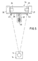
- FIG. 5 shows a vehicle 10 in the form of a golf cart with two driven wheels 20, 21 and a self-adjusting third support wheel 22 which can be pivoted about a vertical axis 23.
- the support wheel 22 is centered by a spring device when driving straight ahead. If the steering torque exerted on the support wheel 22 from the floor exceeds a certain limit value, the force of the spring device is overcome. Swiveling the support wheel out of the direction suitable for driving straight ahead is therefore only possible against a resetting spring force.
- the wheels 20, 21 can be driven individually by motors 24, 25. When driving straight ahead, the motors 24, 25 run at the same speeds. For cornering, they are driven at different speeds, with the differential speed determining the radius of the curve being driven.
- the ultrasonic units F1, F2 are receiving units that can only receive.
- the ultrasonic unit F3 serves as the transmitting unit. All three ultrasonic units F1, F2, F3 are attached to a common housing 26, which is designed as a crossbar to the vehicle 10.
- the housing 26 contains the electronic components of the first control unit 13.
- the entire evaluation unit is thus mounted as an independent structural unit in or on the housing 26.
- the transmitting ultrasound unit F3 and the receiving ultrasound units F1, F2 work together with the mobile control unit 14 which the previous golfer wears on the body.
- the first control unit and / or the second control unit takes a waiting state with reduced energy consumption on if it receives no signals from the other control unit for a predetermined period of time. This reduces energy consumption.
- the control unit 14 of the pacemaker is powered by a rechargeable battery which can be plugged into a slide-in box on the vehicle when it is at a standstill, in which it is charged by the vehicle battery.
- the first control unit contains an ultrasound unit that works as a transmitter with a first frequency f 1 and two further ultrasound units that work as a receiver on a second frequency f 2 that is different from f 1 .
- the mobile second control unit contains an ultrasound unit that works as a receiver on the first frequency f 1 and a further ultrasound unit that works as a transmitter on the frequency f 2 .
- the frequencies f 1 and f 2 are preferably between 20 and 50 kHz, in particular at 25 kHz and 40 kHz.
- the frequency can be adjusted on the ultrasound units of the first and second control units (e.g. to 23 kHz, 25 kHz or 27 kHz), so that golfers who accidentally meet in a flight can adjust the sequence controls of their vehicles to each other without interference.
- an additional, independently acting emergency stop device can be integrated in the first control unit.
- the emergency stop device measures the transit time of ultrasonic pulses from the first control unit a possible obstacle and the sound pulses reflected by the obstacle back to the first control unit. If this running time is below a predetermined minimum running time, the emergency stop device stops the vehicle.
Landscapes
- Engineering & Computer Science (AREA)
- Physics & Mathematics (AREA)
- Radar, Positioning & Navigation (AREA)
- Remote Sensing (AREA)
- Acoustics & Sound (AREA)
- Aviation & Aerospace Engineering (AREA)
- General Physics & Mathematics (AREA)
- Automation & Control Theory (AREA)
- Measurement Of Velocity Or Position Using Acoustic Or Ultrasonic Waves (AREA)
- Control Of Position, Course, Altitude, Or Attitude Of Moving Bodies (AREA)
- Steering Control In Accordance With Driving Conditions (AREA)
- Electronic Switches (AREA)
Applications Claiming Priority (2)
| Application Number | Priority Date | Filing Date | Title |
|---|---|---|---|
| DE19509320A DE19509320A1 (de) | 1995-03-15 | 1995-03-15 | Folgesteuerung für ein selbstfahrendes Fahrzeug |
| DE19509320 | 1995-03-15 |
Publications (3)
| Publication Number | Publication Date |
|---|---|
| EP0732641A2 true EP0732641A2 (fr) | 1996-09-18 |
| EP0732641A3 EP0732641A3 (fr) | 1997-05-02 |
| EP0732641B1 EP0732641B1 (fr) | 1999-09-29 |
Family
ID=7756706
Family Applications (1)
| Application Number | Title | Priority Date | Filing Date |
|---|---|---|---|
| EP96103943A Expired - Lifetime EP0732641B1 (fr) | 1995-03-15 | 1996-03-13 | Commande de poursuite pour véhicule sans conducteur |
Country Status (5)
| Country | Link |
|---|---|
| US (1) | US5810105A (fr) |
| EP (1) | EP0732641B1 (fr) |
| AT (1) | ATE185201T1 (fr) |
| CA (1) | CA2171696A1 (fr) |
| DE (2) | DE19509320A1 (fr) |
Cited By (16)
| Publication number | Priority date | Publication date | Assignee | Title |
|---|---|---|---|---|
| EP1435555A3 (fr) * | 2002-12-30 | 2004-10-27 | Samsung Electronics Co., Ltd. | Système de localisation pour un robot |
| EP1708065A3 (fr) * | 2005-03-31 | 2007-05-16 | Deere & Company | Procédé et système de suivi d'un véhicule de tête |
| US7479922B2 (en) | 2005-03-31 | 2009-01-20 | Deere & Company | Method and system for determining the location of a vehicle |
| WO2009037018A3 (fr) * | 2007-09-14 | 2009-06-11 | Bosch Gmbh Robert | Véhicule électrique sans conducteur |
| US7647177B2 (en) | 2005-03-31 | 2010-01-12 | Deere & Company | System and method for determining a position of a vehicle |
| US7653483B2 (en) | 2005-03-31 | 2010-01-26 | Deere & Company | System and method for determining a position of a vehicle |
| US7720598B2 (en) | 2005-03-31 | 2010-05-18 | Deere & Company | System and method for determining a position of a vehicle with compensation for noise or measurement error |
| US7860608B2 (en) | 2003-04-08 | 2010-12-28 | Samsung Electronics Co., Ltd. | Method and apparatus for generating and tracing cleaning trajectory of home cleaning robot |
| EP2014019A4 (fr) * | 2006-04-18 | 2011-08-24 | Metis Design Corp | Triangulation effectuée à l'aide de capteurs copositionnés |
| EP2062242B1 (fr) | 2006-09-14 | 2016-03-09 | Crown Equipment Corporation | Systèmes et procédés de commande à distance d'un véhicule de manutention de matériaux |
| FR3048406A1 (fr) * | 2016-03-07 | 2017-09-08 | Effidence | Robot autonome avec guidage en mode poussee |
| US10179723B2 (en) | 2006-09-14 | 2019-01-15 | Crown Equipment Corporation | Systems and methods of remotely controlling a materials handling vehicle |
| US10301155B2 (en) | 2008-12-04 | 2019-05-28 | Crown Equipment Corporation | Sensor configuration for a materials handling vehicle |
| US11429095B2 (en) | 2019-02-01 | 2022-08-30 | Crown Equipment Corporation | Pairing a remote control device to a vehicle |
| US11626011B2 (en) | 2020-08-11 | 2023-04-11 | Crown Equipment Corporation | Remote control device |
| US11641121B2 (en) | 2019-02-01 | 2023-05-02 | Crown Equipment Corporation | On-board charging station for a remote control device |
Families Citing this family (35)
| Publication number | Priority date | Publication date | Assignee | Title |
|---|---|---|---|---|
| DE4433750C1 (de) * | 1994-09-22 | 1995-12-14 | Bail Guenther | Führungssystem für ein selbstfahrendes Fahrzeug mit getrennter, mobiler Sendereinrichtung und Verfahren zum Steuern des Fahrzeugs |
| JP3504449B2 (ja) * | 1996-11-22 | 2004-03-08 | 本田技研工業株式会社 | 自動運転車 |
| DE19901953B4 (de) * | 1999-01-20 | 2014-02-06 | Robert Bosch Gmbh | Vorrichtung und Verfahren zur Stabilisierung eines Fahrzeuggespannes |
| US6327219B1 (en) | 1999-09-29 | 2001-12-04 | Vi&T Group | Method and system for directing a following device toward a movable object |
| WO2003096054A2 (fr) | 2002-05-10 | 2003-11-20 | Honda Giken Kogyo Kabushiki Kaisha | Suivi en temps reel d'une cible imprevisible parmi des obstacles inconnus |
| CN1981206B (zh) * | 2004-03-08 | 2012-06-13 | 株式会社Kt | 使用超声波的定位系统和用于控制其的方法 |
| FR2868560A1 (fr) * | 2004-04-02 | 2005-10-07 | Foissy Golf | Mobile motorise, notamment chariot pour sac de golf, comprenant des moyens de pilotage a distance |
| WO2006077605A1 (fr) * | 2005-01-20 | 2006-07-27 | O.M.G. S.R.L. | Voiturette automatique pour le transport d'objets, notamment sur des terrains de golf |
| US7062381B1 (en) * | 2005-08-30 | 2006-06-13 | Deere & Company | Method and system for determining relative position of mobile vehicles |
| WO2007132033A1 (fr) * | 2006-05-17 | 2007-11-22 | Smart Technology, S.A. | Système de détection, de guidage ou de suivi de dispositifs ou de personnes |
| EP2021823A1 (fr) * | 2006-05-17 | 2009-02-11 | Your Shadow Technologies Pty Ltd | Caddie de golf robotisé |
| IL200921A (en) * | 2009-09-14 | 2016-05-31 | Israel Aerospace Ind Ltd | A robotic carry system for infantry and useful methods for the above purpose |
| US8496078B2 (en) | 2011-01-29 | 2013-07-30 | GM Global Technology Operations LLC | Semi-autonomous vehicle providing cargo space |
| US8627908B2 (en) | 2011-01-29 | 2014-01-14 | GM Global Technology Operations LLC | Semi-autonomous vehicle providing an auxiliary power supply |
| US8789638B2 (en) | 2011-10-21 | 2014-07-29 | Ftr Systems, Inc. | Foldable cart with tracking arrangement |
| NL1039154C2 (en) * | 2011-11-07 | 2015-01-26 | Willem-Dirk Hendrik Udo | Target-following vehicle. |
| CA2885630C (fr) | 2012-09-19 | 2020-09-29 | Follow Inspiration Unipessoal, Lda. | Systeme de suivi automatique et son procede d'exploitation |
| US9114720B2 (en) | 2013-07-11 | 2015-08-25 | Delphi Technologies, Inc. | Vehicle positioning system for wireless charging stations |
| DE102013221263A1 (de) | 2013-10-21 | 2015-04-23 | Schaeffler Technologies Gmbh & Co. Kg | Autonom fahrendes Golfcaddy mit Ultraschallsensorik |
| DE102013221261A1 (de) | 2013-10-21 | 2015-04-23 | Schaeffler Technologies AG & Co. KG | Golftrolley mit mobilem RFID-Radar zur Positionsbestimmung |
| CN105022395B (zh) * | 2014-04-29 | 2018-05-11 | 世洋科技股份有限公司 | 前向跟随装置 |
| CN105022396B (zh) * | 2014-04-29 | 2018-03-06 | 世洋科技股份有限公司 | 前向暨左右侧向跟随装置及其跟随控制方法 |
| US20150327638A1 (en) * | 2014-05-15 | 2015-11-19 | Debashis Ghosh | Apparatus, system, and method of providing linkage between two or more objects such that they can passively track or follow one another |
| CN104991557A (zh) * | 2015-07-02 | 2015-10-21 | 深圳乐行天下科技有限公司 | 一种自主跟随小车及其系统 |
| CA2997160C (fr) * | 2015-10-16 | 2023-10-03 | Lemmings LLC | Chariot de golf robotise |
| CN105629241A (zh) * | 2015-12-22 | 2016-06-01 | 浙江大学 | 一种基于分体超声结合射频的机器人定位方法 |
| DE102016200813A1 (de) * | 2016-01-21 | 2017-07-27 | Robert Bosch Gmbh | Verfahren zur Bestimmung einer Fahrzeugposition |
| CN108885449A (zh) * | 2016-02-09 | 2018-11-23 | 福特全球技术公司 | 用于自主车辆跟随对象的设备和方法 |
| FR3048148B1 (fr) * | 2016-02-22 | 2018-12-07 | Universite Blaise Pascal | Localisation d'une cible pour vehicule suiveur |
| CN106114595B (zh) * | 2016-08-17 | 2018-02-27 | 广东工业大学 | 一种具有自动跟随功能的移动设备 |
| DE102016215458A1 (de) * | 2016-08-18 | 2018-02-22 | Robert Bosch Gmbh | Radvorrichtung, als auch Fahrzeug mit solch einer Radvorrichtung und Verfahren zum Ansteuern der Radvorrichtung |
| CN107831759B (zh) * | 2016-09-16 | 2022-09-27 | 福特全球技术公司 | 具有自动束缚功能的运送系统 |
| DE102017200737A1 (de) | 2017-01-18 | 2018-07-19 | Robert Bosch Gmbh | Manuell bewegbares und motorisiertes Transportvehikel |
| US10852722B2 (en) * | 2019-04-03 | 2020-12-01 | Ching MENG | Following operation system |
| DE102024133914A1 (de) * | 2024-11-19 | 2026-05-21 | Bomag Gmbh | Verfahren zum Bedienen einer selbstfahrenden Straßenbaumaschine und System zum Betrieb einer Straßenbaumaschine |
Citations (1)
| Publication number | Priority date | Publication date | Assignee | Title |
|---|---|---|---|---|
| DE4326016C1 (de) | 1993-08-03 | 1994-09-15 | Bail Guenther | Selbstfahrendes Fahrzeug, vorzugsweise Golfwagen |
Family Cites Families (23)
| Publication number | Priority date | Publication date | Assignee | Title |
|---|---|---|---|---|
| US3662328A (en) * | 1969-04-30 | 1972-05-09 | David Spivak | Apparatus for determining the proximity of moving vehicles |
| US3742507A (en) * | 1970-09-10 | 1973-06-26 | J Pirre | Automatic golf bag cart |
| US3720281A (en) * | 1971-02-16 | 1973-03-13 | J Frownfelter | Remotely controlled vehicle |
| US3812929A (en) * | 1971-07-26 | 1974-05-28 | Citation Mfg Co Inc | Self-propelled golf cart |
| US3976151A (en) * | 1971-07-26 | 1976-08-24 | Citation Manufacturing Company, Inc. | Self-propelled golf cart |
| US3777305A (en) * | 1972-04-10 | 1973-12-04 | Us Navy | Ultrasonic angle measurement system |
| CA1017827A (fr) * | 1974-02-18 | 1977-09-20 | Pierre Beaurain | Installation et procede de detection de presence a grande resolution |
| US4109186A (en) * | 1974-04-17 | 1978-08-22 | Gettig Engineering & Manufacturing Co., Inc. | Self-propelled golf cart |
| US4136394A (en) * | 1977-09-23 | 1979-01-23 | Joseph Jones | Golf yardage indicator system |
| GB2038132A (en) * | 1978-11-14 | 1980-07-16 | Burling G T | Distance indicating system |
| DE3015955A1 (de) * | 1980-04-25 | 1981-11-05 | Robert Bosch Gmbh, 7000 Stuttgart | Sicherheitsvorrichtung fuer fahrzeuge mit fremdkraft-lenkanlagen |
| SE456372B (sv) * | 1984-04-06 | 1988-09-26 | Bt Ind Ab | Forfarande for att hos en operatorlos maskin detektera hinder |
| DE3534044A1 (de) * | 1985-09-24 | 1987-04-16 | Krauss Maffei Ag | Schleppfahrzeug fuer flugzeuge |
| GB8621105D0 (en) * | 1986-09-01 | 1986-10-08 | Kramer D C | Remotely-controlled vehicle |
| US5050134A (en) * | 1990-01-19 | 1991-09-17 | Science Accessories Corp. | Position determining apparatus |
| JP2817327B2 (ja) * | 1990-03-13 | 1998-10-30 | トヨタ自動車株式会社 | 車両用追従走行制御装置 |
| JP2583641B2 (ja) * | 1990-05-18 | 1997-02-19 | 日産自動車株式会社 | 走行制御方法 |
| US5420794A (en) * | 1993-06-30 | 1995-05-30 | James; Robert D. | Automated highway system for controlling the operating parameters of a vehicle |
| GB9323316D0 (en) * | 1993-11-11 | 1994-01-05 | Crowe Gordon M | Motorized carrier |
| US5504477A (en) * | 1993-11-15 | 1996-04-02 | Wybron, Inc. | Tracking system |
| US5517098A (en) * | 1994-05-09 | 1996-05-14 | Dong; Dawei | Automatic tracking mobile platform |
| DE4433957A1 (de) * | 1994-09-23 | 1996-03-28 | Mayser Gmbh & Co | Verfahren zur Ultraschall-Hinderniserkennung |
| IL112981A (en) * | 1995-03-13 | 1999-03-12 | Gilon Shmuel | Collision avoidance detector |
-
1995
- 1995-03-15 DE DE19509320A patent/DE19509320A1/de not_active Withdrawn
-
1996
- 1996-03-13 DE DE59603195T patent/DE59603195D1/de not_active Expired - Fee Related
- 1996-03-13 EP EP96103943A patent/EP0732641B1/fr not_active Expired - Lifetime
- 1996-03-13 CA CA002171696A patent/CA2171696A1/fr not_active Abandoned
- 1996-03-13 US US08/614,654 patent/US5810105A/en not_active Expired - Fee Related
- 1996-03-13 AT AT96103943T patent/ATE185201T1/de not_active IP Right Cessation
Patent Citations (1)
| Publication number | Priority date | Publication date | Assignee | Title |
|---|---|---|---|---|
| DE4326016C1 (de) | 1993-08-03 | 1994-09-15 | Bail Guenther | Selbstfahrendes Fahrzeug, vorzugsweise Golfwagen |
Cited By (21)
| Publication number | Priority date | Publication date | Assignee | Title |
|---|---|---|---|---|
| US7970491B2 (en) | 2002-12-30 | 2011-06-28 | Samsung Electronics Co., Ltd. | Robot localization system |
| EP1435555A3 (fr) * | 2002-12-30 | 2004-10-27 | Samsung Electronics Co., Ltd. | Système de localisation pour un robot |
| US7860608B2 (en) | 2003-04-08 | 2010-12-28 | Samsung Electronics Co., Ltd. | Method and apparatus for generating and tracing cleaning trajectory of home cleaning robot |
| EP1708065A3 (fr) * | 2005-03-31 | 2007-05-16 | Deere & Company | Procédé et système de suivi d'un véhicule de tête |
| US7479922B2 (en) | 2005-03-31 | 2009-01-20 | Deere & Company | Method and system for determining the location of a vehicle |
| US7593811B2 (en) | 2005-03-31 | 2009-09-22 | Deere & Company | Method and system for following a lead vehicle |
| US7647177B2 (en) | 2005-03-31 | 2010-01-12 | Deere & Company | System and method for determining a position of a vehicle |
| US7653483B2 (en) | 2005-03-31 | 2010-01-26 | Deere & Company | System and method for determining a position of a vehicle |
| US7720598B2 (en) | 2005-03-31 | 2010-05-18 | Deere & Company | System and method for determining a position of a vehicle with compensation for noise or measurement error |
| EP2014019A4 (fr) * | 2006-04-18 | 2011-08-24 | Metis Design Corp | Triangulation effectuée à l'aide de capteurs copositionnés |
| EP2062242B1 (fr) | 2006-09-14 | 2016-03-09 | Crown Equipment Corporation | Systèmes et procédés de commande à distance d'un véhicule de manutention de matériaux |
| US10179723B2 (en) | 2006-09-14 | 2019-01-15 | Crown Equipment Corporation | Systems and methods of remotely controlling a materials handling vehicle |
| WO2009037018A3 (fr) * | 2007-09-14 | 2009-06-11 | Bosch Gmbh Robert | Véhicule électrique sans conducteur |
| US10301155B2 (en) | 2008-12-04 | 2019-05-28 | Crown Equipment Corporation | Sensor configuration for a materials handling vehicle |
| FR3048406A1 (fr) * | 2016-03-07 | 2017-09-08 | Effidence | Robot autonome avec guidage en mode poussee |
| US11429095B2 (en) | 2019-02-01 | 2022-08-30 | Crown Equipment Corporation | Pairing a remote control device to a vehicle |
| US11500373B2 (en) | 2019-02-01 | 2022-11-15 | Crown Equipment Corporation | On-board charging station for a remote control device |
| US11641121B2 (en) | 2019-02-01 | 2023-05-02 | Crown Equipment Corporation | On-board charging station for a remote control device |
| US12308681B2 (en) | 2019-02-01 | 2025-05-20 | Crown Equipment Corporation | On-board charging station for a remote control device |
| US12504752B2 (en) | 2019-02-01 | 2025-12-23 | Crown Equipment Corporation | On-board charging station for a remote control device |
| US11626011B2 (en) | 2020-08-11 | 2023-04-11 | Crown Equipment Corporation | Remote control device |
Also Published As
| Publication number | Publication date |
|---|---|
| DE19509320A1 (de) | 1996-09-19 |
| DE59603195D1 (de) | 1999-11-04 |
| EP0732641A3 (fr) | 1997-05-02 |
| US5810105A (en) | 1998-09-22 |
| CA2171696A1 (fr) | 1996-09-16 |
| EP0732641B1 (fr) | 1999-09-29 |
| ATE185201T1 (de) | 1999-10-15 |
Similar Documents
| Publication | Publication Date | Title |
|---|---|---|
| EP0732641B1 (fr) | Commande de poursuite pour véhicule sans conducteur | |
| DE102009043060B4 (de) | System von mobilen Robotern mit einer Basisstation sowie Verfahren zum Betreiben des Systems | |
| DE3518613C2 (de) | Hindernis-Erfassungssystem | |
| EP0970390B1 (fr) | Procede de determination de l'ecart vertical entre un objet et un dispositif a position variable | |
| DE69913150T2 (de) | Robotersystem | |
| EP0610702A2 (fr) | Dispositif pour faciliter la marche arrière et l'attache des remorques aux véhicules automobiles | |
| EP0192172A1 (fr) | Dispositif pour déterminer le déroulement du mouvement pendant les courses à pied | |
| DE2143623B2 (de) | Ferngesteuertes fahrzeug, insbesondere koecherwagen fuer golfschlaeger | |
| EP0319700A1 (fr) | Aspirateur de poussières mobile | |
| EP0378528B1 (fr) | Procede pour guider un vehicule automoteur et vehicule automoteur | |
| DE4326016C1 (de) | Selbstfahrendes Fahrzeug, vorzugsweise Golfwagen | |
| EP1730616B1 (fr) | Système de traitement de surfaces | |
| DE3001146A1 (de) | Automatische fuehrungsvorrichtung fuer ein flurfoefderzeug | |
| DE102005004508A1 (de) | Vorrichtung zur gleichmäßigen Beschickung von Arbeitsmaschinen | |
| EP0782723A1 (fr) | Systeme de guidage pour vehicule autopropulse a dispositif emetteur mobile separe et procede de commande du vehicule | |
| DE4313054A1 (de) | Fahrzeug-Manövrierhilfe | |
| DE3910537C2 (fr) | ||
| DE3315051C2 (de) | Verfahren zum selbsttätigen führerlosen Betrieb von Fahrzeugen | |
| EP3168183B1 (fr) | Procédé de commande d'un chariot de manutention et chariot de manutention correspondant | |
| DE102007036231A1 (de) | Verfahren und System zum Steuern des Fahrens eines mobilen Geräts in Bezug auf ein stationäres Gerät, insbesondere eines akkumulatorbetriebenen Staubsammelroboters in Bezug auf eine Akkumulator-Ladestation | |
| DE2704852C2 (de) | Anordnung von Vorrichtungen, insbesondere mit einer Anzeige- bzw. Steuervorrichtung zum Führen eines Fahrzeuges | |
| DE102017216349A1 (de) | Transportsystem mit automatischer Folgefunktion sowie Steuerungsverfahren | |
| EP3918912A1 (fr) | Agencement de commande d'un appareil de travail autonome | |
| EP1899536B1 (fr) | Systeme de plaques vibrantes | |
| DE102007036164A1 (de) | Verfahren zur Bestimmung des Fahrwinkels eines fahrbaren Geräts in Bezug auf einen vor diesem befindlichen Wandbereich sowie nach diesem Verfahren betriebenes fahrbares Gerät, insbesondere Staubsammelroboter |
Legal Events
| Date | Code | Title | Description |
|---|---|---|---|
| PUAI | Public reference made under article 153(3) epc to a published international application that has entered the european phase |
Free format text: ORIGINAL CODE: 0009012 |
|
| AK | Designated contracting states |
Kind code of ref document: A2 Designated state(s): AT BE CH DE DK ES FR GB GR IE IT LI NL PT SE |
|
| PUAL | Search report despatched |
Free format text: ORIGINAL CODE: 0009013 |
|
| AK | Designated contracting states |
Kind code of ref document: A3 Designated state(s): AT BE CH DE DK ES FR GB GR IE IT LI NL PT SE |
|
| 17P | Request for examination filed |
Effective date: 19971024 |
|
| GRAG | Despatch of communication of intention to grant |
Free format text: ORIGINAL CODE: EPIDOS AGRA |
|
| 17Q | First examination report despatched |
Effective date: 19981111 |
|
| GRAG | Despatch of communication of intention to grant |
Free format text: ORIGINAL CODE: EPIDOS AGRA |
|
| GRAH | Despatch of communication of intention to grant a patent |
Free format text: ORIGINAL CODE: EPIDOS IGRA |
|
| GRAH | Despatch of communication of intention to grant a patent |
Free format text: ORIGINAL CODE: EPIDOS IGRA |
|
| GRAA | (expected) grant |
Free format text: ORIGINAL CODE: 0009210 |
|
| AK | Designated contracting states |
Kind code of ref document: B1 Designated state(s): AT BE CH DE DK ES FR GB GR IE IT LI NL PT SE |
|
| PG25 | Lapsed in a contracting state [announced via postgrant information from national office to epo] |
Ref country code: SE Free format text: THE PATENT HAS BEEN ANNULLED BY A DECISION OF A NATIONAL AUTHORITY Effective date: 19990929 Ref country code: NL Free format text: LAPSE BECAUSE OF FAILURE TO SUBMIT A TRANSLATION OF THE DESCRIPTION OR TO PAY THE FEE WITHIN THE PRESCRIBED TIME-LIMIT Effective date: 19990929 Ref country code: GR Free format text: LAPSE BECAUSE OF NON-PAYMENT OF DUE FEES Effective date: 19990929 Ref country code: ES Free format text: THE PATENT HAS BEEN ANNULLED BY A DECISION OF A NATIONAL AUTHORITY Effective date: 19990929 |
|
| REF | Corresponds to: |
Ref document number: 185201 Country of ref document: AT Date of ref document: 19991015 Kind code of ref document: T |
|
| REG | Reference to a national code |
Ref country code: CH Ref legal event code: EP |
|
| REF | Corresponds to: |
Ref document number: 59603195 Country of ref document: DE Date of ref document: 19991104 |
|
| REG | Reference to a national code |
Ref country code: IE Ref legal event code: FG4D Free format text: GERMAN |
|
| ITF | It: translation for a ep patent filed | ||
| ET | Fr: translation filed | ||
| PG25 | Lapsed in a contracting state [announced via postgrant information from national office to epo] |
Ref country code: PT Free format text: LAPSE BECAUSE OF FAILURE TO SUBMIT A TRANSLATION OF THE DESCRIPTION OR TO PAY THE FEE WITHIN THE PRESCRIBED TIME-LIMIT Effective date: 19991229 Ref country code: DK Free format text: LAPSE BECAUSE OF FAILURE TO SUBMIT A TRANSLATION OF THE DESCRIPTION OR TO PAY THE FEE WITHIN THE PRESCRIBED TIME-LIMIT Effective date: 19991229 |
|
| GBT | Gb: translation of ep patent filed (gb section 77(6)(a)/1977) |
Effective date: 19991214 |
|
| NLV1 | Nl: lapsed or annulled due to failure to fulfill the requirements of art. 29p and 29m of the patents act | ||
| PG25 | Lapsed in a contracting state [announced via postgrant information from national office to epo] |
Ref country code: AT Free format text: LAPSE BECAUSE OF NON-PAYMENT OF DUE FEES Effective date: 20000313 |
|
| PG25 | Lapsed in a contracting state [announced via postgrant information from national office to epo] |
Ref country code: BE Free format text: LAPSE BECAUSE OF NON-PAYMENT OF DUE FEES Effective date: 20000331 |
|
| PLBE | No opposition filed within time limit |
Free format text: ORIGINAL CODE: 0009261 |
|
| STAA | Information on the status of an ep patent application or granted ep patent |
Free format text: STATUS: NO OPPOSITION FILED WITHIN TIME LIMIT |
|
| 26N | No opposition filed | ||
| BERE | Be: lapsed |
Owner name: TECHNOLOGIETRANSFER-ANSTALT TETRA Effective date: 20000331 |
|
| REG | Reference to a national code |
Ref country code: IE Ref legal event code: FD4D |
|
| PGFP | Annual fee paid to national office [announced via postgrant information from national office to epo] |
Ref country code: FR Payment date: 20010319 Year of fee payment: 6 |
|
| PGFP | Annual fee paid to national office [announced via postgrant information from national office to epo] |
Ref country code: GB Payment date: 20010327 Year of fee payment: 6 |
|
| PGFP | Annual fee paid to national office [announced via postgrant information from national office to epo] |
Ref country code: DE Payment date: 20010430 Year of fee payment: 6 |
|
| REG | Reference to a national code |
Ref country code: GB Ref legal event code: IF02 |
|
| PGFP | Annual fee paid to national office [announced via postgrant information from national office to epo] |
Ref country code: CH Payment date: 20020207 Year of fee payment: 7 |
|
| PG25 | Lapsed in a contracting state [announced via postgrant information from national office to epo] |
Ref country code: GB Free format text: LAPSE BECAUSE OF NON-PAYMENT OF DUE FEES Effective date: 20020313 |
|
| PG25 | Lapsed in a contracting state [announced via postgrant information from national office to epo] |
Ref country code: DE Free format text: LAPSE BECAUSE OF NON-PAYMENT OF DUE FEES Effective date: 20021001 |
|
| GBPC | Gb: european patent ceased through non-payment of renewal fee |
Effective date: 20020313 |
|
| PG25 | Lapsed in a contracting state [announced via postgrant information from national office to epo] |
Ref country code: FR Free format text: LAPSE BECAUSE OF NON-PAYMENT OF DUE FEES Effective date: 20021129 |
|
| REG | Reference to a national code |
Ref country code: FR Ref legal event code: ST |
|
| PG25 | Lapsed in a contracting state [announced via postgrant information from national office to epo] |
Ref country code: LI Free format text: LAPSE BECAUSE OF NON-PAYMENT OF DUE FEES Effective date: 20030331 Ref country code: CH Free format text: LAPSE BECAUSE OF NON-PAYMENT OF DUE FEES Effective date: 20030331 |
|
| REG | Reference to a national code |
Ref country code: CH Ref legal event code: PL |
|
| PG25 | Lapsed in a contracting state [announced via postgrant information from national office to epo] |
Ref country code: IT Free format text: LAPSE BECAUSE OF NON-PAYMENT OF DUE FEES;WARNING: LAPSES OF ITALIAN PATENTS WITH EFFECTIVE DATE BEFORE 2007 MAY HAVE OCCURRED AT ANY TIME BEFORE 2007. THE CORRECT EFFECTIVE DATE MAY BE DIFFERENT FROM THE ONE RECORDED. Effective date: 20050313 |