EP0732838A2 - Annuleur d'écho acoustique - Google Patents
Annuleur d'écho acoustique Download PDFInfo
- Publication number
- EP0732838A2 EP0732838A2 EP96301651A EP96301651A EP0732838A2 EP 0732838 A2 EP0732838 A2 EP 0732838A2 EP 96301651 A EP96301651 A EP 96301651A EP 96301651 A EP96301651 A EP 96301651A EP 0732838 A2 EP0732838 A2 EP 0732838A2
- Authority
- EP
- European Patent Office
- Prior art keywords
- filter
- echo
- signal
- sound generated
- sound
- Prior art date
- Legal status (The legal status is an assumption and is not a legal conclusion. Google has not performed a legal analysis and makes no representation as to the accuracy of the status listed.)
- Granted
Links
Images


Classifications
-
- H—ELECTRICITY
- H04—ELECTRIC COMMUNICATION TECHNIQUE
- H04M—TELEPHONIC COMMUNICATION
- H04M9/00—Arrangements for interconnection not involving centralised switching
- H04M9/08—Two-way loud-speaking telephone systems with means for conditioning the signal, e.g. for suppressing echoes for one or both directions of traffic
- H04M9/082—Two-way loud-speaking telephone systems with means for conditioning the signal, e.g. for suppressing echoes for one or both directions of traffic using echo cancellers
-
- H—ELECTRICITY
- H04—ELECTRIC COMMUNICATION TECHNIQUE
- H04B—TRANSMISSION
- H04B7/00—Radio transmission systems, i.e. using radiation field
- H04B7/015—Reducing echo effects
Definitions
- This invention relates to an echo removing apparatus and, more particularly, to an echo removing apparatus for reducing the echo caused by sound generated "turning round" or leaking from a speaker to a microphone of a small-sized sound generated communication terminal, such as a portable telephone.
- an echo removing apparatus or an echo canceller shown for example in Fig.1 is employed.
- a terminal 11 receives a speaker output signal x(k) transmitted from a communication partner to a speaker 12, where k denotes a sample number or a time position of discrete signals.
- a microphone input signal y(k) collected by a microphone 13 and thereby converted into an electrical signal, is supplied along with a pseudo echo signal supplied from a filter circuit 15 to a subtractor 14.
- the subtractor subtracts the pseudo echo signal supplied from the microphone input signal to form a resultant echo-reduced signal or a residual echo signal e(k) which is supplied to an input terminal 16.
- the speaker 12 and the microphone 13 are usually arranged close to each other as a telephone handset.
- a so-called finite impluse response (FIR) filter is employed for the adaptive filter 15.
- the filter coefficients or tap coefficients are set for minimizing the error signal(k).
- the adaptive filter 15 filters the input signal, that is the speaker output signal x(k), for estimating the echo signal for generating the pseudo echo signal.
- This pseudo echo signal is provided to the subtractor 14 where the pseudo echo signal is subtracted from the microphone input signal y(k) to derive the residual echo signal or error signal e(k).
- the tap coefficient ⁇ b k (i) ⁇ of the adaptive filter 15, where i 1, 2, ..., N-1, is updated, by a suitable algorithm, such as a least mean square (LMS) algorithm, learning identification method or a recursive least square (RLS) algorithm, for minimizing the time average of the power of the error signal e(k) of the equation (2), that is, E[ e k 2 ] where E[] is an expected value or a mean value of the value within the brackets [] and
- the tap coefficients of N taps of the adaptive filter 15 are equivalent to estimated values of echo characteristics between the speaker 12 and the microphone 13.
- the frequency characteristics of the residual echo are left in the low frequency range, even although the echo characteristics can be estimated partially with high accuracy by the adaptive filter 15, thus raising difficulties in effectively cancelling the echo from sound generated input signals containing strong low-frequency components.
- Fig.2A shows the impulse response of the echo signals in association with the respective taps of the FIR filter.
- Fig.2B shows the impulse response of the residual echo signal obtained on subtracting the pseudo echo signal estimated by 20-tap FIR adaptive filter. It is seen from Figs.2A and 2B that the impulse response of the residual echo signal corresponding to 20 taps has been removed.
- Fig.3 shows, in association with Figs.2A and 2B, a spectral curve a of the echo signal and a spectral curve b of the residual echo signal produced on subtracting the estimated echo signal supplied from the 20-tap FIR adaptive filter.
- the frequency characteristics of the residual echo characteristics are left in a region from 500 Hz to 1 kHz where the energy of sound generated signal would be concentrated to a larger extent.
- an echo removing apparatus for removing the echo produced by sound generated from sound generating means being turned round to sound collecting means arranged in proximity to said sound generating means, comprising:
- the subtraction means may subtract the pseudo echo signal supplied from an output signal of the first characteristics conversion means.
- a second characteristics conversion means may also be provided in the echo removing apparatus for converting frequency characteristics of an output signal of the subtraction means on the frequency axis.
- the second characteristics conversion means is provided in the echo removing apparatus for converting frequency characteristics of an output signal of the filter means on the frequency axis.
- An output signal of the second characteristics conversion means is provided as a pseudo echo signal to the subtraction means for subtraction from sound generated collection signal supplied from sound generated collection means.
- the echo cancellation characteristics may be improved even with a smaller number of taps of the filter means.
- a smaller processing volume suffices for achieving the echo cancellation characteristics comparable to those of a conventional echo removing apparatus.
- Fig.1 is a schematic block diagram showing the structure of a conventional echo removing apparatus.
- Figs.2A and 2B are graphs showing the response to the tap numbers of an FIR adaptive filter for echo estimation.
- Fig.3 is a graph showing a spectral curve for echo signals and a spectral curve for residual echo signals.
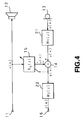
- Fig.4 is a schematic block diagram showing a basic structure of an echo removing apparatus according to the present invention.
- Fig.5 is a schematic block diagram showing another basic structure of an echo removing apparatus according to the present invention.
- Fig.6 is a block diagram showing an FIR adaptive filter employed as a filter for converting characteristics of the echo removing apparatus according to the present invention.
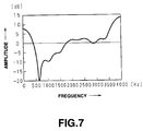
- Fig.7 is a graph showing frequency characteristics of a fixed-coefficient FIR filter employed as a filter for converting characteristics of the echo removing apparatus according to the present invention.
- Fig.8 is a block diagram showing a fixed-coefficient FIR filter employed as a filter for converting characteristics of the echo removing apparatus according to the present invention.
- Fig.9 is a block diagram showing an echo removing apparatus according to the present invention on the decoder side of sound generated encoding system.
- Fig.10 is a graph showing the relation between the pitch period of the input signal and the number of filter taps.
- Fig.11 is a graph illustrating input signal power fluctuations in case of a smaller number of filter taps.
- Fig.12 is a graph showing the amount of echo cancellation and the number of filter taps.
- Fig.4 schematically shows an embodiment of an echo removing apparatus according to the present invention.
- a speaker output signal x(k) as a generated sound signal transmitted from a communication partner to a speaker 12, as sound generating means.
- a microphone input signal y(k) collected by a microphone 13, arranged as sound collection means close to the speaker 12 as sound generating means, and thereby converted into an electrical signal, is converted by a characteristics conversion filter 21, as first characteristics conversion means, into a signal u(k), which is supplied to an echo-removing subtractor 14.
- the subtractor 14 subtracts the pseudo echo signal supplied from the adaptive filter 15 to form an echo-reduced signal or a residual echo signal e(k).
- This signal is filtered by a characteristics conversion filter 22 as second characteristics conversion means to form a signal z(k) which is outputted at a terminal 16 as an echo-reduced output signal.
- the speaker 12 and the microphone 13 are usually arranged close to each other as a handset of a portable telephone.
- the adaptive filter 15 may, for example, be a finite impulse response (FIR) filter having its filter coefficients or tap coefficients selected by adaptive processing which will minimize a time average value of the power of the error signal e(k).
- the adaptive filter 15 receives the input signal supplied from the terminal 11, which is the speaker output signal x(k), as a tap input, and outputs a pseudo echo signal, which estimates the signal u(k) from the characteristics conversion filter 21, to the subtractor 14.
- FIR finite impulse response
- the first characteristics conversion filter 21 converts characteristics of the input signal, that is the microphone input signal y(k), on the frequency axis.
- the filter 21 preferably has the characteristics of equalizing or whitening the input sound generated signal on the frequency axis.
- a speaker output signal x(k) as a generated sound signal transmitted from a communication partner is supplied via a terminal 11 to a speaker 12 as sound generating means.
- a microphone input signal y(k) collected by a microphone 13, arranged as sound collection means close to the speaker 12 as sound generating means, and thereby converted into an electrical signal, is supplied to a characteristics conversion filter 31, as first characteristics conversion means, and to an echo-removing subtractor 14.
- the microphone input signal y(k) is filtered by a characteristics conversion filter 31 into a signal u(k) which is supplied to a subtractor 33 where the adaptive filter output signal supplied from the adaptive filter 15 is subtracted from the signal u(k) to form an error signal e(k).
- This error signal e(k) is supplied to a characteristic conversion filter 32 as the second characteristic conversion means where it is filtered to form a pseudo echo signal which is provided to the subtractor 14.
- the subtractor 14 subtracts the pseudo echo signal supplied from the microphone input signal y(k) to form an echo-reduced output signal z(k) which is outputted at a terminal 16.
- the speaker 12 and the microphone 13 are usually arranged close to each other as a handset of a portable telephone.
- the adaptive filter 15 may, for example, be a finite impulse response (FIR) filter having its filter coefficients or tap coefficients selected by adaptive processing which will minimize a time average value of the power of the error signal e(k).
- FIR finite impulse response
- the adaptive filter 15 receives an input signal at the terminal 11, which is the speaker output signal x(k), as a tap input, and outputs a pseudo echo signal, which estimates the signal u(k) from the characteristics conversion filter 21, to a subtractor 30.
- the first characteristics conversion filter 31 converts characteristics of the input signal, that is the microphone input signal y(k), on the frequency axis.
- the filter 31 preferably has the characteristics of equalizing or whitening the input sound generated signal on the frequency axis.
- the processing which is equivalent to the basic structure shown in Fig.4 is performed by a signal flow different from that of Fig.4.
- the processing is realized with a digital signal processor (DSP)
- DSP digital signal processor
- the gain of the transfer function W 1 (z) of the first characteristic conversion filter 31 may conveniently be controlled for effectively scaling the filter coefficients without distorting sound generated of the speaker talking at the microphone.
- Fig.6 shows a filter modified from the first characteristics conversion filter 21 of Fig.4, in which filter coefficients of a transfer function W 1 (z) of the first characteristics conversion filter 21 have been adaptively changed so that the filter operates as an inverse filter or a whitening filter with respect to the residual echo signal or as the error signal e(k).
- the transfer function W 2 (z) of the second characteristic conversion filter is set to 1/W 1 (z).
- a filter 42 is an infinite impulse filter (IIR) having its transfer function W 2 (z), equivalent to the transfer function W 2 (z) of the second characteristic conversion filter 22 of Fig.4, represented by:
- IIR infinite impulse filter
- the filtering by the FIR adaptive filter 41 is performed to derive a signal u(k) shown by the equation (6):
- the adaptive filter 15 receives the speaker output signal x(k), that is an input signal supplied from the terminal 11, as a tap input signal, and generates an adaptive filter output signal given by the equation:
- the error signal e(k) from the subtractor 14 is filtered by the IIR filter 42 to give an echo-reduced output signal z(k) given by the equation: which signal z(k) is outputted at the terminal 16.
- optimum echo cancellation characteristics may be achieved even in case of a small number of taps of the adaptive filter 15, while the processing volume needs to be increased only to a lesser extent.
- the filters of variable coefficients such as the FIR adaptive filter 41 or the IIR filter 42, configured for characteristics conversion, may be replaced by filters of fixed coefficients.
- Fig.7 shows an example of frequency characteristics of an FIR filter employed as first characteristics conversion means
- Fig.8 shows a schematic structure of an echo removing apparatus employing a characteristics conversion filter of a fixed coefficient. That is, typical frequency characteristics of the fixed coefficient FIR filter 51 as the first characteristics conversion means of Fig.8 is shown in Fig.7.
- an FIR filter 51 operating as an inverse filter or a whitening filter with respect to the residual echo signal or the error signal E(k) is employed as a filter equivalent to the first characteristic conversion filter 21 of Fig.1.
- a filter 52 corresponding to the transfer function W 2 (z) of the second characteristic conversion filter 2 of Fig.4, is an IIR filter whose transfer function W 2 (z) is given by the equation:
- the microphone input signal y(k) from the microphone 13 is filtered by the FIR adaptive filter 41 to derive a signal u(k) as shown by the equation (13):
- the adaptive filter 15 receives the speaker output signal, which is the input signal at the terminal 11, as a tap input signal, and generates an adaptive filter output signal given by:
- This error signal e(k) is filtered by the above IIR filter 42 to produce an echo-reduced output signal z(k) represented by
- the tap coefficient ⁇ b k (i) ⁇ of the adaptive filter 15 is updated by a suitable adaptive algorithm for minimizing the time average of the power of the error signal e(k), as in the illustrative embodiment shown in Fig.6.
- the structure and the processing volume may be decreased, as compared to the embodiment shown in Fig.6, in an amount corresponding to the adaptive processing of the characteristics conversion filter which may be omitted.
- the coefficients of the characteristics conversion filter may be determined on the basis of sound generated encoding parameters.
- Fig.9 shows an illustrative embodiment of an echo removing apparatus employed on the decoder side of sound generated encoding system.
- filters 61, 62 are equivalent to the first characteristic conversion filter 21 and to the second characteristic conversion filter 22 of Fig.1, respectively.
- To an input terminal 63 are supplied parameters characteristic of sound generated and encoded sound generated signals encoded and transmitted by the encoder and received by the receiver. These encoded sound generated signals are decoded by sound generated decoder 64 into a speaker output signal x(k) as the generated sound signal or sound generated signal which is sent to the speaker 12 as sound generating means.
- the parameters characteristic of sound generated such as vocal tract parameters or ⁇ -parameters of VSELP, supplied from the input terminal 63, are sent to a parameter converter 65 where they are converted into filter coefficients of the characteristics conversion filters 61, 62 for updating the filter coefficients of the filters 61, 62.
- the coefficients of the filter 61 equivalent to the first characteristic conversion filter are converted into coefficients which will enable the whitening filter coefficients of whitening the input signals to be produced.
- the coefficients of the filter 62 are converted into coefficients which will enable opposite filter characteristics to be produced.
- the microphone input signal y(k) from the microphone 13 is filtered by the filter 61 to derive the signal u(k) represented by the equation (17):
- the adaptive filter 15 receiving the speaker output signal x(k) from sound generated decoder 64 as the tap input signal, produces an adaptive filter output given by:
- the error signal e(k) from the subtractor 14 is filtered by the filter 62 to give an error-reduced signal z(k) represented by the equation: which is outputted at the terminal 16.
- the tap coefficient ⁇ b k (i) ⁇ is updated by adaptive processing by any suitable adaptive algorithm for minimizing the time average of the power of the error signal e(k) from the subtractor 14.
- the filter coefficients of the filters 61 and 62 are converted and updated into those of the whitening filter or the inverse filters thereof by a parameter converter 65.
- the smoothed input signal power value is employed as the tap input signal power of the equation employed for tap coefficients or filter coefficients of the learning identification method for producing echo removing characteristics or echo cancellation characteristics even in case the number of taps is smaller than sound generated pitch period.
- the denominator of the equation (21), that is the tap input signal power or the square sum, as calculated by the equation (22), is significantly fluctuated, as shown in Fig.ll.
- the square sum which is the power in the domain a corresponding to the tap length of Fig.10, becomes larger, while the power in the domain b becomes smaller. If the input signal power or the square sum is fluctuated in this manner, the tap coefficient updated by the equation (21) the tap coefficients updated by the equation (21) are fluctuated, thus occasionally making it impossible to produce stable echo removing or suppression characteristics.
- the denominator of the equation (21), that is the input signal power or the square sum calculated by the equation (22), is replaced by a power value smoothed by a suitable method, that is a smoothed value of the input signal power P x (k), for realizing stable echo removing or suppression characteristics.
- ⁇ is a constant such that 0 ⁇ ⁇ ⁇ 1, with the corresponding time constant being 1/(1 - ⁇ ).
- the smoothed power that is the smoothed input signal power P x (k)
- variations in the filter coefficients or tap coefficients may be suppressed for achieving stable echo removing or suppression characteristics.
- the number of taps of the FIR filter, as the adaptive filter 15, is taken on the abscissa and the amount of echo cancellation ERLE is taken on the ordinate.
- the echo canceller output voltage of the equation (26) is the power of the signal z(k) taken out at the terminal 16, while the microphone input voltage is the power of the microphone input signal y(k) from the microphone 13.
- a curve a stands for the amount of echo cancellation in case of using a characteristic conversion filter FIR filter 51, such as a fixed coefficient filter with the number of taps M equal to 12, and a filter 52 functioning an its inverse filter, while a curve b stands for the amount of echo cancellation in case of using a conventional structure not employing the filters 51 and 52.
- FIR filter 51 such as a fixed coefficient filter with the number of taps M equal to 12
- filter 52 functioning an its inverse filter
- a curve b stands for the amount of echo cancellation in case of using a conventional structure not employing the filters 51 and 52.
- the echo cancellation characteristics can be significantly improved by adding the characteristics conversion filters 51 and 52. a smaller processing volume suffices, . That is, even if characteristics conversion filters are added, a smaller processing volume suffices if the number of taps of the adaptive filter 15 is less than tens than in the case of a conventional echo removing apparatus not provided with characteristics conversion filters.
- echo cancellation characteristics with higher effects may be achieved, while the processing volume required for achieving echo cancellation characteristics comparable to those of the echo removing apparatus may be reduced.
- the present invention is not limited to the above-described embodiments.
- the basic structure of Fig.1 is implemented in the illustrative embodiments of Figs.6 to 9, the basic structure of Fig.5 may be implemented in a similar manner.
- the present invention may be applied to variety of sound generated communication terminals, in addition to the portable telephone. Sound generating means or sound generated collecting means are not limited to the speaker or to the microphone.
- the filter coefficient of the FIR adaptive filter may be estimated not only by the learning identification method but by a variety of other adaptive algorithms.
Landscapes
- Engineering & Computer Science (AREA)
- Signal Processing (AREA)
- Computer Networks & Wireless Communication (AREA)
- Cable Transmission Systems, Equalization Of Radio And Reduction Of Echo (AREA)
- Filters That Use Time-Delay Elements (AREA)
- Telephone Function (AREA)
- Circuit For Audible Band Transducer (AREA)
Applications Claiming Priority (3)
| Application Number | Priority Date | Filing Date | Title |
|---|---|---|---|
| JP7052431A JPH08251082A (ja) | 1995-03-13 | 1995-03-13 | エコー除去装置 |
| JP52431/95 | 1995-03-13 | ||
| JP5243195 | 1995-03-13 |
Publications (3)
| Publication Number | Publication Date |
|---|---|
| EP0732838A2 true EP0732838A2 (fr) | 1996-09-18 |
| EP0732838A3 EP0732838A3 (fr) | 2001-12-19 |
| EP0732838B1 EP0732838B1 (fr) | 2004-05-12 |
Family
ID=12914579
Family Applications (1)
| Application Number | Title | Priority Date | Filing Date |
|---|---|---|---|
| EP96301651A Expired - Lifetime EP0732838B1 (fr) | 1995-03-13 | 1996-03-11 | Annuleur d'écho acoustique |
Country Status (7)
| Country | Link |
|---|---|
| US (1) | US7394898B1 (fr) |
| EP (1) | EP0732838B1 (fr) |
| JP (1) | JPH08251082A (fr) |
| KR (1) | KR960036376A (fr) |
| CN (1) | CN1106747C (fr) |
| DE (1) | DE69632426T2 (fr) |
| TW (1) | TW287346B (fr) |
Cited By (2)
| Publication number | Priority date | Publication date | Assignee | Title |
|---|---|---|---|---|
| WO2002093774A1 (fr) * | 2001-05-17 | 2002-11-21 | Stmicroelectronics Asia Pacific Pte Ltd | Suppresseur d'echo et procede de suppression d'echo |
| EP1022866A4 (fr) * | 1997-09-16 | 2003-06-25 | Sanyo Electric Co | Procede de suppression d'echo, annuleur d'echo et commutateur vocal |
Families Citing this family (12)
| Publication number | Priority date | Publication date | Assignee | Title |
|---|---|---|---|---|
| JP4403776B2 (ja) * | 2003-11-05 | 2010-01-27 | 沖電気工業株式会社 | エコーキャンセラ |
| JP2007150459A (ja) * | 2005-11-24 | 2007-06-14 | Matsushita Electric Works Ltd | エコーキャンセラ |
| EP1887708B1 (fr) * | 2006-08-07 | 2012-09-19 | Mitel Networks Corporation | Structure à adaptation retardée pour une meilleure immunité à la parole double dans des annuleurs d'écho |
| JP5241921B2 (ja) * | 2008-07-29 | 2013-07-17 | ドルビー ラボラトリーズ ライセンシング コーポレイション | 電子音響チャンネルの適応制御とイコライゼーションの方法 |
| JP4377952B1 (ja) * | 2008-11-14 | 2009-12-02 | 有限会社ケプストラム | 適応フィルタ及びこれを有するエコーキャンセラ |
| CN103152546B (zh) * | 2013-02-22 | 2015-12-09 | 华鸿汇德(北京)信息技术有限公司 | 基于模式识别和延迟前馈控制的视频会议回声抑制方法 |
| US9584306B2 (en) * | 2015-06-18 | 2017-02-28 | Altera Corporation | Phase detection in an analog clock data recovery circuit with decision feedback equalization |
| CN105606774B (zh) * | 2016-02-26 | 2017-12-05 | 北京中电兴发科技有限公司 | 一种车载智能安全监测系统及方法 |
| CN106128449B (zh) * | 2016-08-16 | 2023-09-01 | 青岛歌尔声学科技有限公司 | 一种汽车主动降噪方法 |
| CN109545176B (zh) * | 2019-01-21 | 2022-03-04 | 北京小唱科技有限公司 | 用于音频的动态回声处理方法及装置 |
| CN112104781B (zh) * | 2019-06-17 | 2021-12-21 | 深圳市同行者科技有限公司 | 一种通过声波进行设备授权激活的方法及系统 |
| CN111031448B (zh) * | 2019-11-12 | 2021-09-17 | 西安讯飞超脑信息科技有限公司 | 回声消除方法、装置、电子设备和存储介质 |
Family Cites Families (10)
| Publication number | Priority date | Publication date | Assignee | Title |
|---|---|---|---|---|
| DE3840433A1 (de) * | 1988-12-01 | 1990-06-07 | Philips Patentverwaltung | Echokompensator |
| US5263019A (en) * | 1991-01-04 | 1993-11-16 | Picturetel Corporation | Method and apparatus for estimating the level of acoustic feedback between a loudspeaker and microphone |
| IT1254819B (it) * | 1992-02-24 | 1995-10-11 | Sits Soc It Telecom Siemens | Procedimento e dispositivo per la cancellazione numerica adattativa dell'eco generato in collegamenti telefonici non stazionari |
| JP2974504B2 (ja) * | 1992-06-30 | 1999-11-10 | 沖電気工業株式会社 | エコーキャンセラ |
| JPH0669834A (ja) * | 1992-08-24 | 1994-03-11 | Mitsubishi Electric Corp | 2線4線変換器 |
| JP2538176B2 (ja) * | 1993-05-28 | 1996-09-25 | 松下電器産業株式会社 | エコ―制御装置 |
| JP3353257B2 (ja) * | 1993-08-30 | 2002-12-03 | 日本電信電話株式会社 | 音声符号化復号化併用型エコーキャンセラー |
| FR2715784B1 (fr) * | 1994-02-02 | 1996-03-29 | Jacques Prado | Procédé et dispositif d'analyse d'un signal de retour et annuleur d'écho adaptatif en comportant application. |
| JP3212796B2 (ja) * | 1994-05-07 | 2001-09-25 | 株式会社エヌ・ティ・ティ・ドコモ | エコーキャンセラ |
| JPH0818482A (ja) * | 1994-07-01 | 1996-01-19 | Japan Radio Co Ltd | エコーキャンセラー |
-
1995
- 1995-03-13 JP JP7052431A patent/JPH08251082A/ja not_active Abandoned
-
1996
- 1996-03-05 US US08/611,198 patent/US7394898B1/en not_active Expired - Fee Related
- 1996-03-07 TW TW085102809A patent/TW287346B/zh not_active IP Right Cessation
- 1996-03-11 EP EP96301651A patent/EP0732838B1/fr not_active Expired - Lifetime
- 1996-03-11 DE DE69632426T patent/DE69632426T2/de not_active Expired - Lifetime
- 1996-03-12 KR KR1019960006453A patent/KR960036376A/ko not_active Ceased
- 1996-03-13 CN CN96102946A patent/CN1106747C/zh not_active Expired - Lifetime
Cited By (3)
| Publication number | Priority date | Publication date | Assignee | Title |
|---|---|---|---|---|
| EP1022866A4 (fr) * | 1997-09-16 | 2003-06-25 | Sanyo Electric Co | Procede de suppression d'echo, annuleur d'echo et commutateur vocal |
| US6868157B1 (en) | 1997-09-16 | 2005-03-15 | Sanyo Electric Co., Ltd. | Echo canceling method, echo canceller and voice switch |
| WO2002093774A1 (fr) * | 2001-05-17 | 2002-11-21 | Stmicroelectronics Asia Pacific Pte Ltd | Suppresseur d'echo et procede de suppression d'echo |
Also Published As
| Publication number | Publication date |
|---|---|
| US7394898B1 (en) | 2008-07-01 |
| CN1106747C (zh) | 2003-04-23 |
| JPH08251082A (ja) | 1996-09-27 |
| EP0732838B1 (fr) | 2004-05-12 |
| CN1135692A (zh) | 1996-11-13 |
| EP0732838A3 (fr) | 2001-12-19 |
| TW287346B (fr) | 1996-10-01 |
| DE69632426T2 (de) | 2005-05-12 |
| DE69632426D1 (de) | 2004-06-17 |
| KR960036376A (ko) | 1996-10-28 |
Similar Documents
| Publication | Publication Date | Title |
|---|---|---|
| CN110838300B (zh) | 回声消除的处理方法及处理系统 | |
| EP1208689B1 (fr) | Dispositif d'annulation d'echos pour annuler des echos dans un emetteur-recepteur | |
| AU694622B2 (en) | Apparatus and method for canceling acoustic echoes including non-linear distortions in loudspeaker telephones | |
| JP4975073B2 (ja) | デジタル適応フィルタと同フィルタを用いたアコスティックエコーキャンセラ | |
| EP1417756B1 (fr) | Traitement adaptatif du signal par sous-bandes dans un banc de filtres surechantillonne | |
| US5590241A (en) | Speech processing system and method for enhancing a speech signal in a noisy environment | |
| JP3351532B2 (ja) | 雑音に強いエコーキャンセラ用の可変ブロックサイズ適応アルゴリズム | |
| KR100595799B1 (ko) | 스펙트럼 종속 지수 이득 함수 평균화를 이용한 스펙트럼공제에 의한 신호 잡음 저감 | |
| EP0732838A2 (fr) | Annuleur d'écho acoustique | |
| JP4101317B2 (ja) | 適応識別とそれに関する適応エコーキャンセラのための方法と装置 | |
| KR20020005674A (ko) | 스펙트럼 감산을 사용하는 이중 마이크로폰 신호 잡음감소용 시스템 및 방법 | |
| US7656933B2 (en) | Method and device for the suppression of periodic interference signals | |
| EP0789476B1 (fr) | Dispositif de réduction de bruit | |
| HÄnsler | The hands-free telephone problem: an annotated bibliography update | |
| US6970558B1 (en) | Method and device for suppressing noise in telephone devices | |
| US5737409A (en) | Echo removing apparatus | |
| US20040242157A1 (en) | Device and method for supressing periodic interference signals | |
| EP1523846A1 (fr) | Suppresseur d'echo a compensation de mesappariement de modeles | |
| KR100272131B1 (ko) | 계층적 구조의 적응반향 제거장치 | |
| GB2329097A (en) | Echo cancellers | |
| JPH01314438A (ja) | エコーキャンセラ | |
| JPH09205388A (ja) | 適応型雑音除去自動車電話装置 | |
| WO2000072566A1 (fr) | Procedes et appareil permettant d'ameliorer les performances d'un filtre adaptatif par egalisation des signaux | |
| KR19990078413A (ko) | 디코더를 구비한 디바이스용 에코 소거기 및 그 소거방법 | |
| JPS61206330A (ja) | エコ−キヤンセラ |
Legal Events
| Date | Code | Title | Description |
|---|---|---|---|
| PUAI | Public reference made under article 153(3) epc to a published international application that has entered the european phase |
Free format text: ORIGINAL CODE: 0009012 |
|
| AK | Designated contracting states |
Kind code of ref document: A2 Designated state(s): DE FR GB |
|
| PUAL | Search report despatched |
Free format text: ORIGINAL CODE: 0009013 |
|
| AK | Designated contracting states |
Kind code of ref document: A3 Designated state(s): DE FR GB |
|
| 17P | Request for examination filed |
Effective date: 20020522 |
|
| 17Q | First examination report despatched |
Effective date: 20021202 |
|
| GRAP | Despatch of communication of intention to grant a patent |
Free format text: ORIGINAL CODE: EPIDOSNIGR1 |
|
| GRAS | Grant fee paid |
Free format text: ORIGINAL CODE: EPIDOSNIGR3 |
|
| GRAA | (expected) grant |
Free format text: ORIGINAL CODE: 0009210 |
|
| AK | Designated contracting states |
Kind code of ref document: B1 Designated state(s): DE FR GB |
|
| REG | Reference to a national code |
Ref country code: GB Ref legal event code: FG4D |
|
| REF | Corresponds to: |
Ref document number: 69632426 Country of ref document: DE Date of ref document: 20040617 Kind code of ref document: P |
|
| ET | Fr: translation filed | ||
| PLBE | No opposition filed within time limit |
Free format text: ORIGINAL CODE: 0009261 |
|
| STAA | Information on the status of an ep patent application or granted ep patent |
Free format text: STATUS: NO OPPOSITION FILED WITHIN TIME LIMIT |
|
| 26N | No opposition filed |
Effective date: 20050215 |
|
| REG | Reference to a national code |
Ref country code: GB Ref legal event code: 746 Effective date: 20120702 |
|
| REG | Reference to a national code |
Ref country code: DE Ref legal event code: R084 Ref document number: 69632426 Country of ref document: DE Effective date: 20120614 |
|
| PGFP | Annual fee paid to national office [announced via postgrant information from national office to epo] |
Ref country code: DE Payment date: 20140328 Year of fee payment: 19 |
|
| PGFP | Annual fee paid to national office [announced via postgrant information from national office to epo] |
Ref country code: FR Payment date: 20140319 Year of fee payment: 19 |
|
| PGFP | Annual fee paid to national office [announced via postgrant information from national office to epo] |
Ref country code: GB Payment date: 20140319 Year of fee payment: 19 |
|
| REG | Reference to a national code |
Ref country code: DE Ref legal event code: R119 Ref document number: 69632426 Country of ref document: DE |
|
| GBPC | Gb: european patent ceased through non-payment of renewal fee |
Effective date: 20150311 |
|
| REG | Reference to a national code |
Ref country code: FR Ref legal event code: ST Effective date: 20151130 |
|
| PG25 | Lapsed in a contracting state [announced via postgrant information from national office to epo] |
Ref country code: GB Free format text: LAPSE BECAUSE OF NON-PAYMENT OF DUE FEES Effective date: 20150311 Ref country code: DE Free format text: LAPSE BECAUSE OF NON-PAYMENT OF DUE FEES Effective date: 20151001 |
|
| PG25 | Lapsed in a contracting state [announced via postgrant information from national office to epo] |
Ref country code: FR Free format text: LAPSE BECAUSE OF NON-PAYMENT OF DUE FEES Effective date: 20150331 |