EP0732867A2 - Mikrowellenherd - Google Patents
Mikrowellenherd Download PDFInfo
- Publication number
- EP0732867A2 EP0732867A2 EP95111452A EP95111452A EP0732867A2 EP 0732867 A2 EP0732867 A2 EP 0732867A2 EP 95111452 A EP95111452 A EP 95111452A EP 95111452 A EP95111452 A EP 95111452A EP 0732867 A2 EP0732867 A2 EP 0732867A2
- Authority
- EP
- European Patent Office
- Prior art keywords
- projections
- face
- cavity
- microwave oven
- plate
- Prior art date
- Legal status (The legal status is an assumption and is not a legal conclusion. Google has not performed a legal analysis and makes no representation as to the accuracy of the status listed.)
- Granted
Links
- 238000010438 heat treatment Methods 0.000 claims description 45
- 238000005192 partition Methods 0.000 claims description 27
- 238000003780 insertion Methods 0.000 claims description 8
- 230000037431 insertion Effects 0.000 claims description 8
- 239000000463 material Substances 0.000 claims description 5
- 239000002184 metal Substances 0.000 claims description 3
- 230000002265 prevention Effects 0.000 claims description 2
- 238000009826 distribution Methods 0.000 abstract description 14
- 235000013305 food Nutrition 0.000 description 13
- 230000002093 peripheral effect Effects 0.000 description 8
- 230000005855 radiation Effects 0.000 description 7
- 230000001788 irregular Effects 0.000 description 6
- 238000012360 testing method Methods 0.000 description 6
- 239000013074 reference sample Substances 0.000 description 5
- 230000015572 biosynthetic process Effects 0.000 description 4
- 238000010411 cooking Methods 0.000 description 4
- 239000008267 milk Substances 0.000 description 3
- 210000004080 milk Anatomy 0.000 description 3
- 235000013336 milk Nutrition 0.000 description 3
- 230000005684 electric field Effects 0.000 description 2
- 239000000523 sample Substances 0.000 description 2
- 238000010998 test method Methods 0.000 description 2
- 238000004140 cleaning Methods 0.000 description 1
- 238000010276 construction Methods 0.000 description 1
- 238000011038 discontinuous diafiltration by volume reduction Methods 0.000 description 1
- 230000003670 easy-to-clean Effects 0.000 description 1
- 230000000694 effects Effects 0.000 description 1
- 239000011521 glass Substances 0.000 description 1
- 230000002452 interceptive effect Effects 0.000 description 1
- 239000010445 mica Substances 0.000 description 1
- 229910052618 mica group Inorganic materials 0.000 description 1
- 238000012986 modification Methods 0.000 description 1
- 230000004048 modification Effects 0.000 description 1
- 238000013021 overheating Methods 0.000 description 1
- 238000009827 uniform distribution Methods 0.000 description 1
Images








Classifications
-
- H—ELECTRICITY
- H05—ELECTRIC TECHNIQUES NOT OTHERWISE PROVIDED FOR
- H05B—ELECTRIC HEATING; ELECTRIC LIGHT SOURCES NOT OTHERWISE PROVIDED FOR; CIRCUIT ARRANGEMENTS FOR ELECTRIC LIGHT SOURCES, IN GENERAL
- H05B6/00—Heating by electric, magnetic or electromagnetic fields
- H05B6/64—Heating using microwaves
- H05B6/70—Feed lines
- H05B6/705—Feed lines using microwave tuning
-
- F—MECHANICAL ENGINEERING; LIGHTING; HEATING; WEAPONS; BLASTING
- F24—HEATING; RANGES; VENTILATING
- F24C—DOMESTIC STOVES OR RANGES ; DETAILS OF DOMESTIC STOVES OR RANGES, OF GENERAL APPLICATION
- F24C7/00—Stoves or ranges heated by electric energy
- F24C7/02—Stoves or ranges heated by electric energy using microwaves
-
- H—ELECTRICITY
- H05—ELECTRIC TECHNIQUES NOT OTHERWISE PROVIDED FOR
- H05B—ELECTRIC HEATING; ELECTRIC LIGHT SOURCES NOT OTHERWISE PROVIDED FOR; CIRCUIT ARRANGEMENTS FOR ELECTRIC LIGHT SOURCES, IN GENERAL
- H05B6/00—Heating by electric, magnetic or electromagnetic fields
- H05B6/64—Heating using microwaves
- H05B6/6408—Supports or covers specially adapted for use in microwave heating apparatus
- H05B6/6411—Supports or covers specially adapted for use in microwave heating apparatus the supports being rotated
-
- H—ELECTRICITY
- H05—ELECTRIC TECHNIQUES NOT OTHERWISE PROVIDED FOR
- H05B—ELECTRIC HEATING; ELECTRIC LIGHT SOURCES NOT OTHERWISE PROVIDED FOR; CIRCUIT ARRANGEMENTS FOR ELECTRIC LIGHT SOURCES, IN GENERAL
- H05B6/00—Heating by electric, magnetic or electromagnetic fields
- H05B6/64—Heating using microwaves
- H05B6/6426—Aspects relating to the exterior of the microwave heating apparatus, e.g. metal casing, power cord
-
- Y—GENERAL TAGGING OF NEW TECHNOLOGICAL DEVELOPMENTS; GENERAL TAGGING OF CROSS-SECTIONAL TECHNOLOGIES SPANNING OVER SEVERAL SECTIONS OF THE IPC; TECHNICAL SUBJECTS COVERED BY FORMER USPC CROSS-REFERENCE ART COLLECTIONS [XRACs] AND DIGESTS
- Y02—TECHNOLOGIES OR APPLICATIONS FOR MITIGATION OR ADAPTATION AGAINST CLIMATE CHANGE
- Y02B—CLIMATE CHANGE MITIGATION TECHNOLOGIES RELATED TO BUILDINGS, e.g. HOUSING, HOUSE APPLIANCES OR RELATED END-USER APPLICATIONS
- Y02B40/00—Technologies aiming at improving the efficiency of home appliances, e.g. induction cooking or efficient technologies for refrigerators, freezers or dish washers
Definitions
- Japanese Examined Utility Model Publication No. 48-24206 (1973) and Japanese Unexamined Utility Model Publication No. 47-34553 (1972) disclose microwave ovens in which depressions and projections forming undulations are formed on interior surfaces of the cavity thereof for irregular reflection of microwaves.
- microwave ovens are provided with an infrared heater, for example, on the ceiling of a cooking cavity thereof for thermal-oven heating.
- an infrared heater for example, on the ceiling of a cooking cavity thereof for thermal-oven heating.
- a so-called square tray is provided in addition to an ordinary pan for the microwave heating.
- the square tray on which an object to be heated is placed is inserted in a position higher than the ordinary pan.
- the large-size rear-face projection receives and reflects a large amount of microwaves, thereby distributing sufficient microwaves throughout the cavity.
- the pan is made of a metal
- microwaves do not reach a region below the metallic pan and, therefore, it is sufficient that bottom projections are formed only in a region outside the periphery of the pan on the bottom plate.
- each of the bottom projections into a convexly curved surface having neither step nor angularity, e.g., a semi-ellipsoidal surface, semi-spherical surface or paraboloidal surface, the distribution efficiency of microwaves can be enhanced.
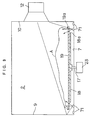
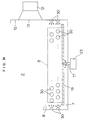
- Fig. 5 is a transverse sectional view of the microwave oven.
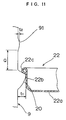
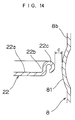
- Fig. 10 is a partially cut-away perspective view of the square tray.
- Fig. 16 is a schematic view illustrating the square tray guided by guide rails provided on opposite side plates.
- Fig. 31 is a front view of a ceiling plate in accordance with a fourteenth embodiment of the present invention.
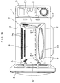
- Fig. 1 is a schematic perspective view of a microwave oven with a door thereof being closed in accordance with a first embodiment of the present invention.
- Fig. 2 is an exploded perspective view of the microwave oven in a state where a square tray is just to be inserted into the microwave oven with the door thereof being open.
- Fig. 3 is a front view of the microwave oven in a state where a food body on a dish is placed on a pan in the microwave oven with the door thereof being open.
- Fig. 4 is a front view of the microwave oven in a state where the pan is removed from the microwave oven with the door thereof being open.
- the microwave oven includes an oven body 1 having a laterally elongated cavity 2, and a door 4 mounted on a front portion 1a of the oven body 1.
- the door 4 is adapted to cover and uncover an opening 3 of the cavity 2 formed in the front portion 1a of the oven body 1.
- An operation panel 11 having various operation keys 11a for setting a desired cooking mode is disposed adjacent to the door 4 on the front portion 1a.
- a square tray 22 (shown in Fig. 2) on which an object to be heated is placed is inserted into the cavity 2 as required.
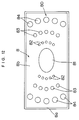
- the rear-face projections 81, 82, 83 and 84 are dispersedly arranged such that neighboring rear-face projections do not contact each other.
- a rear-face projection 81 disposed in the center of the rear plate 8 is configured into a laterally elongated elliptical shape (e.g., major axis: 90 mm, minor axis: 63 mm) which is adapted for the elongated shape of the cavity 2.
- the rear-face projection 81 has a size larger than the other rear-face projections 82, 83 and 84.
- the respective projections 82, 83 and 84 are each formed into a semi-spherical surface.
- the semi-spherical surface of the large-size projection 61 ensures more efficient reflection and distribution of microwaves. Since the large-size projection 61 has a diameter equal to approximately one half the wavelength of the microwaves, the microwave distribution efficiency is further enhanced, thereby ensuring more uniform heating.
- shaomais S Fifteen shaomais S were placed on a pan 19 in an arrangement as shown in Fig. 17. More specifically, four shaomais S were placed in the central portion of the pan 19, and the other eleven shaomais S were placed circularly around these four shaomais S.
- Mug cups filled with milk were placed in the cavities of the microwave ovens each having the ceiling plate formed with only the large-size projection 61, and heated at a power output of 500 W for 130 seconds. Thereafter, a temperature difference ⁇ T between the upper and lower portions of the milk filled in each of the mug cups was measured. The relationship between the distance P and the temperature difference ⁇ T was determined. The result is shown in Fig. 18.
- the temperature difference ⁇ T was very little when the distance P was not greater than one half the wavelength of the microwaves (60 mm). However, the temperature difference ⁇ T steeply increased when the distance P exceeded 60 mm, and then leveled at a constant value when the distance P exceeded 120 mm which was equal to the wavelength. This demonstrates that it is preferable to set the distance P between the boundary line L and the large-size projection 61 having a diameter R of one half the wavelength of the microwaves to not greater than one half the wavelength of the microwaves.
- the temperature difference ⁇ T was substantially the same as the aforesaid constant value.
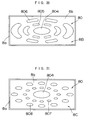
- a rear plate 8B according to a third embodiment as shown in Fig. 20 has rear-face projections 805 and 806 disposed around an elliptical central rear-face projection 804 along contours of ellipses similar in shape to the central projection 804, instead of the rear-face projections 82, 83 and 84 on the rear plate 8 shown in Fig. 12.
- the central projection 804 is formed into a semi-ellipsoidal surface flatter than the central projection 81 on the rear plate 8 shown in Fig. 12.
- the projections 805 and 806 extend along the contours of the ellipses similar in shape to the central projection 804.
- the projections 806 are disposed outside the projections 805.
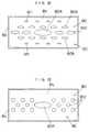
- a rear plate 8C according to a fourth embodiment as shown in Fig. 21 has rear-face projections 807 and 808 disposed around an elliptical central rear-face projection 804 along contours of ellipses similar in shape to the central projection 804. These rear-face projections 807 and 808 are each formed into a semi-ellipsoidal surface, and the projections 808 are larger than the projections 807 and smaller than the central projection 804.
- the use of the rear plate 8C shown in Fig. 21 also presents the aforesaid advantages (1) to (5), like the rear plate 8 shown in Fig. 12.
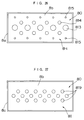
- a rear plate 8F according to a seventh embodiment as shown in Fig. 24 has rear-face projections 813 laterally disposed in a row in a central region with respect to the vertical direction thereof, rear-face projections 814 laterally disposed in rows on the upper and lower sides of the central row of the projections 813, two rear-face projections 815 laterally disposed in a row on the upper side of the upper row of the projections 814 and two rear-face projections 815 laterally disposed in a row on the lower side of the lower row of the projections 814.
- These projections 813, 814 and 815 are each formed into a semi-spherical surface.
- the use of the rear plate 8F shown in Fig. 24 presents the advantages (1) and (3) to (5) among the aforesaid advantages presented by the rear plate 8 shown in Fig. 12.
- a ceiling plate 6C according to a thirteenth embodiment shown in Fig. 30 has a single perforation portion 6a formed in a central region along the lateral axis thereof, two large-size projections 61 respectively formed in regions on the front and rear sides of the perforation portion 6a, and small-size projections 62 dispersedly arranged in the rest of the front and rear regions.
- the formation of these two large-size projections 61 allows uniform heating.
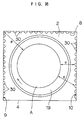
- a left side plate 9, rear plate 8 and right side plate 10 each have a plurality of projections 30 formed thereon in two rows in a region in the vicinity of the upper surface of the pan 19 around a space B to be occupied by an object to be heated.
- the projections 30 each having a semi-spherical surface are dispersedly arranged so as not to contact each other.
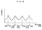
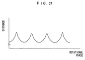
- the distance e between the object A placed on the pan 19 and the door 4, left side plate 9, rear plate 8 or right side plate 10 surrounding the object A changes in accordance with the rotational phase of the pan 19.
- the relationship between the distance e and the rotational phase is shown in Fig. 36. If the interior surface of the cavity has no projection, the distance between the object and the interior surface changes with respect to the rotational phase of the pan as shown in Fig. 37.
- the distance e between the object A and the left side plate 9, rear plate 8 or right side plate 10 is frequently fluctuated due to the projections 30.
- the pan 19 is rotated clockwise as viewed from the top.
Landscapes
- Physics & Mathematics (AREA)
- Electromagnetism (AREA)
- Engineering & Computer Science (AREA)
- Chemical & Material Sciences (AREA)
- Combustion & Propulsion (AREA)
- Mechanical Engineering (AREA)
- General Engineering & Computer Science (AREA)
- Constitution Of High-Frequency Heating (AREA)
- Electric Ovens (AREA)
- Cookers (AREA)
Applications Claiming Priority (3)
| Application Number | Priority Date | Filing Date | Title |
|---|---|---|---|
| JP5305895 | 1995-03-13 | ||
| JP53058/95 | 1995-03-13 | ||
| JP7053058A JP3066283B2 (ja) | 1995-03-13 | 1995-03-13 | 電子レンジ |
Publications (3)
| Publication Number | Publication Date |
|---|---|
| EP0732867A2 true EP0732867A2 (de) | 1996-09-18 |
| EP0732867A3 EP0732867A3 (de) | 1997-01-29 |
| EP0732867B1 EP0732867B1 (de) | 2001-11-14 |
Family
ID=12932258
Family Applications (1)
| Application Number | Title | Priority Date | Filing Date |
|---|---|---|---|
| EP95111452A Expired - Lifetime EP0732867B1 (de) | 1995-03-13 | 1995-07-20 | Mikrowellenherd |
Country Status (9)
| Country | Link |
|---|---|
| US (1) | US5698128A (de) |
| EP (1) | EP0732867B1 (de) |
| JP (1) | JP3066283B2 (de) |
| KR (1) | KR100400140B1 (de) |
| CN (1) | CN1105877C (de) |
| AU (1) | AU703740B2 (de) |
| CA (1) | CA2154329C (de) |
| DE (1) | DE69523891T2 (de) |
| MY (1) | MY137650A (de) |
Cited By (6)
| Publication number | Priority date | Publication date | Assignee | Title |
|---|---|---|---|---|
| EP0848578A3 (de) * | 1996-12-12 | 1998-08-19 | Samsung Electronics Co., Ltd. | Mikrowellenofen |
| EP1345474A3 (de) * | 2002-03-15 | 2007-11-07 | Miele & Cie. KG | Küchengerät mit einem durch Innenwandungen begrenzten Garraum |
| CN100491840C (zh) * | 2003-10-16 | 2009-05-27 | Lg;电子株式会社 | 微波炉以及微波炉内的微波辐射结构 |
| FR2932641A1 (fr) * | 2008-06-17 | 2009-12-18 | Fagorbrandt Sas | Four a micro-ondes a antenne rotative |
| CN103225830A (zh) * | 2007-01-22 | 2013-07-31 | 印刷包装国际公司 | 微波加热构件和用于形成该构件的坯件 |
| GB2528352A (en) * | 2014-05-06 | 2016-01-20 | Mm Microwave Ltd | Heating and/or cooking apparatus |
Families Citing this family (42)
| Publication number | Priority date | Publication date | Assignee | Title |
|---|---|---|---|---|
| US5919391A (en) * | 1998-04-20 | 1999-07-06 | Daewoo Electronics Co., Ltd. | Microwave oven having arcuate concave portions in a cavity for distributing microwaves |
| US6187082B1 (en) | 1999-03-30 | 2001-02-13 | Xerox Corporation | Ink compositions |
| US6045607A (en) * | 1999-03-30 | 2000-04-04 | Xerox Corporation | Ink compositions |
| US6071333A (en) * | 1999-04-27 | 2000-06-06 | Xerox Corporation | Ink compositions |
| US6086661A (en) * | 1999-04-27 | 2000-07-11 | Xerox Corporation | Ink compositions |
| US6110265A (en) * | 1999-04-27 | 2000-08-29 | Xerox Corporation | Ink compositions |
| US6106601A (en) * | 1999-04-27 | 2000-08-22 | Xerox Corporation | Ink compositions |
| US6096125A (en) * | 1999-04-27 | 2000-08-01 | Xerox Corporation | Ink compositions |
| US6066200A (en) * | 1999-04-27 | 2000-05-23 | Xerox Corporation | Ink compositions |
| US6096124A (en) * | 1999-04-27 | 2000-08-01 | Xerox Corporation | Ink compositions |
| US6106599A (en) * | 1999-06-29 | 2000-08-22 | Xerox Corporation | Inks |
| USD440818S1 (en) | 2000-05-16 | 2001-04-24 | Nisshin Industry Co., Ltd. | Projection on a wall of a microwave oven |
| USD440820S1 (en) | 2000-05-16 | 2001-04-24 | Nisshin Industry Co., Ltd. | Projection on a wall of a microwave oven |
| USD440819S1 (en) | 2000-05-16 | 2001-04-24 | Nisshin Industry Co., Ltd. | Projection on a wall of a microwave oven |
| USD447001S1 (en) | 2000-05-16 | 2001-08-28 | Nisshin Industry Co., Ltd. | Projection on a wall of a microwave oven |
| US6432184B1 (en) | 2000-08-24 | 2002-08-13 | Xerox Corporation | Ink compositions |
| US6461417B1 (en) | 2000-08-24 | 2002-10-08 | Xerox Corporation | Ink compositions |
| FR2817948B1 (fr) * | 2000-12-12 | 2003-06-20 | Brandt Cooking | Four a micro-ondes |
| CA2398649C (en) * | 2001-02-05 | 2005-06-21 | Young Hee Lee | Apparatus for uniformly dispersing microwave and heating system using the same |
| DE102004003408A1 (de) | 2004-01-23 | 2005-08-18 | Electrolux Schwanden Ag | Ofenmuffel für einen Garofen mit Mikrowellenbetrieb |
| US10674570B2 (en) | 2006-02-21 | 2020-06-02 | Goji Limited | System and method for applying electromagnetic energy |
| US8839527B2 (en) | 2006-02-21 | 2014-09-23 | Goji Limited | Drying apparatus and methods and accessories for use therewith |
| WO2008102334A1 (en) | 2007-02-21 | 2008-08-28 | Rf Dynamics Ltd. | Rf controlled freezing |
| JP5179382B2 (ja) | 2006-02-21 | 2013-04-10 | ゴジ リミテッド | 電磁加熱 |
| US8653482B2 (en) | 2006-02-21 | 2014-02-18 | Goji Limited | RF controlled freezing |
| IL184672A (en) | 2007-07-17 | 2012-10-31 | Eran Ben-Shmuel | Apparatus and method for concentrating electromagnetic energy on a remotely-located object |
| US9131543B2 (en) | 2007-08-30 | 2015-09-08 | Goji Limited | Dynamic impedance matching in RF resonator cavity |
| JP5152971B2 (ja) * | 2007-12-27 | 2013-02-27 | パナソニック株式会社 | 加熱調理器 |
| KR101569235B1 (ko) | 2008-11-10 | 2015-11-13 | 고지 엘티디. | Rf 에너지를 사용하여 가열하는 장치 및 방법 |
| US9462635B2 (en) | 2009-11-10 | 2016-10-04 | Goji Limited | Device and method for heating using RF energy |
| MX2012012706A (es) | 2010-05-03 | 2013-04-29 | Goji Ltd | Analisis modal. |
| US9295111B2 (en) * | 2012-07-26 | 2016-03-22 | Midea Group Co., Ltd | Microwave oven |
| CN106859386B (zh) * | 2015-12-11 | 2019-11-29 | 佛山市顺德区美的电热电器制造有限公司 | 面包机 |
| RU2646616C2 (ru) * | 2016-03-01 | 2018-03-06 | Самсунг Электроникс Ко., Лтд. | Микроволновая печь |
| US10009957B2 (en) | 2016-03-30 | 2018-06-26 | The Markov Corporation | Electronic oven with infrared evaluative control |
| US10004115B2 (en) | 2016-06-13 | 2018-06-19 | The Markov Corporation | Electronic oven with reflective energy steering |
| JP1599562S (de) * | 2017-09-28 | 2018-03-12 | ||
| CN108513386A (zh) * | 2018-04-27 | 2018-09-07 | 广州市希力动漫科技有限公司 | 一种微波炉 |
| WO2023000783A1 (zh) * | 2021-07-21 | 2023-01-26 | 广东美的厨房电器制造有限公司 | 烹饪器具 |
| CN113507757A (zh) * | 2021-07-21 | 2021-10-15 | 广东美的厨房电器制造有限公司 | 微波烹饪器具 |
| US12529479B2 (en) * | 2021-11-01 | 2026-01-20 | Illinois Tool Works Inc. | Two-level rapid cooking oven and multi-tiered rack assembly for the same |
| CN114294686B (zh) * | 2021-12-22 | 2025-06-03 | 广东美的白色家电技术创新中心有限公司 | 一种微波炉 |
Citations (2)
| Publication number | Priority date | Publication date | Assignee | Title |
|---|---|---|---|---|
| JPS4734553U (de) | 1971-05-15 | 1972-12-18 | ||
| JPS4824206U (de) | 1971-07-30 | 1973-03-20 |
Family Cites Families (7)
| Publication number | Priority date | Publication date | Assignee | Title |
|---|---|---|---|---|
| NL290163A (de) * | 1962-03-14 | |||
| DE1515156A1 (de) * | 1964-07-03 | 1969-07-03 | Siemens Elektrogeraete Gmbh | Garraum eines HF-Strahlungsherdes |
| US3461260A (en) * | 1966-05-16 | 1969-08-12 | Gen Motors Corp | Microwave oven |
| US3946188A (en) * | 1975-06-19 | 1976-03-23 | Raytheon Company | Microwave heating apparatus with browning feature |
| US4683362A (en) * | 1984-09-21 | 1987-07-28 | Yangas Roger A | Reflective apparatus for microwave cooking |
| US4771155A (en) * | 1985-08-14 | 1988-09-13 | Yangas Roger A | Apparatus for promoting the uniform heating of a food product in a radiant energy field |
| FR2663110B1 (fr) * | 1990-06-08 | 1992-08-07 | Thomson Electromenager Sa | Four a mirco-ondes a plateau brasseur d'ondes. |
-
1995
- 1995-03-13 JP JP7053058A patent/JP3066283B2/ja not_active Expired - Fee Related
- 1995-07-17 US US08/503,082 patent/US5698128A/en not_active Expired - Fee Related
- 1995-07-19 MY MYPI95002050A patent/MY137650A/en unknown
- 1995-07-20 DE DE69523891T patent/DE69523891T2/de not_active Expired - Fee Related
- 1995-07-20 CA CA002154329A patent/CA2154329C/en not_active Expired - Fee Related
- 1995-07-20 EP EP95111452A patent/EP0732867B1/de not_active Expired - Lifetime
- 1995-07-24 AU AU27147/95A patent/AU703740B2/en not_active Ceased
- 1995-10-11 CN CN95119009A patent/CN1105877C/zh not_active Expired - Fee Related
-
1996
- 1996-01-15 KR KR1019960000609A patent/KR100400140B1/ko not_active Expired - Fee Related
Patent Citations (2)
| Publication number | Priority date | Publication date | Assignee | Title |
|---|---|---|---|---|
| JPS4734553U (de) | 1971-05-15 | 1972-12-18 | ||
| JPS4824206U (de) | 1971-07-30 | 1973-03-20 |
Cited By (8)
| Publication number | Priority date | Publication date | Assignee | Title |
|---|---|---|---|---|
| EP0848578A3 (de) * | 1996-12-12 | 1998-08-19 | Samsung Electronics Co., Ltd. | Mikrowellenofen |
| EP1345474A3 (de) * | 2002-03-15 | 2007-11-07 | Miele & Cie. KG | Küchengerät mit einem durch Innenwandungen begrenzten Garraum |
| CN100491840C (zh) * | 2003-10-16 | 2009-05-27 | Lg;电子株式会社 | 微波炉以及微波炉内的微波辐射结构 |
| CN103225830A (zh) * | 2007-01-22 | 2013-07-31 | 印刷包装国际公司 | 微波加热构件和用于形成该构件的坯件 |
| CN103225830B (zh) * | 2007-01-22 | 2016-01-20 | 印刷包装国际公司 | 微波加热构件和用于形成该构件的坯件 |
| FR2932641A1 (fr) * | 2008-06-17 | 2009-12-18 | Fagorbrandt Sas | Four a micro-ondes a antenne rotative |
| EP2136605A1 (de) * | 2008-06-17 | 2009-12-23 | FagorBrandt SAS | Mikrowellenherd mit Drehantenne |
| GB2528352A (en) * | 2014-05-06 | 2016-01-20 | Mm Microwave Ltd | Heating and/or cooking apparatus |
Also Published As
| Publication number | Publication date |
|---|---|
| MY137650A (en) | 2009-02-27 |
| US5698128A (en) | 1997-12-16 |
| CN1105877C (zh) | 2003-04-16 |
| JP3066283B2 (ja) | 2000-07-17 |
| DE69523891T2 (de) | 2002-07-04 |
| CA2154329A1 (en) | 1996-09-14 |
| EP0732867A3 (de) | 1997-01-29 |
| AU703740B2 (en) | 1999-04-01 |
| AU2714795A (en) | 1996-09-26 |
| DE69523891D1 (de) | 2001-12-20 |
| JPH08250273A (ja) | 1996-09-27 |
| KR100400140B1 (ko) | 2003-12-24 |
| CA2154329C (en) | 2003-02-04 |
| KR960034871A (ko) | 1996-10-24 |
| EP0732867B1 (de) | 2001-11-14 |
| CN1134532A (zh) | 1996-10-30 |
Similar Documents
| Publication | Publication Date | Title |
|---|---|---|
| US5698128A (en) | Microwave oven with a projection for uniform heating within the cavity | |
| CA2096893C (en) | Wave guide system of a microwave oven | |
| CA1298241C (en) | Microwave container and method of use | |
| EP1458220B1 (de) | Hochfrequenzheizapparat versehen mit Dampferzeugungsfunktion | |
| AU6103396A (en) | Air dispensers for microwave oven | |
| JP4536763B2 (ja) | 蒸気発生機能付き加熱装置 | |
| JP2533896B2 (ja) | マイクロ波調理器具 | |
| JP2010230306A (ja) | 蒸気発生機能付き加熱装置 | |
| JP3059907B2 (ja) | 電子レンジ | |
| JP2001027417A (ja) | 電子レンジ | |
| JP3623676B2 (ja) | 高周波加熱装置 | |
| JP3108313B2 (ja) | 電子レンジ | |
| JP3910115B2 (ja) | 高周波加熱装置 | |
| JP3118388B2 (ja) | 電子レンジ | |
| KR100265634B1 (ko) | 전자렌지의선반조립구조 | |
| JP4035932B2 (ja) | 加熱調理装置 | |
| CA2223752C (en) | Air dispensers for microwave oven | |
| JPH08247470A (ja) | 電子レンジ | |
| JP2012042195A (ja) | 高周波加熱装置 | |
| JP2005009764A (ja) | 電熱装置付高周波加熱装置 | |
| JPS6319794A (ja) | 加熱調理器 | |
| KR19990017331U (ko) | 전자렌지의 고주파 분산구조 | |
| JPH0577930B2 (de) | ||
| KR20050030667A (ko) | 전자 레인지 | |
| KR19990023554U (ko) | 전자렌지용 석쇠 |
Legal Events
| Date | Code | Title | Description |
|---|---|---|---|
| PUAI | Public reference made under article 153(3) epc to a published international application that has entered the european phase |
Free format text: ORIGINAL CODE: 0009012 |
|
| AK | Designated contracting states |
Kind code of ref document: A2 Designated state(s): DE FR GB SE |
|
| PUAL | Search report despatched |
Free format text: ORIGINAL CODE: 0009013 |
|
| AK | Designated contracting states |
Kind code of ref document: A3 Designated state(s): DE FR GB SE |
|
| 17P | Request for examination filed |
Effective date: 19970227 |
|
| 17Q | First examination report despatched |
Effective date: 19990726 |
|
| GRAG | Despatch of communication of intention to grant |
Free format text: ORIGINAL CODE: EPIDOS AGRA |
|
| GRAG | Despatch of communication of intention to grant |
Free format text: ORIGINAL CODE: EPIDOS AGRA |
|
| GRAH | Despatch of communication of intention to grant a patent |
Free format text: ORIGINAL CODE: EPIDOS IGRA |
|
| GRAH | Despatch of communication of intention to grant a patent |
Free format text: ORIGINAL CODE: EPIDOS IGRA |
|
| GRAA | (expected) grant |
Free format text: ORIGINAL CODE: 0009210 |
|
| AK | Designated contracting states |
Kind code of ref document: B1 Designated state(s): DE FR GB SE |
|
| REF | Corresponds to: |
Ref document number: 69523891 Country of ref document: DE Date of ref document: 20011220 |
|
| REG | Reference to a national code |
Ref country code: GB Ref legal event code: IF02 |
|
| ET | Fr: translation filed | ||
| PLBE | No opposition filed within time limit |
Free format text: ORIGINAL CODE: 0009261 |
|
| STAA | Information on the status of an ep patent application or granted ep patent |
Free format text: STATUS: NO OPPOSITION FILED WITHIN TIME LIMIT |
|
| 26N | No opposition filed | ||
| PGFP | Annual fee paid to national office [announced via postgrant information from national office to epo] |
Ref country code: DE Payment date: 20060713 Year of fee payment: 12 |
|
| PGFP | Annual fee paid to national office [announced via postgrant information from national office to epo] |
Ref country code: FR Payment date: 20060719 Year of fee payment: 12 |
|
| EUG | Se: european patent has lapsed | ||
| PG25 | Lapsed in a contracting state [announced via postgrant information from national office to epo] |
Ref country code: SE Free format text: LAPSE BECAUSE OF NON-PAYMENT OF DUE FEES Effective date: 20070721 Ref country code: DE Free format text: LAPSE BECAUSE OF NON-PAYMENT OF DUE FEES Effective date: 20080201 |
|
| REG | Reference to a national code |
Ref country code: FR Ref legal event code: ST Effective date: 20080331 |
|
| PGFP | Annual fee paid to national office [announced via postgrant information from national office to epo] |
Ref country code: SE Payment date: 20060705 Year of fee payment: 12 |
|
| PG25 | Lapsed in a contracting state [announced via postgrant information from national office to epo] |
Ref country code: FR Free format text: LAPSE BECAUSE OF NON-PAYMENT OF DUE FEES Effective date: 20070731 |
|
| PGFP | Annual fee paid to national office [announced via postgrant information from national office to epo] |
Ref country code: GB Payment date: 20080723 Year of fee payment: 14 |
|
| GBPC | Gb: european patent ceased through non-payment of renewal fee |
Effective date: 20090720 |
|
| PG25 | Lapsed in a contracting state [announced via postgrant information from national office to epo] |
Ref country code: GB Free format text: LAPSE BECAUSE OF NON-PAYMENT OF DUE FEES Effective date: 20090720 |