EP0732892B1 - Instrument chirurgical tubulaire - Google Patents
Instrument chirurgical tubulaire Download PDFInfo
- Publication number
- EP0732892B1 EP0732892B1 EP94928869A EP94928869A EP0732892B1 EP 0732892 B1 EP0732892 B1 EP 0732892B1 EP 94928869 A EP94928869 A EP 94928869A EP 94928869 A EP94928869 A EP 94928869A EP 0732892 B1 EP0732892 B1 EP 0732892B1
- Authority
- EP
- European Patent Office
- Prior art keywords
- tube
- spherical
- instrument according
- sleeve
- cylindrical
- Prior art date
- Legal status (The legal status is an assumption and is not a legal conclusion. Google has not performed a legal analysis and makes no representation as to the accuracy of the status listed.)
- Expired - Lifetime
Links
Images
Classifications
-
- A—HUMAN NECESSITIES
- A61—MEDICAL OR VETERINARY SCIENCE; HYGIENE
- A61B—DIAGNOSIS; SURGERY; IDENTIFICATION
- A61B17/00—Surgical instruments, devices or methods
- A61B17/28—Surgical forceps
- A61B17/29—Forceps for use in minimally invasive surgery
-
- A—HUMAN NECESSITIES
- A61—MEDICAL OR VETERINARY SCIENCE; HYGIENE
- A61B—DIAGNOSIS; SURGERY; IDENTIFICATION
- A61B17/00—Surgical instruments, devices or methods
- A61B2017/0046—Surgical instruments, devices or methods with a releasable handle; with handle and operating part separable
-
- A—HUMAN NECESSITIES
- A61—MEDICAL OR VETERINARY SCIENCE; HYGIENE
- A61B—DIAGNOSIS; SURGERY; IDENTIFICATION
- A61B17/00—Surgical instruments, devices or methods
- A61B17/28—Surgical forceps
- A61B17/29—Forceps for use in minimally invasive surgery
- A61B17/2909—Handles
- A61B2017/2912—Handles transmission of forces to actuating rod or piston
- A61B2017/2919—Handles transmission of forces to actuating rod or piston details of linkages or pivot points
- A61B2017/292—Handles transmission of forces to actuating rod or piston details of linkages or pivot points connection of actuating rod to handle, e.g. ball end in recess
-
- A—HUMAN NECESSITIES
- A61—MEDICAL OR VETERINARY SCIENCE; HYGIENE
- A61B—DIAGNOSIS; SURGERY; IDENTIFICATION
- A61B17/00—Surgical instruments, devices or methods
- A61B17/28—Surgical forceps
- A61B17/29—Forceps for use in minimally invasive surgery
- A61B2017/2926—Details of heads or jaws
- A61B2017/2931—Details of heads or jaws with releasable head
Definitions
- the invention relates to a surgical tubular shaft instrument with two hinged together Handle branches, with one held on a handle branch Pipe, a tool stored at its end, a rod-shaped, longitudinally displaceable in the tube Actuator for the tool that over a cylindrical or spherical end articulated with the other handle industry is connected, and with a detachable Connection between tube and actuator on the one hand and the two handle branches on the other, the tube being in a tubular receptacle on one Handle industry insertable and in this by at least a radially movable, in an end position with the tube a positive locking lock body is axially fixable and being on the other Grip branch in a cylindrical end position or spherical end of the actuator partially encompassing restraint is stored, which can be moved to another end position, in which the cylindrical or spherical end in the longitudinal direction is removable from the other handle industry.
- tubular shaft instruments of this type (GB-2 140 735 A), which are used in a wide variety of ways it is important for the purpose of tool replacement and the instrument for cleaning purposes to be able to disassemble as completely as possible.
- Instruments of this type are known in which the Handle branches via threaded connections with the tube and can be connected to the actuator. It takes time to establish and resolve the connection relatively long since fine threads are usually used that need a large number of revolutions. It is also difficult to concentrate Connect parts in this way at the same time, because two different connections must be made.
- Ball locks are a quick connector known per se for surgical instruments (WO 91/05514), however, these are known quick couplings essentially used to be surgical Instruments with brackets or extensions too connect. It is not from the document mentioned known to use a ball ratchet to the shaft a tubular shaft instrument with a grip part connect.
- the sleeve is spring-loaded the end position is moved, in which the displacement path of the locking body most restricted is. This causes the spring to move the sleeve always in the locked position, only against the The force of this spring is a solution to the axial definition of the pipe in the receptacle.
- the tubular receptacle for a stop an outer tube axially displaceably mounted on the tube forms the in the advanced end position detachable storage of the tool on the opposite Locked end of the tube.
- the outer tube can only be moved on the tube when the tube comes out of the tubular receptacle is pulled out, i.e. a replacement of the tool first sets a separation of the entire instrument ahead.
- tubular receptacle about its longitudinal axis is rotatably mounted on the handle branch.
- Rotation of this tubular receptacle can be the tube with the tool attached to it in the desired position be rotated so that the surgeon is completely free in the angular position of the tool.
- the retaining member is designed as a collet is that in the released state under elastic bending the entry or exit of the spherical or enables cylindrical end and this in closed Condition inextricably embraces.
- a collet leaves itself, for example, by inserting it axially into a Lock the sleeve, this insertion can if necessary be made by a threaded nut.
- the Retaining element pivotable on the other handle branch is stored and in the closed state in a spherical or cylindrical end adjoining section of the Actuating element engages, the outer dimensions transverse to the longitudinal direction of the actuating element smaller are than that of the spherical or cylindrical end. It is therefore sufficient to release the rotary connection between the actuating element on the one hand and handle industry on the other, the To pivot the restraining member on the handle branch, i.e. one movement is all it takes to selectively close the door or to reach the release status.
- the retaining member a receiving space for the spherical or cylindrical end with an opening that has a larger, for the Sufficient passage of the spherical or cylindrical end Area and a smaller one for its passage too narrow area, and that the two areas by moving the restraining member either in the longitudinal direction of the actuator before its spherical or cylindrical end are movable.
- the recording room encloses the spherical or cylindrical end and transmits thereby reliable both pulling and pushing movements. Simply by swiveling the restraining element, it becomes possible to release the actuator, then namely if the larger area of the opening in the longitudinal direction of the Actuator is directed.
- the actuator in its end positions can be positioned by means of elastic catches.
- the opening of the receiving space can be keyhole-shaped in particular be.
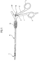
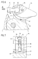
- the tubular shaft instrument shown in the drawing includes two handle branches pivotally connected to each other 1 and 2, each with a finger opening 3 and 4. Die two handle branches 1 and 2 are by a screw connection 5 pivotally connected. At a Handle branch 1 is held a shaft 6, on the free At the end there is a tool 7, for example the Can be in the form of scissors or pliers. Internally the shaft 6 is a rod-shaped actuating element 8 arranged longitudinally displaceable, on the one hand with the Tool 7 and on the other hand with the other handle branch 2 is articulated so that when opening and closing the handle branches 1 and 2 by a pull or push movement of the actuating element 8, the tool 7 is opened and can be closed.
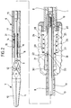
- This tool 7 includes in the illustrated embodiment 2 on a bracket 9 rotatably mounted parts 10, 11, the transmission means 12 with the actuator 8 are pivotally connected (Fig. 2).
- This bracket 9 is detachably connected to a tube 13.
- the holder 9 carries a tube which is immersed in the tube 13 Extension 14 with a circumferential groove 15.
- Das Tube 13 is in at its free end through longitudinal slots elastically bendable tongues 16 divided on their free end are bent inwards. These tongues 16 surround the extension 14 and dive with the bent End in the circumferential groove 15 so that the extension 14 is fixed in the tube 6 in the axial direction.
- the tube 13 and the outer tube slidably mounted thereon 17 together form the shaft 6, which is detachable with the Handle branch 1 can be connected.
- the outer diameter of the Tube 13 corresponds to the inner diameter of the receptacle 18.
- the tube 13 has at its in the receptacle 18th inserted end of the longitudinal slots 19 into which an in of the tubular receptacle 18 held projection 20 protrudes.
- the tube 13 is in the receptacle 18th non-rotatably mounted.
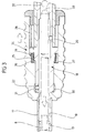
- a locking body 22 mounted in the form of a ball In a radial bore 21 of the tubular receptacle 18 a locking body 22 mounted in the form of a ball, the tube 13 inserted into the receptacle 18 into a Recess 23 immersed in the outer jacket of the tube 13.
- Radial bore 21 on the inside is not completely continuous executed so that the ball 22nd even when the tube 13 is missing do not fall radially inwards out of the radial bore 21 can.
- the radial bore 21 formed continuously so that the ball 22 radially after is freely movable outside.
- a sleeve 24 surrounding the receptacle 18 is mounted, the one in between the receptacle 18 and the Sleeve 24 arranged annular space 25 a coil spring 26th surrounds.
- This is based on the one hand on a stage 27 of the Sleeve 24 and on the other hand at a step 28 of the receptacle 18 and thus acts on the sleeve 24 with a this in the direction of the tool 7 shifting force.
- the step 28 is in a longitudinal groove 29 of the sleeve 24 performed, so that the sleeve 24 against rotation is secured relative to the receptacle 18.
- the movement of the sleeve 24 in the direction of the tool 7 is limited in that the sleeve 24 on the outer tube 17 strikes and thus this in its foremost Moves position in which the tongues 16 are locked (Fig. 2). Only against the action of the coil spring 26 the sleeve 24 pushed back can therefore the outer tube 17th are pushed back so far that the bracket 9 from the Tube 13 can be pulled out.
- the outer tube 17 strikes the receptacle 18, also in this case it would be necessary to move the outer tube 17, pull the tube 6 out of the receptacle 18. In in this case, the movement of the sleeve 24 by a other suitable stop can be limited.
- the sleeve 24 lies with its inner wall on the outside the receptacle 18 in such a way that the radial bore 21 is closed is so that when the coil spring 26 prevents the movement of the ball 22 radially outward becomes.
- the dimensions are such that in in this case, the ball 22 is immersed in the recess 23.
- the rod-shaped actuating element 8 projects through a central bore 31 of the extension 14 and stands to the rear over the tube 13, so far that it also stands out from the handle branch 1. In this Area enters the rod-shaped actuating element 8 spherical end 32, which via a connecting section 33 with a smaller outer diameter with the actuator 8 is connected.
- the spherical end 32 forms an articulated connection with the second handle branch 2.
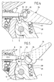
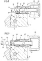
- FIGS. 4 and 5 first embodiment on the handle branch 2 um one transverse to the longitudinal direction of the actuating element 8 extending horizontal axis a pivot lever 34 pivotable stored, the blind hole open on one side 35 has. This is parallel to one their longitudinal direction extending longitudinal slot 36 with the Environment in connection.
- the diameter of the blind hole 35 corresponds essentially to the outer diameter of the spherical end 32, the width of the longitudinal slot 36 is chosen smaller and corresponds essentially to that Diameter of the actuating element 8 in the narrower connecting section 33.
- the pivot lever 34 is between a closed position (Fig. 4) and an open position (Fig. 5) pivotable and is in both end positions by a spring engaging in recesses 37 and 38 respectively Ball 39 set.
- this Blind hole 35 thus forms a receiving space for the spherical end 32.
- the blind hole 35 is open upwards, ie vertically to the longitudinal direction of the actuating element 8, so that pulling the actuator out to the front of the instrument is impossible.
- the pivot lever 34 is in the End positions in this case not by a spring-loaded Ball set but with a retaining pin 40, the resilient in notches 41, 42 of the pivot lever 34 clicks into place.
- the elasticity of the for the pivot lever material used here can be sufficient to to enable necessary shifts.
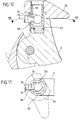
- This collet 44 is on the Handle branch 2 a collet 44 about a transverse to the longitudinal axis of the actuator 8 arranged horizontal Axis 45 pivotally mounted.
- This collet 44 includes a bearing sleeve 43 and one axially immovable and rotatable in this internal threaded sleeve 47 with a Handle part 46.
- In the inner threaded sleeve 47 is a piece of pipe 48 screwed into an external thread 49, which when turning the handle part 46 more or less deep is drawn into the bearing sleeve 43.
- a swivel body 54 used, which around the vertical axis of the Bore 53 is rotatable.
- a blind hole 55 is arranged for bore 53, the via a transverse keyhole-shaped opening 56 communicates with the outside space.
- a first Position is the narrow area of the keyhole-shaped Opening 56 in the longitudinal direction of the actuating element 8 arranged so that an exit of the larger spherical End 32 is prevented from being in the other end position however, the greater part of the keyhole shaped Opening 56 in this direction so that in this Position the spherical end 32 out of the opening 56 can.
- the outer tube 17 can be moved so that it the tongues 16 covered. This unit is then in the tubular receptacle 18 inserted, at the same time the sleeve 24 against the action of the coil spring 26 is moved. This is an unimpeded one Entry of the tube 13 into the receptacle 18 possible without that the ball 22 prevents this entry movement.
- the projection 20 enters one the longitudinal slots 19 and thereby aligns the tube in Circumferential direction in the desired angular position.
- the Sleeve 24 released so that it is under the action the coil spring 26 moves to the closed position and thereby the ball 22 into the aligned recess 23 of the tube 13 inserts.
- the tube 13 is in the Recording determined in the axial direction. This gives a fixation of the outer tube 17 on the Tube 13, so that now the tool 7 in the tube 6th is permanently locked.
- the spherical end 32 of the actuating element 8 is at this insertion movement of the tube 13 in the open position standing restraint occurred.
- the restraining member in the closed position becomes spherical End 32 partially surrounded by the retaining member articulated and also prevents the end 32 in Direction of the actuator 8 are moved can. This allows tensile and compressive forces from the Handle industry 2 transferred to the actuator 8.
Landscapes
- Health & Medical Sciences (AREA)
- Surgery (AREA)
- Life Sciences & Earth Sciences (AREA)
- Medical Informatics (AREA)
- Nuclear Medicine, Radiotherapy & Molecular Imaging (AREA)
- Engineering & Computer Science (AREA)
- Biomedical Technology (AREA)
- Heart & Thoracic Surgery (AREA)
- Ophthalmology & Optometry (AREA)
- Molecular Biology (AREA)
- Animal Behavior & Ethology (AREA)
- General Health & Medical Sciences (AREA)
- Public Health (AREA)
- Veterinary Medicine (AREA)
- Surgical Instruments (AREA)
- Quick-Acting Or Multi-Walled Pipe Joints (AREA)
Claims (11)
- Instrument chirurgical à fût tubulaire comportant deux branches de prise (1, 2), reliées l'une à l'autre avec articulation, un tube (13) maintenu sur une branche de prise (1), un outil (7) porté, de façon détachable, à l'extrémité du tube, un élément de manoeuvre (8) en forme de tige, porté dans le tube (13) avec liberté de coulissement, pour l'outil (7), élément qui, par l'intermédiaire d'une extrémité cylindrique ou sphérique (32), est relié à l'autre branche de prise (2) avec articulation, et comportant une liaison détachable entre tube (13) et élément de manoeuvre (8) d'une part et les deux branches de prise (1, 2) d'autre part, dans lequel le tube (13) peut coulisser dans un réceptacle tubulaire (18) prévu sur la première branche de prise (1) et se bloquer axialement dans cette branche au moyen d'au moins un élément de verrouillage (22) qui peut se déplacer radialement et qui, dans une position d'extrémité, participe avec le tube (13) à une fixation par complémentarité de forme, et dans lequel, sur l'autre branche de prise (2), est porté un organe de retenue (34, 44, 54) qui, dans une position d'extrémité, enserre partiellement l'extrémité cylindrique ou sphérique (32) de l'élément de manoeuvre (8) et que l'on peut amener dans une autre position d'extrémité dans laquelle on peut, selon la direction longitudinale, séparer l'extrémité cylindrique ou sphérique (32) d'avec l'autre branche de prise (2),
caractérisé par le fait que l'élément de verrouillage (22) est une bille, que le déplacement radial de l'élément de verrouillage (22) est limité par une butée qui s'appuie contre la face extérieure de l'élément de verrouillage (22) et qui est formée par un manchon (24) qui peut coulisser axialement sur le réceptacle tubulaire (18), que le manchon (24) peut coulisser par rapport à l'élément de verrouillage (22) de façon que l'élément de verrouillage (22) puisse coulisser radialement plus loin vers l'extérieur, que le manchon (24) forme une butée pour un tube extérieur (17) qui peut coulisser axialement sur le tube (13) et qui, dans la position d'extrémité où il a coulissé vers l'avant, verrouille la portée amovible de l'outil (7) à l'extrémité opposée du tube (13), et que le manchon (24) peut coulisser en direction des branches de prise (1, 2) pour déverrouiller le verrouillage du tube (13). - Instrument selon la revendication 1,
caractérisé par le fait que, contraint par un ressort, le manchon (24) coulisse dans la position d'extrémité dans laquelle la course de coulissement de l'élément de verrouillage (22) est la plus limitée. - Instrument selon l'une des revendications 1 ou 2,
caractérisé par le fait que le réceptacle tubulaire (18) forme une butée pour un tube extérieur (17) qui est porté, avec liberté de coulissement axial, sur le tube (13) et qui, dans la position d'extrémité où il a coulissé vers l'avant, verrouille la portée amovible de l'outil (7) à l'extrémité opposée du tube (13). - Instrument selon l'une des revendications 1 ou 2,
caractérisé par le fait que le tube (13), lors de son coulissement dans le réceptacle tubulaire (18), est garanti à l'égard d'une rotation autour de l'axe longitudinal du tube (13) par venue en prise de saillies et d'évidements (19, 20). - Instrument selon la revendication 4,
caractérisé par le fait que des saillies et des évidements (19, 20) peuvent venir en prise dans des positions angulaires différentes. - Instrument selon l'une des revendications précédentes,
caractérisé par le fait que le réceptacle tubulaire (18) est porté sur la branche de prise (1) avec liberté de rotation autour de son propre axe longitudinal. - Instrument selon l'une des revendications précédentes,
caractérisé par le fait que l'organe de retenue est conçu sous forme de mors de serrage (44) qui, à l'état ouvert, permet, sous réserve d'un cintrage élastique, l'entrée ou la sortie de l'extrémité sphérique ou cylindrique (32) et, à l'état fermé, enserre celle-ci de façon imperdable. - Instrument selon l'une des revendications 1 à 6,
caractérisé par le fait que l'organe de retenue (34, 54) est porté sur l'autre branche de prise (2) avec liberté de pivotement et, à l'état fermé, vient en prise sur un tronçon (33) de l'élément de manoeuvre (8) qui se raccorde à l'extrémité sphérique ou cylindrique (32) et dont les dimensions extérieures, perpendiculairement à la direction longitudinale de l'élément de manoeuvre (8), sont inférieures à celles de l'extrémité sphérique ou cylindrique (32). - Instrument selon la revendication 8,
caractérisé par le fait que l'organe de retenue (34, 54) présente, pour l'extrémité sphérique ou cylindrique (32), un espace de réception (35, 55) avec une ouverture (35, 36; 56) qui comporte une zone plus grande, suffisante pour le passage de l'extrémité sphérique ou cylindrique (32), et une zone plus petite, trop étroite pour son passage, et que, par le mouvement de l'organe de retenue (34, 54), les deux zones peuvent être amenées au choix, selon la direction longitudinale de l'élément de manoeuvre (8), devant son extrémité sphérique ou devant son extrémité cylindrique (32). - Instrument selon la revendication 9,
caractérisé par le fait que l'organe de retenue (34, 54) peut être positionné dans ses positions d'extrémité par des crantages élastiques (39, 40). - Instrument selon l'une des revendications 9 ou 10,
caractérisé par le fait que l'ouverture (56) a la forme d'un trou de serrure.
Applications Claiming Priority (3)
| Application Number | Priority Date | Filing Date | Title |
|---|---|---|---|
| DE4341736 | 1993-12-08 | ||
| DE4341736A DE4341736A1 (de) | 1993-12-08 | 1993-12-08 | Chirurgisches Rohrschaftinstrument |
| PCT/EP1994/003308 WO1995015720A1 (fr) | 1993-12-08 | 1994-10-06 | Instrument chirurgical tubulaire |
Publications (2)
| Publication Number | Publication Date |
|---|---|
| EP0732892A1 EP0732892A1 (fr) | 1996-09-25 |
| EP0732892B1 true EP0732892B1 (fr) | 1998-09-09 |
Family
ID=6504411
Family Applications (1)
| Application Number | Title | Priority Date | Filing Date |
|---|---|---|---|
| EP94928869A Expired - Lifetime EP0732892B1 (fr) | 1993-12-08 | 1994-10-06 | Instrument chirurgical tubulaire |
Country Status (5)
| Country | Link |
|---|---|
| US (1) | US5630832A (fr) |
| EP (1) | EP0732892B1 (fr) |
| DE (2) | DE4341736A1 (fr) |
| ES (1) | ES2122335T3 (fr) |
| WO (1) | WO1995015720A1 (fr) |
Families Citing this family (29)
| Publication number | Priority date | Publication date | Assignee | Title |
|---|---|---|---|---|
| US5810864A (en) * | 1995-09-03 | 1998-09-22 | Schaller; Guenter | Surgical instrument system |
| US5964717A (en) * | 1997-01-06 | 1999-10-12 | Symbiosis Corporation | Biopsy forceps having detachable handle and distal jaws |
| US6309403B1 (en) | 1998-06-01 | 2001-10-30 | Board Of Trustees Operating Michigan State University | Dexterous articulated linkage for surgical applications |
| DE19833600A1 (de) * | 1998-07-25 | 2000-03-02 | Storz Karl Gmbh & Co Kg | Medizinische Zange mit zwei unabhängig voneinander beweglichen Maulteilen |
| US6270508B1 (en) * | 1998-10-26 | 2001-08-07 | Charles H. Klieman | End effector and instrument for endoscopic and general surgery needle control |
| DE19930426C2 (de) | 1999-07-01 | 2001-05-03 | Storz Karl Gmbh & Co Kg | Medizinisches, insbesondere chirurgisches Instrument |
| ES2179735B2 (es) * | 2000-06-16 | 2004-10-16 | Alejandro Baguena Oliete | Instrumento de corte para cirugia artroscopica. |
| US6638280B2 (en) * | 2001-10-10 | 2003-10-28 | Codman & Shurtleff, Inc. | Rongeur with drainage |
| US6991633B2 (en) * | 2001-10-10 | 2006-01-31 | Codman & Shurtleff, Inc. | Rongeur with detachable crossbar |
| US6685710B2 (en) | 2001-10-10 | 2004-02-03 | Codman & Shurtleff, Inc. | Rongeur with detachable crossbar |
| DE10156313A1 (de) * | 2001-11-19 | 2003-06-05 | Wolf Gmbh Richard | Medizinische Zange |
| US7410494B2 (en) * | 2003-06-20 | 2008-08-12 | International And Surgical Innovations, Llc | Device for grasping and/or severing |
| DE10339646A1 (de) * | 2003-08-28 | 2005-03-24 | Robert Bosch Gmbh | Fahrerinformationseinrichtung |
| DE10357105B3 (de) | 2003-12-06 | 2005-04-07 | Richard Wolf Gmbh | Medizinisches Instrument |
| US7703653B2 (en) | 2007-09-28 | 2010-04-27 | Tyco Healthcare Group Lp | Articulation mechanism for surgical instrument |
| US8398673B2 (en) * | 2008-02-15 | 2013-03-19 | Surgical Innovations V.O.F. | Surgical instrument for grasping and cutting tissue |
| DE102008017298A1 (de) * | 2008-03-31 | 2009-10-01 | Karl Storz Gmbh & Co. Kg | Medizinisches Instrument mit flexiblem Einsatz |
| GB2466180B (en) * | 2008-12-05 | 2013-07-10 | Surgical Innovations Ltd | Surgical instrument, handle for a surgical instrument and surgical instrument system |
| US8844942B1 (en) | 2010-06-25 | 2014-09-30 | Greatbatch Ltd. | Quick-load connector for a surgical tool |
| CN103648414A (zh) * | 2011-07-11 | 2014-03-19 | 意昂外科手术有限公司 | 腹腔镜抓钳 |
| DE102011056684A1 (de) * | 2011-12-20 | 2013-06-20 | Stefan Koscher | Chirurgisches Instrument |
| DE102012016396B4 (de) * | 2012-08-21 | 2015-04-02 | Olympus Winter & Ibe Gmbh | Chirurgische Zange |
| KR101753504B1 (ko) * | 2013-02-07 | 2017-07-03 | 텔리플렉스 메디컬 인코포레이티드 | 엔드 이펙터 연결 및 작동 시스템 |
| US10376673B2 (en) | 2015-06-19 | 2019-08-13 | Evalve, Inc. | Catheter guiding system and methods |
| US10238494B2 (en) | 2015-06-29 | 2019-03-26 | Evalve, Inc. | Self-aligning radiopaque ring |
| US10413408B2 (en) | 2015-08-06 | 2019-09-17 | Evalve, Inc. | Delivery catheter systems, methods, and devices |
| US10238495B2 (en) | 2015-10-09 | 2019-03-26 | Evalve, Inc. | Delivery catheter handle and methods of use |
| USD809139S1 (en) | 2015-10-09 | 2018-01-30 | Evalve, Inc. | Handle for a medical device |
| US10932781B2 (en) | 2018-02-06 | 2021-03-02 | Ethicon Llc | Features to align and close linear surgical stapler |
Family Cites Families (9)
| Publication number | Priority date | Publication date | Assignee | Title |
|---|---|---|---|---|
| DE8316034U1 (de) * | 1983-06-01 | 1983-09-29 | Richard Wolf Gmbh, 7134 Knittlingen | Scherengriff für austauschbare Zangeneinsätze |
| US4944741A (en) * | 1988-12-09 | 1990-07-31 | Hasson Harrith M | Laproscopic instrument with pivotable support arm |
| JPH069622Y2 (ja) * | 1989-08-11 | 1994-03-16 | オリンパス光学工業株式会社 | 鉗子装置の操作部 |
| DE3934610A1 (de) * | 1989-10-17 | 1991-04-25 | Aesculap Ag | Schnellkupplung fuer chirurgische instrumente |
| DE9007356U1 (de) * | 1990-05-18 | 1991-05-16 | Olympus Winter & Ibe Gmbh, 22045 Hamburg | Medizinisch endoskopisches Greif- bzw. Schneidwerkzeug |
| EP0513471A3 (en) * | 1991-04-19 | 1993-02-03 | Lutz Kothe | Surgical instrument |
| DE9202132U1 (de) * | 1992-02-19 | 1992-04-23 | Aesculap AG, 7200 Tuttlingen | Chirurgisches Instrument |
| US5368606A (en) * | 1992-07-02 | 1994-11-29 | Marlow Surgical Technologies, Inc. | Endoscopic instrument system |
| US5350391A (en) * | 1992-10-19 | 1994-09-27 | Benedetto Iacovelli | Laparoscopic instruments |
-
1993
- 1993-12-08 DE DE4341736A patent/DE4341736A1/de not_active Withdrawn
-
1994
- 1994-10-06 US US08/656,252 patent/US5630832A/en not_active Expired - Lifetime
- 1994-10-06 EP EP94928869A patent/EP0732892B1/fr not_active Expired - Lifetime
- 1994-10-06 WO PCT/EP1994/003308 patent/WO1995015720A1/fr not_active Ceased
- 1994-10-06 DE DE59406896T patent/DE59406896D1/de not_active Expired - Fee Related
- 1994-10-06 ES ES94928869T patent/ES2122335T3/es not_active Expired - Lifetime
Also Published As
| Publication number | Publication date |
|---|---|
| ES2122335T3 (es) | 1998-12-16 |
| WO1995015720A1 (fr) | 1995-06-15 |
| DE4341736A1 (de) | 1995-06-14 |
| EP0732892A1 (fr) | 1996-09-25 |
| US5630832A (en) | 1997-05-20 |
| DE59406896D1 (de) | 1998-10-15 |
Similar Documents
| Publication | Publication Date | Title |
|---|---|---|
| WO1995015720A1 (fr) | Instrument chirurgical tubulaire | |
| DE19650204C2 (de) | Chirurgische Stanze | |
| DE3728149C2 (fr) | ||
| DE19707373C1 (de) | Bajonettkupplung zum lösbaren Verbinden zweier Rohrschaftinstrumente oder -instrumententeile | |
| EP1196097B1 (fr) | Instrument chirurgical a element tubulaire | |
| DE4440035C2 (de) | Instrument zum Morcellieren | |
| DE10041984B4 (de) | Vorrichtung zur Verriegelung der Lenkspindel eines Fahrzeuges | |
| DE29819914U1 (de) | Endoskopisches Einsetzinstrumentarium | |
| DE19930426C2 (de) | Medizinisches, insbesondere chirurgisches Instrument | |
| EP0671149A1 (fr) | Dispositif de pose d'un anneau d'anastomose | |
| EP2090384A2 (fr) | Dispositif d'élargissement de tuyaux | |
| EP3380026B1 (fr) | Instrument de manipulation pour une vis de fixation osseuse | |
| WO1991006252A1 (fr) | Vis a os | |
| EP2090385A2 (fr) | Dispositif d'élargissement de tuyaux | |
| DE102017010033A1 (de) | Medizinische Vorrichtung | |
| EP2261447A2 (fr) | Cadenas | |
| EP0732893B1 (fr) | Instrument chirurgical tubulaire | |
| WO1995015722A1 (fr) | Instrument a utilisation chirurgicale | |
| EP1883078B1 (fr) | Dispositif destiné à la manipulation de petits composants | |
| EP4054447B1 (fr) | Instrument médical à tige coulissante | |
| EP3392419A1 (fr) | Système de fixation | |
| DE9407621U1 (de) | Medizinisches Instrument | |
| EP4384126B1 (fr) | Dispositif d'extension permanente du pénis | |
| DE9318814U1 (de) | Chirurgisches Rohrschaftinstrument | |
| WO1999044517A1 (fr) | Instrument chirurgical a corps tubulaire |
Legal Events
| Date | Code | Title | Description |
|---|---|---|---|
| PUAI | Public reference made under article 153(3) epc to a published international application that has entered the european phase |
Free format text: ORIGINAL CODE: 0009012 |
|
| 17P | Request for examination filed |
Effective date: 19960423 |
|
| AK | Designated contracting states |
Kind code of ref document: A1 Designated state(s): DE ES FR GB IT |
|
| GRAG | Despatch of communication of intention to grant |
Free format text: ORIGINAL CODE: EPIDOS AGRA |
|
| 17Q | First examination report despatched |
Effective date: 19971218 |
|
| GRAG | Despatch of communication of intention to grant |
Free format text: ORIGINAL CODE: EPIDOS AGRA |
|
| GRAH | Despatch of communication of intention to grant a patent |
Free format text: ORIGINAL CODE: EPIDOS IGRA |
|
| GRAH | Despatch of communication of intention to grant a patent |
Free format text: ORIGINAL CODE: EPIDOS IGRA |
|
| GRAA | (expected) grant |
Free format text: ORIGINAL CODE: 0009210 |
|
| ITF | It: translation for a ep patent filed | ||
| AK | Designated contracting states |
Kind code of ref document: B1 Designated state(s): DE ES FR GB IT |
|
| REF | Corresponds to: |
Ref document number: 59406896 Country of ref document: DE Date of ref document: 19981015 |
|
| GBT | Gb: translation of ep patent filed (gb section 77(6)(a)/1977) |
Effective date: 19981012 |
|
| REG | Reference to a national code |
Ref country code: ES Ref legal event code: FG2A Ref document number: 2122335 Country of ref document: ES Kind code of ref document: T3 |
|
| ET | Fr: translation filed | ||
| RAP2 | Party data changed (patent owner data changed or rights of a patent transferred) |
Owner name: AESCULAP AG & CO. KG |
|
| PLBE | No opposition filed within time limit |
Free format text: ORIGINAL CODE: 0009261 |
|
| STAA | Information on the status of an ep patent application or granted ep patent |
Free format text: STATUS: NO OPPOSITION FILED WITHIN TIME LIMIT |
|
| 26N | No opposition filed | ||
| REG | Reference to a national code |
Ref country code: FR Ref legal event code: CJ Ref country code: FR Ref legal event code: CD |
|
| REG | Reference to a national code |
Ref country code: GB Ref legal event code: IF02 |
|
| PGFP | Annual fee paid to national office [announced via postgrant information from national office to epo] |
Ref country code: ES Payment date: 20080911 Year of fee payment: 15 |
|
| PGFP | Annual fee paid to national office [announced via postgrant information from national office to epo] |
Ref country code: IT Payment date: 20080902 Year of fee payment: 15 Ref country code: FR Payment date: 20080717 Year of fee payment: 15 |
|
| PGFP | Annual fee paid to national office [announced via postgrant information from national office to epo] |
Ref country code: DE Payment date: 20081002 Year of fee payment: 15 |
|
| PGFP | Annual fee paid to national office [announced via postgrant information from national office to epo] |
Ref country code: GB Payment date: 20081001 Year of fee payment: 15 |
|
| REG | Reference to a national code |
Ref country code: FR Ref legal event code: ST Effective date: 20100630 |
|
| PG25 | Lapsed in a contracting state [announced via postgrant information from national office to epo] |
Ref country code: FR Free format text: LAPSE BECAUSE OF NON-PAYMENT OF DUE FEES Effective date: 20091102 Ref country code: DE Free format text: LAPSE BECAUSE OF NON-PAYMENT OF DUE FEES Effective date: 20100501 |
|
| PG25 | Lapsed in a contracting state [announced via postgrant information from national office to epo] |
Ref country code: GB Free format text: LAPSE BECAUSE OF NON-PAYMENT OF DUE FEES Effective date: 20091006 |
|
| REG | Reference to a national code |
Ref country code: ES Ref legal event code: FD2A Effective date: 20110303 |
|
| PG25 | Lapsed in a contracting state [announced via postgrant information from national office to epo] |
Ref country code: IT Free format text: LAPSE BECAUSE OF NON-PAYMENT OF DUE FEES Effective date: 20091006 |
|
| PG25 | Lapsed in a contracting state [announced via postgrant information from national office to epo] |
Ref country code: ES Free format text: LAPSE BECAUSE OF NON-PAYMENT OF DUE FEES Effective date: 20110301 |
|
| PG25 | Lapsed in a contracting state [announced via postgrant information from national office to epo] |
Ref country code: ES Free format text: LAPSE BECAUSE OF NON-PAYMENT OF DUE FEES Effective date: 20091007 |