EP2261447A2 - Cadenas - Google Patents
Cadenas Download PDFInfo
- Publication number
- EP2261447A2 EP2261447A2 EP20100005359 EP10005359A EP2261447A2 EP 2261447 A2 EP2261447 A2 EP 2261447A2 EP 20100005359 EP20100005359 EP 20100005359 EP 10005359 A EP10005359 A EP 10005359A EP 2261447 A2 EP2261447 A2 EP 2261447A2
- Authority
- EP
- European Patent Office
- Prior art keywords
- cylinder core
- lock cylinder
- opening
- padlock
- lock
- Prior art date
- Legal status (The legal status is an assumption and is not a legal conclusion. Google has not performed a legal analysis and makes no representation as to the accuracy of the status listed.)
- Granted
Links
Images




Classifications
-
- E—FIXED CONSTRUCTIONS
- E05—LOCKS; KEYS; WINDOW OR DOOR FITTINGS; SAFES
- E05B—LOCKS; ACCESSORIES THEREFOR; HANDCUFFS
- E05B67/00—Padlocks; Details thereof
- E05B67/06—Shackles; Arrangement of the shackle
- E05B67/22—Padlocks with sliding shackles, with or without rotary or pivotal movement
-
- E—FIXED CONSTRUCTIONS
- E05—LOCKS; KEYS; WINDOW OR DOOR FITTINGS; SAFES
- E05B—LOCKS; ACCESSORIES THEREFOR; HANDCUFFS
- E05B67/00—Padlocks; Details thereof
-
- E—FIXED CONSTRUCTIONS
- E05—LOCKS; KEYS; WINDOW OR DOOR FITTINGS; SAFES
- E05B—LOCKS; ACCESSORIES THEREFOR; HANDCUFFS
- E05B67/00—Padlocks; Details thereof
- E05B67/06—Shackles; Arrangement of the shackle
- E05B67/22—Padlocks with sliding shackles, with or without rotary or pivotal movement
- E05B67/24—Padlocks with sliding shackles, with or without rotary or pivotal movement with built- in cylinder locks
-
- Y—GENERAL TAGGING OF NEW TECHNOLOGICAL DEVELOPMENTS; GENERAL TAGGING OF CROSS-SECTIONAL TECHNOLOGIES SPANNING OVER SEVERAL SECTIONS OF THE IPC; TECHNICAL SUBJECTS COVERED BY FORMER USPC CROSS-REFERENCE ART COLLECTIONS [XRACs] AND DIGESTS
- Y10—TECHNICAL SUBJECTS COVERED BY FORMER USPC
- Y10T—TECHNICAL SUBJECTS COVERED BY FORMER US CLASSIFICATION
- Y10T70/00—Locks
- Y10T70/40—Portable
- Y10T70/413—Padlocks
- Y10T70/437—Key-controlled
- Y10T70/446—Rigid shackle
- Y10T70/452—Sliding
-
- Y—GENERAL TAGGING OF NEW TECHNOLOGICAL DEVELOPMENTS; GENERAL TAGGING OF CROSS-SECTIONAL TECHNOLOGIES SPANNING OVER SEVERAL SECTIONS OF THE IPC; TECHNICAL SUBJECTS COVERED BY FORMER USPC CROSS-REFERENCE ART COLLECTIONS [XRACs] AND DIGESTS
- Y10—TECHNICAL SUBJECTS COVERED BY FORMER USPC
- Y10T—TECHNICAL SUBJECTS COVERED BY FORMER US CLASSIFICATION
- Y10T70/00—Locks
- Y10T70/80—Parts, attachments, accessories and adjuncts
- Y10T70/8432—For key-operated mechanism
Definitions
- a padlock according to US 5,377,511 is characterized by the fact that the bracket can be removed in a simple manner completely from the lock body and replaced with another bracket when needed. In such a padlock, it is thus possible to subsequently change the length of the bracket, its shape and / or its material by such an exchange.
- the slide constructed in this case as a ball valve has an additional recess (position 33 in FIG US 5,377,511 ) whose depth is greater than the depth of its other two recesses (positions 26 in FIG US 5,377,511 ). While these two other recesses allow only a movement of the here designed as a closing ball locking element in such a position in which the padlock although open, but the bracket can not be completely removed from the lock body, allows the intervention of a closing ball in the additional when the padlock is open , deeper recess that the bracket can be moved out of the lock body and replaced with another bracket.
- a disadvantage of a padlock according to US 5,377,511 is the fact that it may occur in an expansion of the lock cylinder, that the ball valve and possibly also the spring biasing the ball valve in its locking position, accidentally fall out of the lock body, so that it is difficult for the non-specially trained user of the padlock to re-assemble these parts correctly.
- the onset of said spring prepares problems.
- a further disadvantage is that only lock cylinder can be used with stop function, so that an exchange of lock cylinders is limited.
- padlocks with an automatic function also allow the key to be turned into its triggering position and the key to be removed from the lock cylinder when the padlock is open, ie when the legs of the bracket are not locked in the lock body.
- a removal of the key from the lock cylinder so on the one hand is possible if the padlock - as mentioned - is open and on the other hand, even if the padlock is locked.
- Automatic padlocks are also characterized by the fact that they can be locked without the key in the lock cylinder by simply pushing the handle into the lock body. Due to the initially mentioned bias of the slider or ball valve, this is moved to such a bow movement in its locking position, so that the moved into the lock body strap with its two legs is also locked therein.
- the coupling piece can be removed from the padlock after the lock cylinder bolted to the lock body has been released from this and moved out of the lock body.
- the coupling piece After removal of the lock cylinder, the coupling piece is usually still in the range of the engagement element of the ball valve, and it often happens that the coupling piece on the front side of the ball valve due to adhesion forces, which are reinforced, for example by the presence of lubricants, adheres, so that the coupling piece can not solve the ball valve only due to its gravity.
- the curtain lock according to the invention is also intended to enable the use of lock cylinders without the one stop function, in accordance with the padlock described above in connection with the ironing exchange US 5,377,511 was explained.
- this object is achieved in that between slide and lock cylinder core a lock body mounted in the lock plate is provided, which has an opening through which protrudes when mounted padlock, the driver of the lock cylinder core in the plane of the engagement member of the slider.
- the opening is designed such that, on the one hand, a rotational movement of the lock cylinder core is possible and, on the other hand, an edge region of the opening forms a stop limiting the rotational movement of the lock cylinder core for the driver of the lock cylinder core.
- the driver of the lock cylinder core can be connected to this fixed and insoluble or in releasable form. It is conceivable, for example, a screw or even just an insertion in a cylinder-side groove or a one-piece design of driver and lock cylinder core.
- the locking plate mounted in the lock body, a fixation of the slide and possibly the slider biasing the spring in the direction of the axis of the lock cylinder core, so that the locking plate reliably counteracts unintentional falling out of the spring or the slide. Since between closing cylinder core and slide ultimately an operative connection must be made to transmit a rotational movement of the lock cylinder core on the slider, the lock plate can not be performed closed. Rather, here according to the invention an opening in the locking plate is provided, through which parts of the lock cylinder core, in particular its driver, can protrude so as to produce said operative connection.
- this opening in the blocking plate is designed in such a way that it enables a maximum of possible uses for a curtain lock according to the invention:
- the opening in the blocking plate forms a stop for the driver present on every conventional lock cylinder, it is not necessary to use special lock cylinders with a separate stop function in the case of padlocks which permit ironing. Rather, quite normal lock cylinder can be used, the releasably or permanently attached to the cylinder core carrier then hit the inventively designed edge region of the opening of the locking plate and thus limit the rotational movement of the lock cylinder core. Since the locking plate according to the invention does not limit the rotational movement of the slider in any way, over-rotation of the slider is still possible for the purpose of replacing the bracket. Thus, the inventive principle in padlocks according to US 5,377,511 , which allow ironing, advantageously used.
- the principle of the invention can be used in padlocks that allow both replacement of the bracket and a switch between automatic and Schdorfzwang at the same time, but also in such locks that allow either only a replacement of the strap or only a switch between automatic and Sch organizationszwang.
- a use in normal padlocks is possible, which neither the principle according to US 5,377,511 still according to US 5,363,678 deploy.
- the inventively provided locking plate is fixed so stable with mounted padlock between slide and lock cylinder core or possibly between the spring and lock cylinder core that they can not perform relative to the lock body due to a handled with normal forces screwdriver or due to a beating of the padlock on a hard surface, so that it reliably counteracts a movement of the spring possibly associated with the slide or of the slide itself out of the lock body.
- the locking plate must not mechanically separate the slider and the lock cylinder core, and in particular the engagement member of the slider and the follower of the lock cylinder core, since - as already mentioned - engagement member and driver for transmitting a rotational movement from the lock cylinder core on the slider must be able to engage each other.
- the blocking plate Accordingly possesses the blocking plate according to the invention the already explained opening through which the driver of the lock cylinder core can protrude into the plane of the engagement element of the slider.
- the opening of the locking plate must be dimensioned so that a rotational movement of the lock cylinder core is still possible, which means in concrete terms that the movement of the driver or the driver of the lock cylinder core must not be hindered at least over a certain rotation angle range of the lock cylinder core. It is preferred if the opening of the locking plate allows a rotation of the lock cylinder by about 60 °.
- the opening of the blocking plate is arranged in this relatively centrally, so that the locking plate has an annular region surrounding the opening, on which the coil spring can be supported, whereby a Movement of the coil spring out of the lock body is prevented by this ring area.
- the lock cylinder core has a first and a second driver, which are arranged acentric on the slide facing the end face of the lock cylinder core and which lie relative to the axis of rotation of the lock cylinder core in particular. It is preferred if the first and the second driver of the lock cylinder core each have a substantially rectangular cross-section.
- the first edge portion of the opening of the lock plate can form a rotational movement of the lock cylinder core in its open position limiting stop for the first driver and a second edge region of the opening of the lock plate a rotational movement of the lock cylinder core in its locking position limiting stop for form the second driver.
- the blocking plate according to the invention limits the movement of the lock cylinder core in its two opposite directions of rotation and forms in this context particularly stable attacks.
- the slide can have a first and a second engagement element, which are arranged acentrically on the end face of the slide facing the closing cylinder core and which, in particular, lie opposite one another with respect to the axis of rotation of the slide.
- the first and the second engagement element can each have a substantially quarter-circle-shaped cross section.
- the blocking plate provided according to the invention preferably has substantially a circular shape whose diameter corresponds to the diameter of that region of a lock cylinder which contains the cylinder core. It is advantageous if the blocking plate has at least in a portion of its outer circumference alternately highlighting and depressions, so that they can be introduced with slight deformation of the emphasis under the action of force in the lock body and pressed there. A pressing of the locking plate in the lock body is alternatively but also possible without the outer periphery of the locking plate highlighting and depressions are formed. In this case, the lock plate must then be produced with a slight oversize to allow the pressing.
- the blocking plate has a radially extending beyond the circumference of rotation. Since the opening of the blocking plate is not formed rotationally symmetrical to the center thereof due to the stopper function according to the invention, namely, it must be ensured that the locking plate mounted in the lock body can not rotate.
- the opening of the blocking plate may have approximately a part-circular shape, wherein the pitch circle encloses an angle between 180 ° and 300 ° and in particular an angle of approximately 240 °. At an angle of 240 °, a rotation of the lock cylinder core is made possible by about 60 °, as will be explained below with reference to the description of the figures.
- a tool is also placed under protection, which can be used to accomplish a replacement of the bracket in the last-described padlock variants.
- Such a thing Tool has in its front end portion a T-shape, wherein the length of the transverse leg of the T-shape is dimensioned such that this transverse leg is movable through the opening of the locking plate according to the invention.
- the transverse leg is at least so long that it can reach both engagement elements of the slide simultaneously to the plant.
- the dimensions of the transverse leg in the direction of the axis of rotation of the cylinder core correspond to a maximum of the distance between the locking plate and the locking plate facing surface of the slider, on which the engagement elements are mounted. Preferably, these dimensions correspond approximately to the height of at least one of the engagement elements of the slider.
- a cylindrical region adjoining the front end region of the tool or the last-mentioned connection region is dimensioned somewhat larger than the diameter of the cylinder core.
- the tool is included his rotary motion performed particularly well in the lock body, which allows a smooth rotation of the slider by means of the tool.
- the cylindrical portion can be provided at a lower cost version between the front end portion of the tool and its handling area, a section with significantly smaller dimensions, which then does not guarantee said leadership.
- the tool can be executed as a simple stamped part.
- a further preferred embodiment of the invention which allows switching between automatic function and closing constraint, is configured such that there is a core clearance between the engagement element of the slider and the catch of the lock cylinder core, which allows a rotation of the lock cylinder core by a certain angle, without the slider rotates.
- This game allows the realization of a padlock with automatic function, since the lock cylinder core can be rotated to a position in which a removal of the key is possible without the slider rotates with the padlock open.
- Essential for the present invention is the fact that the shape of the opening of the locking plate is designed so that the coupling piece are easily moved through this opening can. Therefore, in general, the outline of the coupling piece in a plane perpendicular to the axis of rotation of the slider will be smaller than the area of the opening of the blocking plate. In this case, namely, the coupling piece without twisting the same or without “threading" can be moved through the opening of the locking plate.
- the coupling piece preferably has at least substantially a Z-shape with a center piece and two of them angled, in particular at right angles protruding legs.
- the edge regions of the legs which lie on the outside in relation to the middle piece, can have a circular arc shape, wherein the radius of the circular arcs is smaller than the radius of the partial circular opening provided in the blocking plate.
- the center piece in the region of only one of the two legs may have a bevel, which is provided on the side facing away from the respective leg of the central piece.
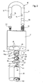
- the Fig. 1 and 2 show a lock body 2, which has at its upper end face two holes 4, in which the two legs 6, 8 of a bracket 10 can be inserted.
- the leg 6 is formed longer than the leg 8 and, when it is in the lock body 2, under bias of a compression spring 12 which moves the bracket 10 in its unlocked open position, if it is not retained by other forces.
- Both legs 6, 8 of the bracket 10 have at the same height on their inner side in each case a recess 14 into which engages in the locked state of the padlock each designed as a closing ball 16 locking element with a portion.
- locking balls 16 may alternatively be used differently shaped locking elements.
- the longer leg 9 also has between its lock body end and its recess 14 a constriction 68, which preferably over the entire circumference of the leg 6 extends.
- lock body 2 On its underside and opposite the holes 4 of the lock body 2 has two overlapping holes 18 which are dimensioned so that a lock cylinder 20 can be inserted into this from below.
- This lock cylinder 20 can be secured in the usual way with the bracket 10 open in the lock body 2 by means of a screw 22.
- a trained as a ball valve slide 24 is used, which has a substantially cylindrical shape and at its outer periphery two opposing recesses 26 which form a control link for the closing balls 16 in the usual way ,
- the said control link is at a rotation of the ball valve about its central axis capable of moving the closing balls 16 in its locking position in the recesses 14 of the bracket 10 or release a movement of the closing balls 16 from the recesses 14 out.
- the ball valve has at its outer periphery also has an additional recess 26a, whose radial depth is dimensioned larger as that of the opposing recesses 26.
- the function of the additional recess 26a will be explained later.
- the ball valve 24 On its underside, the ball valve 24 has two quarter-circle in cross section engagement elements 28, 28 ', which are arranged symmetrically to the central axis of rotation of the ball valve 24.
- the coil spring 30 is inserted such that its inwardly projecting extension 32 on the engaging member 28 'is supported and its outwardly projecting extension 34 is fixed in a suitable manner in the lock body 2, that he himself can not move relative to the lock body 2. Consequently, a rotational movement of the ball valve 24 in a clockwise movement (based on Fig. 2 ) to a entrainment of the extension 32 by the engagement member 28 'and thus to a tensioning of the coil spring 30th
- the inventive locking plate 36 is inserted into the openings 18 and pressed there, so that they can not move relative to the lock body 2.
- the pressing takes place in a position in which a tensioning or relaxing the coil spring 30 is not hindered by friction.
- the locking plate 36 has a radially beyond the circumference protruding against rotation 38, which reliably prevents twisting thereof in the lock body 2 pressed locking plate 36 about the axis of rotation of the ball slide 24.
- the blocking plate 36 has a central opening 40, which has approximately a part-circular shape, wherein the pitch circle encloses an angle of approximately 240 °.
- the portion 42 of the locking plate 36 which is not associated with the opening 40 and the opening 40 to a Correspondingly, the circle would be approximately at an angle of 120 °, with the tip of this region 42 lying in the radial direction slightly outside the center of the opening 40, so that the opening 40 does not form an exact pitch, but rather is slightly larger than one.
- a coupling 44 may be inserted through the aperture 40 if needed in the manner hereinafter explained, which ultimately comes to lie between the engagement elements 28, 28 '.
- the coupling piece 44 has a substantially Z-shape with a center piece 46 and two of them substantially perpendicular protruding legs 48, 48 '.
- the coupling piece 44 is usually first coupled to the lock cylinder 20 and then used together with this in the lock body 2.
- the cylinder core 50 of the lock cylinder 20 has on its end facing the ball valve 24 a substantially U-shaped driver element 52 which in turn has two projecting in the direction of the ball slide 24 driver 54, 54 'has (see Fig. 1 ).
- the two drivers 54, 54 ' have a substantially square cross section and define therebetween a gap in which the center piece 46 of the coupling piece 44 can be accommodated, so that in this case after inserting the lock cylinder 20 with the coupling piece 44 at a Rotary movement of the cylinder core 50, the driver 54, 54 'rotate together with the coupling piece 44.
- the lock cylinder 20 After insertion of the lock cylinder 20, this is fixed by means of the screw 22 in the lock body 2, whereupon the padlock is completely assembled. If necessary, the lock cylinder 20 by a Loosen the screw 22 in the unlocked position of the padlock readily be removed again from the lock body 2. An optionally inserted coupling piece 44 can then also be removed in order to change the padlock from closing constraint to automatic function. Likewise, the lock cylinder 20 can of course also be removed in order to insert a previously non-existing coupling piece 44 through the opening 40 of the locking plate 36 into the padlock, so as to make a switch from automatic to forced closing. In such Umstellvorrudn the coil spring 30 and the ball valve 24 can not fall out of the lock body 2, since they are secured there by the inventive locking plate 36.
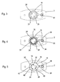
- Fig. 3 shows a view of the lock body 2 according to the Fig. 1 and 2 from below, in which case a further small bore 56 can be seen here in the region of the holes 18, through which the screw 22 for fixing the lock cylinder 20 into a thread 59 present therein (see FIG Fig. 1 ) can be screwed.
- the coil spring 30 is inserted, care must be taken that the inner extension 32 of the coil spring 30 is supported on the engaging member 28 ', so that a movement of the ball valve 24 in a clockwise direction to a entrainment of the extension 32 by the engagement member 28th ' leads.
- the outer extension 34 of the coil spring 30 is fixed in a correspondingly configured recess 58 in the lock body 2, so that this extension can either not at all or only slightly move in the lock body.
- Fig. 5 introduced the locking plate 36 of the invention in the holes 18.
- the blocking plate 36 has in its embodiment according to Fig. 5 at its outer periphery a toothing 60, which allows a particularly good compression of the locking plate 36 in the holes 18.
- the opening 40 of the lock plate is formed as in connection with the Fig. 1 and 2 already explained.
- the radially outwardly projecting anti-rotation 38 of the locking plate 36 engages in the same recess 58, in which already the outwardly projecting extension 34 of the coil spring 30 has been introduced.
- the driver 54, 54 'and thus the driver 52 at least partially move in the plane of coil spring 30 and engaging elements 28, 28'. Since the engagement elements 28, 28 'and the drivers 54, 54' extending through the opening 40 are then at least partly in the same plane, they can abut one another during a rotational movement of the cylinder core 50 of the lock cylinder 20, such that a rotational movement of the cylinder core 50 occurs the ball valve 24 can be transferred.
- the driver element 52 When the cylinder core 50 is in its locked position in which an inserted key can be removed, the driver element 52 is in its in Fig. 6 illustrated position in which the coil spring 30 biases the engagement element 28 'and thus also the engagement element 28 against the drivers 54, 54' of the driver element 52. In this position are according to Fig. 7 the closing balls 16 into engagement with the recesses 14 of the bracket 10, wherein a movement of the closing balls 16 is blocked out of these recesses 14 out through the guide slot of the ball slide 24. Thus, the padlock is reliably locked in this position.
- the cam member 52 In this open position of the padlock, the cam member 52 abuts a stop surface 62 of the lock plate 36, so that the lock plate ultimately limits movement of the cam member 52 to its unlocked position. In a corresponding manner, the stop surface 64 ( Fig. 6 ) the movement of the driver 52 in its locked position.
- Fig. 8 shows that between the driver element 52 and its drivers 54, 54 'and the engagement elements 28, 28' is a game, which allows the driver element 52, starting from the in Fig. 8 shown position back to the position according to Fig. 6 can be rotated without the engagement elements 28, 28 'and the ball valve 24 move.
- This position is in Fig. 10 shown. In this position, the padlock is still in its open position according to Fig. 9 However, it is possible to remove a key from the cylinder core 50, as the cylinder core regardless of the ball valve 24 back in its locking position according to the 6 and 7 located.
- Fig. 11 now shows a situation in which the ball valve 24 in its unlocked position according to Fig. 8 is located so that the opening 40 of the locking plate 36 exclusively by the one engaging element 28 of the Ball slide is reduced, since the other engagement element 28 'is behind the region 42 of the locking plate 36.
- the reduced by the engagement member 28 opening 40 of the locking plate 36 is sufficiently large that the coupling piece 44 can be moved through this opening 40 until it is in the plane of the engaging elements 28, 28 '.
- the coupling piece 44 has a center piece 46 from which two legs 48, 48 'protrude at right angles.
- the two relative to the center piece 46 outer edge regions of the legs 48, 48 ' have a circular arc shape, wherein the radius of these circular arcs is smaller than the radius of the opening 40 of the locking plate 36.
- the middle piece 46 has in the region of the leg 48' a bevel, so that the coupling piece 44 does not abut against the abutment surface 64 of the blocking plate 36 in its generally occurring together with the lock cylinder 20 insertion.
- the lock cylinder 20 can be bolted to the lock body 2 via the screw 22.
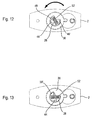
- the driver element 52 passes into his in Fig. 12 shown position in which the drivers 54, 54 'of the driver 52 come to lie on either side of the central portion 46 of the coupling piece 44.
- Fig. 12 shows very clearly that when inserted into the lock body 2 lock cylinder 20, the two legs 48, 48 'of the coupling piece 44, the clearance between driver element 52 and engaging elements 28, 28' largely eliminate, so that the driver element 52 is not in the direction of the arrow Fig. 12 can be rotated without taking the engaging elements 28, 28 'and the ball valve 24. insofar performs a rotation of the cylinder core 50 and the driver 52 in the direction of the arrow according to Fig. 12 inevitably to the fact that the ball valve 24 is rotated in its locking position. However, such a twist is only possible after the bracket 10 has been fully inserted into the lock body 2, so that a key from the cylinder core 50 can only be removed when the padlock is actually locked.
- Fig. 14 shows the padlock according to the Fig. 1 to 13
- the ball valve 24 is in such a position that the closing balls 16 in the two opposing recesses 26 (see Fig. 1 engage, so that the closing balls 16, the recesses 14 of the legs 6, 8 of the bracket 10 release, which causes the bracket 10 as far as moved out of the lock body 2 by the compression spring 12, as shown in Fig. 14 is shown.
- the right-to-see closing ball 16 is engaged with the constriction 68 of the longer leg 6 of the bracket 10 and thus prevents this longer leg 6 can be completely detached from the lock body 2.
- Fig. 14 the curtain lock according to the invention is shown after the lock cylinder 20 ( Fig. 1 ) has been removed from the lock body 2. Instead of the lock cylinder 20 is according to Fig. 14 now a tool 70 introduced into the opening of the lock body 2 provided for the lock cylinder 20.
- the front end portion of the tool 70 is in Fig. 16 shown schematically. It has a cylindrical portion 72 whose diameter is dimensioned slightly larger than the diameter of the lock cylinder core 50 (FIG. Fig. 1 ), so that this cylindrical portion 72 is well guided or stored in the lock body 2.
- the cylindrical portion 72 tapers in its forward end portion and merges into a T-shaped portion 74 having a transverse leg 76 which extends transversely to the longitudinal axis of the tool 70.
- This transverse leg 76 is according to Fig. 14 as far as passed through the opening 40 of the locking plate 36 until the end portions of the transverse leg 76 in abutment with the engaging elements 28, 28 'of the ball valve 24 are.
- the tool 70 can be rotated clockwise, so that the ball valve 24 completes this rotation and is "overrun".
- This over-rotation causes the deeper recess 26a (FIG. Fig. 1 . Fig. 14 ) of the ball valve 24 in engagement with the in the FIGS. 14 and 15 right shown closing ball 16 passes.
- this closing ball 16 can then move so far in the lock body 2 inward that it releases the constriction 68, so that the longer leg 6 of the bracket 10 completely moved past the closing ball 16 and can be removed from the lock body 2.
- Fig. 1 to 15 thus show a curtain lock according to the invention, which at the same time allows both a replacement of the bracket and a switch between automatic function and Sch.zwang while offering the advantages of the invention.
Landscapes
- Refuge Islands, Traffic Blockers, Or Guard Fence (AREA)
- Pivots And Pivotal Connections (AREA)
- Lock And Its Accessories (AREA)
Applications Claiming Priority (1)
| Application Number | Priority Date | Filing Date | Title |
|---|---|---|---|
| DE200910023561 DE102009023561A1 (de) | 2009-06-02 | 2009-06-02 | Vorhangschloss |
Publications (3)
| Publication Number | Publication Date |
|---|---|
| EP2261447A2 true EP2261447A2 (fr) | 2010-12-15 |
| EP2261447A3 EP2261447A3 (fr) | 2014-10-29 |
| EP2261447B1 EP2261447B1 (fr) | 2015-09-30 |
Family
ID=42830180
Family Applications (1)
| Application Number | Title | Priority Date | Filing Date |
|---|---|---|---|
| EP10005359.4A Active EP2261447B1 (fr) | 2009-06-02 | 2010-05-21 | Cadenas |
Country Status (8)
| Country | Link |
|---|---|
| US (1) | US9689179B2 (fr) |
| EP (1) | EP2261447B1 (fr) |
| CN (1) | CN102031905B (fr) |
| AU (1) | AU2010202189B2 (fr) |
| CA (1) | CA2706246C (fr) |
| DE (1) | DE102009023561A1 (fr) |
| DK (1) | DK2261447T3 (fr) |
| NZ (1) | NZ585758A (fr) |
Cited By (2)
| Publication number | Priority date | Publication date | Assignee | Title |
|---|---|---|---|---|
| WO2022073854A1 (fr) * | 2020-10-06 | 2022-04-14 | ABUS August Bremicker Söhne KG | Kit d'assemblage de base de cadenas et système de cadenas |
| EP3914793A4 (fr) * | 2019-01-25 | 2023-02-22 | Noke, Inc. | Verrou électronique et anses interchangeables |
Families Citing this family (11)
| Publication number | Priority date | Publication date | Assignee | Title |
|---|---|---|---|---|
| ITFI20130193A1 (it) * | 2013-08-08 | 2015-02-09 | Metalplus S P A | Un lucchetto con il meccanismo di apertura integrato nel cilindro |
| DE102013222256A1 (de) | 2013-10-31 | 2015-04-30 | ABUS August Bremicker Söhne KG | Hangschloss |
| TWI571557B (zh) * | 2014-06-27 | 2017-02-21 | 周鑫軾 | 可更換鎖心的掛鎖 |
| CN106013963A (zh) * | 2016-06-24 | 2016-10-12 | 黄林 | 一种304不锈钢防盗锁 |
| DE102016125283A1 (de) | 2016-12-21 | 2018-06-21 | ABUS August Bremicker Söhne KG | Hangschloss |
| ES2934588T3 (es) | 2018-04-03 | 2023-02-23 | Knox Ass Inc Dba Knox Company | Protector y absorbedor de fluidos para dispositivos de bloqueo |
| DE102018109746A1 (de) * | 2018-04-23 | 2019-10-24 | ABUS August Bremicker Söhne KG | Hangschloss zum sichern eines schalters |
| USD905533S1 (en) * | 2018-09-26 | 2020-12-22 | Boxlock, Inc. | Electronic lock housing base portion |
| USD902008S1 (en) * | 2018-09-27 | 2020-11-17 | ABUS August Bremicker Söhne KG | Padlock |
| US11346134B2 (en) * | 2019-02-06 | 2022-05-31 | Brady Worldwide, Inc. | Lock with integrated cam |
| CN110541611B (zh) * | 2019-09-29 | 2024-06-04 | 义乌市长浩锁业有限公司 | 一种挂锁组装中锁体的定位机构 |
Citations (2)
| Publication number | Priority date | Publication date | Assignee | Title |
|---|---|---|---|---|
| US5363678A (en) | 1993-04-09 | 1994-11-15 | Abus August Bremicker Sohne Kg | Padlock with ball-locked shackle |
| US5377511A (en) | 1993-07-15 | 1995-01-03 | Abus August Bremicker Sohne Kg | Padlock with locking balls for a shackle |
Family Cites Families (11)
| Publication number | Priority date | Publication date | Assignee | Title |
|---|---|---|---|---|
| US4998422A (en) * | 1989-08-30 | 1991-03-12 | Best Lock Corporation | Removable core padlock with bolt retainer |
| US5174136A (en) * | 1991-10-04 | 1992-12-29 | Thwing Randy L | Dual function padlock with removable cylinder mechanism |
| US6145356A (en) * | 1999-01-11 | 2000-11-14 | Thwing; Randy L. | Dual-function locks and sub-assemblies therefor |
| US20020078720A1 (en) * | 2000-06-15 | 2002-06-27 | Watts John Russell | Padlocks |
| GB2364348B (en) * | 2000-06-15 | 2004-11-24 | Austral Lock Ind Pty Ltd | Padlocks |
| US20030041630A1 (en) * | 2001-08-31 | 2003-03-06 | Laitala Daniel A. | Rekeyable lock with circumferential pin configuration |
| US6766673B2 (en) * | 2001-09-21 | 2004-07-27 | Hampton Products International Corporation | Padlock |
| US7278283B2 (en) * | 2004-04-27 | 2007-10-09 | Abus August Bremicker Soehne Kg | Padlock |
| DE602005025629D1 (de) * | 2004-04-29 | 2011-02-10 | Celesia Pty Ltd | Vorhängeschloss mit und ohne schlüsselrückhaltungs- (und schnapp-schloss-) merkmal |
| WO2007019639A1 (fr) | 2005-08-18 | 2007-02-22 | Assa Abloy Australia Pty Limited | Cadenas comportant un arceau amovible |
| CN101029548B (zh) * | 2006-03-02 | 2011-02-09 | 川斯海洋集团有限公司 | 可快速更换锁钩的挂锁 |
-
2009
- 2009-06-02 DE DE200910023561 patent/DE102009023561A1/de not_active Withdrawn
-
2010
- 2010-05-21 DK DK10005359.4T patent/DK2261447T3/en active
- 2010-05-21 EP EP10005359.4A patent/EP2261447B1/fr active Active
- 2010-05-27 US US12/788,700 patent/US9689179B2/en active Active
- 2010-05-28 NZ NZ585758A patent/NZ585758A/en unknown
- 2010-05-28 AU AU2010202189A patent/AU2010202189B2/en active Active
- 2010-06-01 CA CA2706246A patent/CA2706246C/fr active Active
- 2010-06-01 CN CN201010191710.9A patent/CN102031905B/zh active Active
Patent Citations (2)
| Publication number | Priority date | Publication date | Assignee | Title |
|---|---|---|---|---|
| US5363678A (en) | 1993-04-09 | 1994-11-15 | Abus August Bremicker Sohne Kg | Padlock with ball-locked shackle |
| US5377511A (en) | 1993-07-15 | 1995-01-03 | Abus August Bremicker Sohne Kg | Padlock with locking balls for a shackle |
Cited By (3)
| Publication number | Priority date | Publication date | Assignee | Title |
|---|---|---|---|---|
| EP3914793A4 (fr) * | 2019-01-25 | 2023-02-22 | Noke, Inc. | Verrou électronique et anses interchangeables |
| WO2022073854A1 (fr) * | 2020-10-06 | 2022-04-14 | ABUS August Bremicker Söhne KG | Kit d'assemblage de base de cadenas et système de cadenas |
| US12241286B2 (en) | 2020-10-06 | 2025-03-04 | Abus August Bremicker Sohne Kg | Padlock basic assembly kit and padlock system |
Also Published As
| Publication number | Publication date |
|---|---|
| AU2010202189B2 (en) | 2014-09-18 |
| CN102031905B (zh) | 2015-05-13 |
| EP2261447B1 (fr) | 2015-09-30 |
| DK2261447T3 (en) | 2016-01-04 |
| AU2010202189A1 (en) | 2010-12-16 |
| US20100300165A1 (en) | 2010-12-02 |
| CA2706246A1 (fr) | 2010-12-02 |
| US9689179B2 (en) | 2017-06-27 |
| CA2706246C (fr) | 2017-01-24 |
| NZ585758A (en) | 2010-10-29 |
| CN102031905A (zh) | 2011-04-27 |
| EP2261447A3 (fr) | 2014-10-29 |
| DE102009023561A1 (de) | 2010-12-09 |
Similar Documents
| Publication | Publication Date | Title |
|---|---|---|
| EP2261447B1 (fr) | Cadenas | |
| DE69711299T2 (de) | Karabinerhaken mit Verriegelungsvorrichtung | |
| EP3256089B1 (fr) | Mâchoire de serrage destinée à être montée sur une glissière d'une table d'opération | |
| EP1743994B1 (fr) | Serrure pour sortie de secours | |
| EP1443295B1 (fr) | Pistolet avec dispositif de sécurité | |
| EP2019178A2 (fr) | Serrure à barres articulées | |
| EP3153648B1 (fr) | Cadenas | |
| EP0369107A2 (fr) | Serrure cylindrique | |
| EP1274908B1 (fr) | Verrou destine a etre monte dans une ouverture pratiquee dans une paroi mince | |
| DE4100374A1 (de) | Loesbarer verriegelungsmechanismus | |
| EP1077174A2 (fr) | Serrure pour frein à disque | |
| DE102008029686B4 (de) | Schließzylinder mit selbsttätiger Rückstellung des Schließgliedes | |
| DE29610293U1 (de) | Karabinerhaken | |
| DE202008004598U1 (de) | Beschlag für Fenster oder Türen | |
| EP3517713B1 (fr) | Dispositif de fermeture | |
| EP0036141B1 (fr) | Dispositif d'arrêt actionné par une clé | |
| EP2317164B1 (fr) | Crochet, notamment pour dispositifs de sécurité | |
| DE102005037194B4 (de) | Schließzylinder, insbesondere Profilzylinder, für eine Schließvorrichtung wie z.B. ein Türschloss | |
| EP1116838A1 (fr) | Ferrure de protection pour porte | |
| AT504131B1 (de) | Beschlag | |
| DE3107606A1 (de) | Zweiteiliger drueckerstift | |
| DE4117354C2 (de) | Drehstangenschloß | |
| DE102016106404A1 (de) | Verbesserter Schließzylinder | |
| EP2363679B1 (fr) | Arme de tir, notamment arme de chasse | |
| DE19920178A1 (de) | Schließzylinder mit auswechselbarem Zylinderkern |
Legal Events
| Date | Code | Title | Description |
|---|---|---|---|
| PUAI | Public reference made under article 153(3) epc to a published international application that has entered the european phase |
Free format text: ORIGINAL CODE: 0009012 |
|
| AK | Designated contracting states |
Kind code of ref document: A2 Designated state(s): AL AT BE BG CH CY CZ DE DK EE ES FI FR GB GR HR HU IE IS IT LI LT LU LV MC MK MT NL NO PL PT RO SE SI SK SM TR |
|
| AX | Request for extension of the european patent |
Extension state: BA ME RS |
|
| PUAL | Search report despatched |
Free format text: ORIGINAL CODE: 0009013 |
|
| AK | Designated contracting states |
Kind code of ref document: A3 Designated state(s): AL AT BE BG CH CY CZ DE DK EE ES FI FR GB GR HR HU IE IS IT LI LT LU LV MC MK MT NL NO PL PT RO SE SI SK SM TR |
|
| AX | Request for extension of the european patent |
Extension state: BA ME RS |
|
| RIC1 | Information provided on ipc code assigned before grant |
Ipc: E05B 67/24 20060101AFI20140919BHEP |
|
| 17P | Request for examination filed |
Effective date: 20150401 |
|
| RBV | Designated contracting states (corrected) |
Designated state(s): AL AT BE BG CH CY CZ DE DK EE ES FI FR GB GR HR HU IE IS IT LI LT LU LV MC MK MT NL NO PL PT RO SE SI SK SM TR |
|
| GRAP | Despatch of communication of intention to grant a patent |
Free format text: ORIGINAL CODE: EPIDOSNIGR1 |
|
| INTG | Intention to grant announced |
Effective date: 20150526 |
|
| GRAS | Grant fee paid |
Free format text: ORIGINAL CODE: EPIDOSNIGR3 |
|
| GRAA | (expected) grant |
Free format text: ORIGINAL CODE: 0009210 |
|
| AK | Designated contracting states |
Kind code of ref document: B1 Designated state(s): AL AT BE BG CH CY CZ DE DK EE ES FI FR GB GR HR HU IE IS IT LI LT LU LV MC MK MT NL NO PL PT RO SE SI SK SM TR |
|
| REG | Reference to a national code |
Ref country code: CH Ref legal event code: EP Ref country code: GB Ref legal event code: FG4D Free format text: NOT ENGLISH |
|
| REG | Reference to a national code |
Ref country code: AT Ref legal event code: REF Ref document number: 752527 Country of ref document: AT Kind code of ref document: T Effective date: 20151015 |
|
| REG | Reference to a national code |
Ref country code: IE Ref legal event code: FG4D Free format text: LANGUAGE OF EP DOCUMENT: GERMAN |
|
| REG | Reference to a national code |
Ref country code: DE Ref legal event code: R096 Ref document number: 502010010369 Country of ref document: DE |
|
| REG | Reference to a national code |
Ref country code: SE Ref legal event code: TRGR |
|
| REG | Reference to a national code |
Ref country code: DK Ref legal event code: T3 Effective date: 20160103 |
|
| PG25 | Lapsed in a contracting state [announced via postgrant information from national office to epo] |
Ref country code: LT Free format text: LAPSE BECAUSE OF FAILURE TO SUBMIT A TRANSLATION OF THE DESCRIPTION OR TO PAY THE FEE WITHIN THE PRESCRIBED TIME-LIMIT Effective date: 20150930 Ref country code: FI Free format text: LAPSE BECAUSE OF FAILURE TO SUBMIT A TRANSLATION OF THE DESCRIPTION OR TO PAY THE FEE WITHIN THE PRESCRIBED TIME-LIMIT Effective date: 20150930 Ref country code: NO Free format text: LAPSE BECAUSE OF FAILURE TO SUBMIT A TRANSLATION OF THE DESCRIPTION OR TO PAY THE FEE WITHIN THE PRESCRIBED TIME-LIMIT Effective date: 20151230 Ref country code: LV Free format text: LAPSE BECAUSE OF FAILURE TO SUBMIT A TRANSLATION OF THE DESCRIPTION OR TO PAY THE FEE WITHIN THE PRESCRIBED TIME-LIMIT Effective date: 20150930 |
|
| REG | Reference to a national code |
Ref country code: NL Ref legal event code: MP Effective date: 20150930 |
|
| REG | Reference to a national code |
Ref country code: LT Ref legal event code: MG4D |
|
| PG25 | Lapsed in a contracting state [announced via postgrant information from national office to epo] |
Ref country code: HR Free format text: LAPSE BECAUSE OF FAILURE TO SUBMIT A TRANSLATION OF THE DESCRIPTION OR TO PAY THE FEE WITHIN THE PRESCRIBED TIME-LIMIT Effective date: 20150930 |
|
| PG25 | Lapsed in a contracting state [announced via postgrant information from national office to epo] |
Ref country code: CZ Free format text: LAPSE BECAUSE OF FAILURE TO SUBMIT A TRANSLATION OF THE DESCRIPTION OR TO PAY THE FEE WITHIN THE PRESCRIBED TIME-LIMIT Effective date: 20150930 Ref country code: ES Free format text: LAPSE BECAUSE OF FAILURE TO SUBMIT A TRANSLATION OF THE DESCRIPTION OR TO PAY THE FEE WITHIN THE PRESCRIBED TIME-LIMIT Effective date: 20150930 Ref country code: SK Free format text: LAPSE BECAUSE OF FAILURE TO SUBMIT A TRANSLATION OF THE DESCRIPTION OR TO PAY THE FEE WITHIN THE PRESCRIBED TIME-LIMIT Effective date: 20150930 Ref country code: IS Free format text: LAPSE BECAUSE OF FAILURE TO SUBMIT A TRANSLATION OF THE DESCRIPTION OR TO PAY THE FEE WITHIN THE PRESCRIBED TIME-LIMIT Effective date: 20160130 Ref country code: NL Free format text: LAPSE BECAUSE OF FAILURE TO SUBMIT A TRANSLATION OF THE DESCRIPTION OR TO PAY THE FEE WITHIN THE PRESCRIBED TIME-LIMIT Effective date: 20150930 Ref country code: IT Free format text: LAPSE BECAUSE OF FAILURE TO SUBMIT A TRANSLATION OF THE DESCRIPTION OR TO PAY THE FEE WITHIN THE PRESCRIBED TIME-LIMIT Effective date: 20150930 Ref country code: EE Free format text: LAPSE BECAUSE OF FAILURE TO SUBMIT A TRANSLATION OF THE DESCRIPTION OR TO PAY THE FEE WITHIN THE PRESCRIBED TIME-LIMIT Effective date: 20150930 |
|
| REG | Reference to a national code |
Ref country code: FR Ref legal event code: PLFP Year of fee payment: 7 |
|
| PG25 | Lapsed in a contracting state [announced via postgrant information from national office to epo] |
Ref country code: RO Free format text: LAPSE BECAUSE OF FAILURE TO SUBMIT A TRANSLATION OF THE DESCRIPTION OR TO PAY THE FEE WITHIN THE PRESCRIBED TIME-LIMIT Effective date: 20150930 Ref country code: PL Free format text: LAPSE BECAUSE OF FAILURE TO SUBMIT A TRANSLATION OF THE DESCRIPTION OR TO PAY THE FEE WITHIN THE PRESCRIBED TIME-LIMIT Effective date: 20150930 Ref country code: PT Free format text: LAPSE BECAUSE OF FAILURE TO SUBMIT A TRANSLATION OF THE DESCRIPTION OR TO PAY THE FEE WITHIN THE PRESCRIBED TIME-LIMIT Effective date: 20160201 |
|
| REG | Reference to a national code |
Ref country code: DE Ref legal event code: R097 Ref document number: 502010010369 Country of ref document: DE |
|
| PLBE | No opposition filed within time limit |
Free format text: ORIGINAL CODE: 0009261 |
|
| STAA | Information on the status of an ep patent application or granted ep patent |
Free format text: STATUS: NO OPPOSITION FILED WITHIN TIME LIMIT |
|
| PG25 | Lapsed in a contracting state [announced via postgrant information from national office to epo] |
Ref country code: BE Free format text: LAPSE BECAUSE OF NON-PAYMENT OF DUE FEES Effective date: 20160531 |
|
| 26N | No opposition filed |
Effective date: 20160701 |
|
| PG25 | Lapsed in a contracting state [announced via postgrant information from national office to epo] |
Ref country code: SI Free format text: LAPSE BECAUSE OF FAILURE TO SUBMIT A TRANSLATION OF THE DESCRIPTION OR TO PAY THE FEE WITHIN THE PRESCRIBED TIME-LIMIT Effective date: 20150930 |
|
| PG25 | Lapsed in a contracting state [announced via postgrant information from national office to epo] |
Ref country code: LU Free format text: LAPSE BECAUSE OF FAILURE TO SUBMIT A TRANSLATION OF THE DESCRIPTION OR TO PAY THE FEE WITHIN THE PRESCRIBED TIME-LIMIT Effective date: 20160521 |
|
| REG | Reference to a national code |
Ref country code: CH Ref legal event code: PL |
|
| PG25 | Lapsed in a contracting state [announced via postgrant information from national office to epo] |
Ref country code: CH Free format text: LAPSE BECAUSE OF NON-PAYMENT OF DUE FEES Effective date: 20160531 Ref country code: LI Free format text: LAPSE BECAUSE OF NON-PAYMENT OF DUE FEES Effective date: 20160531 |
|
| REG | Reference to a national code |
Ref country code: IE Ref legal event code: MM4A |
|
| REG | Reference to a national code |
Ref country code: FR Ref legal event code: PLFP Year of fee payment: 8 |
|
| PG25 | Lapsed in a contracting state [announced via postgrant information from national office to epo] |
Ref country code: IE Free format text: LAPSE BECAUSE OF NON-PAYMENT OF DUE FEES Effective date: 20160521 |
|
| REG | Reference to a national code |
Ref country code: AT Ref legal event code: MM01 Ref document number: 752527 Country of ref document: AT Kind code of ref document: T Effective date: 20160521 |
|
| PG25 | Lapsed in a contracting state [announced via postgrant information from national office to epo] |
Ref country code: AT Free format text: LAPSE BECAUSE OF NON-PAYMENT OF DUE FEES Effective date: 20160521 |
|
| REG | Reference to a national code |
Ref country code: FR Ref legal event code: PLFP Year of fee payment: 9 |
|
| PG25 | Lapsed in a contracting state [announced via postgrant information from national office to epo] |
Ref country code: HU Free format text: LAPSE BECAUSE OF FAILURE TO SUBMIT A TRANSLATION OF THE DESCRIPTION OR TO PAY THE FEE WITHIN THE PRESCRIBED TIME-LIMIT; INVALID AB INITIO Effective date: 20100521 Ref country code: SM Free format text: LAPSE BECAUSE OF FAILURE TO SUBMIT A TRANSLATION OF THE DESCRIPTION OR TO PAY THE FEE WITHIN THE PRESCRIBED TIME-LIMIT Effective date: 20150930 Ref country code: CY Free format text: LAPSE BECAUSE OF FAILURE TO SUBMIT A TRANSLATION OF THE DESCRIPTION OR TO PAY THE FEE WITHIN THE PRESCRIBED TIME-LIMIT Effective date: 20150930 |
|
| PG25 | Lapsed in a contracting state [announced via postgrant information from national office to epo] |
Ref country code: MT Free format text: LAPSE BECAUSE OF FAILURE TO SUBMIT A TRANSLATION OF THE DESCRIPTION OR TO PAY THE FEE WITHIN THE PRESCRIBED TIME-LIMIT Effective date: 20150930 Ref country code: TR Free format text: LAPSE BECAUSE OF FAILURE TO SUBMIT A TRANSLATION OF THE DESCRIPTION OR TO PAY THE FEE WITHIN THE PRESCRIBED TIME-LIMIT Effective date: 20150930 Ref country code: GR Free format text: LAPSE BECAUSE OF FAILURE TO SUBMIT A TRANSLATION OF THE DESCRIPTION OR TO PAY THE FEE WITHIN THE PRESCRIBED TIME-LIMIT Effective date: 20150930 Ref country code: MC Free format text: LAPSE BECAUSE OF FAILURE TO SUBMIT A TRANSLATION OF THE DESCRIPTION OR TO PAY THE FEE WITHIN THE PRESCRIBED TIME-LIMIT Effective date: 20150930 Ref country code: MK Free format text: LAPSE BECAUSE OF FAILURE TO SUBMIT A TRANSLATION OF THE DESCRIPTION OR TO PAY THE FEE WITHIN THE PRESCRIBED TIME-LIMIT Effective date: 20150930 |
|
| PG25 | Lapsed in a contracting state [announced via postgrant information from national office to epo] |
Ref country code: BG Free format text: LAPSE BECAUSE OF FAILURE TO SUBMIT A TRANSLATION OF THE DESCRIPTION OR TO PAY THE FEE WITHIN THE PRESCRIBED TIME-LIMIT Effective date: 20150930 |
|
| PG25 | Lapsed in a contracting state [announced via postgrant information from national office to epo] |
Ref country code: AL Free format text: LAPSE BECAUSE OF FAILURE TO SUBMIT A TRANSLATION OF THE DESCRIPTION OR TO PAY THE FEE WITHIN THE PRESCRIBED TIME-LIMIT Effective date: 20150930 |
|
| PGFP | Annual fee paid to national office [announced via postgrant information from national office to epo] |
Ref country code: DE Payment date: 20250729 Year of fee payment: 16 |
|
| PGFP | Annual fee paid to national office [announced via postgrant information from national office to epo] |
Ref country code: GB Payment date: 20260521 Year of fee payment: 17 Ref country code: DK Payment date: 20260522 Year of fee payment: 17 |
|
| PGFP | Annual fee paid to national office [announced via postgrant information from national office to epo] |
Ref country code: SE Payment date: 20260520 Year of fee payment: 17 |
|
| PGFP | Annual fee paid to national office [announced via postgrant information from national office to epo] |
Ref country code: FR Payment date: 20260526 Year of fee payment: 17 |