EP0733414B1 - Herstellungsverfahren eines Metallbehälters in einer Form - Google Patents
Herstellungsverfahren eines Metallbehälters in einer Form Download PDFInfo
- Publication number
- EP0733414B1 EP0733414B1 EP96400484A EP96400484A EP0733414B1 EP 0733414 B1 EP0733414 B1 EP 0733414B1 EP 96400484 A EP96400484 A EP 96400484A EP 96400484 A EP96400484 A EP 96400484A EP 0733414 B1 EP0733414 B1 EP 0733414B1
- Authority
- EP
- European Patent Office
- Prior art keywords
- zone
- expanded
- expansion
- peripheral skirt
- elementary
- Prior art date
- Legal status (The legal status is an assumption and is not a legal conclusion. Google has not performed a legal analysis and makes no representation as to the accuracy of the status listed.)
- Expired - Lifetime
Links
- 238000000034 method Methods 0.000 title claims description 37
- 229910052751 metal Inorganic materials 0.000 title claims description 25
- 239000002184 metal Substances 0.000 title claims description 25
- 238000004519 manufacturing process Methods 0.000 title claims description 9
- 239000000463 material Substances 0.000 claims abstract description 7
- 229920001971 elastomer Polymers 0.000 claims abstract description 5
- 239000000806 elastomer Substances 0.000 claims abstract description 5
- 230000002093 peripheral effect Effects 0.000 claims description 55
- 241000735470 Juncus Species 0.000 description 9
- 230000015572 biosynthetic process Effects 0.000 description 9
- IJGRMHOSHXDMSA-UHFFFAOYSA-N Atomic nitrogen Chemical compound N#N IJGRMHOSHXDMSA-UHFFFAOYSA-N 0.000 description 7
- 238000010409 ironing Methods 0.000 description 7
- PXHVJJICTQNCMI-UHFFFAOYSA-N Nickel Chemical compound [Ni] PXHVJJICTQNCMI-UHFFFAOYSA-N 0.000 description 4
- 229910052782 aluminium Inorganic materials 0.000 description 4
- XAGFODPZIPBFFR-UHFFFAOYSA-N aluminium Chemical compound [Al] XAGFODPZIPBFFR-UHFFFAOYSA-N 0.000 description 4
- 229910001209 Low-carbon steel Inorganic materials 0.000 description 3
- 229910000831 Steel Inorganic materials 0.000 description 3
- 229910052757 nitrogen Inorganic materials 0.000 description 3
- 239000010959 steel Substances 0.000 description 3
- 229910000838 Al alloy Inorganic materials 0.000 description 2
- OKTJSMMVPCPJKN-UHFFFAOYSA-N Carbon Chemical compound [C] OKTJSMMVPCPJKN-UHFFFAOYSA-N 0.000 description 2
- VYZAMTAEIAYCRO-UHFFFAOYSA-N Chromium Chemical compound [Cr] VYZAMTAEIAYCRO-UHFFFAOYSA-N 0.000 description 2
- RYGMFSIKBFXOCR-UHFFFAOYSA-N Copper Chemical compound [Cu] RYGMFSIKBFXOCR-UHFFFAOYSA-N 0.000 description 2
- PWHULOQIROXLJO-UHFFFAOYSA-N Manganese Chemical compound [Mn] PWHULOQIROXLJO-UHFFFAOYSA-N 0.000 description 2
- OAICVXFJPJFONN-UHFFFAOYSA-N Phosphorus Chemical compound [P] OAICVXFJPJFONN-UHFFFAOYSA-N 0.000 description 2
- XUIMIQQOPSSXEZ-UHFFFAOYSA-N Silicon Chemical compound [Si] XUIMIQQOPSSXEZ-UHFFFAOYSA-N 0.000 description 2
- NINIDFKCEFEMDL-UHFFFAOYSA-N Sulfur Chemical compound [S] NINIDFKCEFEMDL-UHFFFAOYSA-N 0.000 description 2
- 229910052799 carbon Inorganic materials 0.000 description 2
- 238000006073 displacement reaction Methods 0.000 description 2
- 239000012530 fluid Substances 0.000 description 2
- 229910052759 nickel Inorganic materials 0.000 description 2
- 239000004411 aluminium Substances 0.000 description 1
- 238000000137 annealing Methods 0.000 description 1
- 235000013361 beverage Nutrition 0.000 description 1
- 229910052804 chromium Inorganic materials 0.000 description 1
- 239000011651 chromium Substances 0.000 description 1
- 238000005097 cold rolling Methods 0.000 description 1
- 239000000470 constituent Substances 0.000 description 1
- 229910052802 copper Inorganic materials 0.000 description 1
- 239000010949 copper Substances 0.000 description 1
- 230000003247 decreasing effect Effects 0.000 description 1
- 229910052748 manganese Inorganic materials 0.000 description 1
- 239000011572 manganese Substances 0.000 description 1
- 239000000203 mixture Substances 0.000 description 1
- 229910052698 phosphorus Inorganic materials 0.000 description 1
- 239000011574 phosphorus Substances 0.000 description 1
- 238000005096 rolling process Methods 0.000 description 1
- 229910052710 silicon Inorganic materials 0.000 description 1
- 239000010703 silicon Substances 0.000 description 1
- 238000005482 strain hardening Methods 0.000 description 1
- 229910052717 sulfur Inorganic materials 0.000 description 1
- 239000011593 sulfur Substances 0.000 description 1
Images


Classifications
-
- B—PERFORMING OPERATIONS; TRANSPORTING
- B21—MECHANICAL METAL-WORKING WITHOUT ESSENTIALLY REMOVING MATERIAL; PUNCHING METAL
- B21D—WORKING OR PROCESSING OF SHEET METAL OR METAL TUBES, RODS OR PROFILES WITHOUT ESSENTIALLY REMOVING MATERIAL; PUNCHING METAL
- B21D15/00—Corrugating tubes
- B21D15/04—Corrugating tubes transversely, e.g. helically
- B21D15/06—Corrugating tubes transversely, e.g. helically annularly
-
- B—PERFORMING OPERATIONS; TRANSPORTING
- B21—MECHANICAL METAL-WORKING WITHOUT ESSENTIALLY REMOVING MATERIAL; PUNCHING METAL
- B21D—WORKING OR PROCESSING OF SHEET METAL OR METAL TUBES, RODS OR PROFILES WITHOUT ESSENTIALLY REMOVING MATERIAL; PUNCHING METAL
- B21D22/00—Shaping without cutting, by stamping, spinning, or deep-drawing
- B21D22/10—Stamping using yieldable or resilient pads
- B21D22/105—Stamping using yieldable or resilient pads of tubular products
-
- B—PERFORMING OPERATIONS; TRANSPORTING
- B21—MECHANICAL METAL-WORKING WITHOUT ESSENTIALLY REMOVING MATERIAL; PUNCHING METAL
- B21D—WORKING OR PROCESSING OF SHEET METAL OR METAL TUBES, RODS OR PROFILES WITHOUT ESSENTIALLY REMOVING MATERIAL; PUNCHING METAL
- B21D51/00—Making hollow objects
- B21D51/16—Making hollow objects characterised by the use of the objects
- B21D51/26—Making hollow objects characterised by the use of the objects cans or tins; Closing same in a permanent manner
Definitions
- the subject of the present invention is a method manufacturing a shaped metal box, including, on the one hand, a bottom and a peripheral skirt cylindrical integral with said bottom and comprising at least one expanded area and, on the other hand, a cover set on the peripheral skirt.
- metal boxes shaped consisting of a peripheral skirt comprising at least one expanded zone, with a crimped bottom at one end of the peripheral skirt and a cover crimped at the other end of said peripheral skirt.
- the cover is provided for example with a easy opening device by breaking a line of less resistance or for example of a threaded neck intended to receive a screw cap.
- peripheral skirt of this type of box metallic consists of a welded cylindrical shell longitudinally and comprising at least one zone expanded.
- the peripheral skirt is produced from a mild steel metal blank with low carbon and with elastic limit of the order of 250 MPa.
- a mild steel of this type allows local expansion of the welded cylindrical shell without great difficulty with an expansion rate calculated according to the formula: D final -D initial D initial x 100 up to 20%, D initial being the initial diameter of the welded shell and D final being the diameter of the peripheral skirt welded after expansion.
- the formation of the expanded area is generally achieved by globally expanding on the entire height of the area to be expanded, either by a pressurized air or nitrogen forming process or by a forming process using a fluid incompressible or either by an expansion process mechanical using a sector tool.
- the bottom and the peripheral skirt from material with this background are made from a cup cut from a metal blank or strip, either by stamping-re-stamping, or by stamping-ironing.
- the overall possible rate of expansion of the peripheral skirt is around 2.5%.
- the overall possible rate of expansion of the peripheral skirt is less than 1%, even for very thin, less than 0.5%.
- the advantage of such a box metallic produced by the stamping-re-stamping technique or by the stamping-ironing technique is that it allows very small thicknesses because the constituent metal is a very stiff metal, high mechanical characteristics, which induces a low weight and low material cost.
- such a box is made in two pieces, the bottom and the peripheral skirt having come from material thus conferring an advantage from the point of view aesthetic.
- the object of the present invention is to provide a method of manufacturing a metal box of shape, of the beverage can type, comprising a bottom and a peripheral skirt integrally formed with said bottom, said peripheral skirt comprising at least one zone expanded with an expansion rate of around 8% in the case of a deep drawing-deep drawing technique and of the order of 3% in the case of a stamping-ironing technique.
- this object is achieved by a method of manufacture of a shaped metal box, comprising, on the one hand, a background and a cylindrical peripheral skirt integrally formed with said bottom and comprising at least one expanded zone and, on the other hand, a cover set on the peripheral skirt, characterized in that said at least zone is produced by performing at least one step of expanding locally and successively elementary areas of the peripheral skirt starting with a first zone elementary located closest to the bottom to a last elementary area furthest from said bottom, said elementary areas partially overlapping to obtain said at least expanded zone.
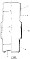
- the shaped box of the drink box type, includes a bottom 1 and a peripheral skirt 2 made integrally with said background 1.
- the form box may include several expanded zones separated by intermediate zones each having a diameter less than diameter of the expanded zones.
- the external profile of the expanded 2B zone can be flat as shown in fig. 1 or curved as shown in Fig. 2.
- we form the expanded area by performing a overall expansion over the entire height of the area to be expanded, for example by a forming process with air or nitrogen under pressure or by a process of forming using an incompressible fluid or by a mechanical expansion process using a tool sectors.
- Shaped boxes have been prepared for from this steel, on the one hand, by stamping-re-stamping of a metal blank to form cylindrical blanks consisting of a bottom and a skirt device of diameter D equal to 84mm, material with said bottom and, on the other hand, by stamping-ironing a metal blank to form drafts cylindrical with diameter D equal to 66mm, corresponding to usual drink cans.
- zone 2B After formation of zone 2B by expansion overall, we see that the maximum diameter it is possible to get is equal to 86.1mm. If we increase still the diameter of the box in the expanded area, we witness a tear in the metal of the skirt wall peripheral.
- the thickness of the wall of the peripheral skirt in the center of the expanded zone 2B of diameter equal to 86.1mm is equal to 0.12mm.
- zone 2B After formation of zone 2B by expansion overall, we see that the maximum diameter it is possible to get is equal to 66.3mm, or a rate maximum expansion equal to 0.4%.
- the thickness of the wall at center of the expanded 2B area is 0.135mm.
- the method according to the invention makes it possible to realize on this type of shaped box, at least one area expanded whose expansion rate is increased so significant.
- the manufacturing process according to the invention consists in making the expanded zone 2B by carrying out minus a step of expanding locally and successively elementary zones 10a, 10b, 10c ... 10n, of the peripheral skirt 2 starting with a first elementary zone 10a located closest to the bottom 1 up to the last elementary area 10n most distant from said bottom.
- the elementary zones 10a, 10b, 10c ... 10n are partially overlap to obtain zone 2B expanded.
- the formation of the zones 10a, 10b, 10c ... 10n is made in several stages i.e. in several passes successive so as to obtain, as shown in the Figures 1 and 2, a first diameter D'1 smaller than diameter D1 and so on until the diameter is obtained final D1 of the expanded zone 2B.
- peripheral skirt 2 has at least two expanded zones, we first form the expanded area as shown above most near bottom 1, then the most distant expanded area said bottom 1.
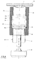
- the formation of the elementary zones 10a, 10B, 10c ... 10n is carried out using a tool 20 which comprises at its periphery an expansion rod 21 of corresponding shape to said elementary zones 10a, 10b, 10c ... 10n.
- the diameter of the expansion rod 21 is less than or equal to 4% of the initial diameter D of the skirt device 2.
- each elementary zone 10a, 10b, 10c ... 10n is greater or equal to 2/3 of the height h of the expansion rod 21, that is to say that the advancement step of the expansion ring 21 to form each elementary zone 10a, 10b, 10c ... 10n is less than or equal to a third of the height h of said expansion ring 21.
- each area elementary 10a, 10b, 10c ... 10n is less than or equal to 1/6 of the height h of the expansion rod 21.
- the expansion ring 21 may have a section in the shape of a spherical cap, a circular section, a rectangular section or a triangular section, this section being a function of the profile of the area 2B expanded to obtain.
- the material constituting the expansion ring 21 is an elastomer.
- Tool 20 can be formed by sectors juxtaposed and radially movable to form, by through the expansion ring 21, the elementary zones 10a, 10b, 10c ... 10n and the vertical displacement not step of this tool 20 can be controlled for example by a jack 22 (Fig. 4).
- the displacements of the tool 20, that is to say expansion and advance step by step, can be controlled by a judicious programming allowing to realize a zone 2B expanded according to the desired profile.
- a counterform 25 is placed around the peripheral skirt 2.
- This counter-form 25 is for example made of elastomer and in this case it is applied directly to the outside of the skirt peripheral 2 or metal and in this case it spares with the outer face of the peripheral skirt a space free to allow the expansion of zone 2B.
- the thickness of the wall of the peripheral skirt 2 in the center of zone 2B expanded east equal to 0.12mm.
- the thickness of the wall of the peripheral skirt 2 in the center of the expanded 2B zone is equal to 0.14mm, 0.02mm more than if the expansion was performed globally over the entire height of the zone 2B to be expanded.
- the thickness of the wall of the peripheral skirt 2 in the center of zone 2B expanded east equal to 0.136mm and the height of the box has decreased by 2mm from the height of the blank, which shows although there was a metal contribution from the part from the peripheral skirt on the side of its free edge towards the area undergoing expansion.
- the manufacturing process for shaped boxes according to the invention therefore allows for boxes of shape with more marked curves and obtained from a metal blank made of steel, or aluminum or aluminum alloy.
Landscapes
- Engineering & Computer Science (AREA)
- Mechanical Engineering (AREA)
- Shaping Metal By Deep-Drawing, Or The Like (AREA)
- Forging (AREA)
- Table Devices Or Equipment (AREA)
- Containers Having Bodies Formed In One Piece (AREA)
Claims (11)
- Verfahren zur Herstellung eines Metallbehälters in einer Form, die einerseits einen Boden (1) und einen umlaufenden zylindrischen Mantel (2) aus dem Material des Bodens (1) umfaßt und wenigstens eine erweiterte Zone (2B) aufweist und andererseits einen Deckel, der auf den umlaufenden Mantel aufgesetzt ist, dadurch gekennzeichnet, daß die wenigstens eine Zone (2B) hergestellt wird, indem wenigstens ein Schritt verwirklicht wird, der darin besteht, örtlich und nacheinander Teilzonen (10a,10b,10c,...10n) des umlaufenden Mantels (2) auszuweiten, indem in einer ersten Teilzone (10a) begonnen wird, das dem Boden (1) am nächsten liegt, bis hin zu einer letzten Teilzone (10n), die am weitesten vom Boden entfernt ist, welche Teilzonen (10a,10b,10c,...10n) sich teilweise überlappen zur Erzielung der wenigstens einen ausgeweiteten Zone (2B).
- Verfahren nach Anspruch 1, dadurch gekennzeichnet, daß an dem umlaufenden Mantel (2) wenigstens zwei ausgeweitete Zonen hergestellt werden, indem zunächst die ausgeweitete Zone, die den Boden am nächsten liegt, und sodann die ausgeweitete Zone, die am weitesten vom Boden entfernt ist, gebildet wird.
- Verfahren nach den Ansprüchen 1 und 2, dadurch gekennzeichnet, daß jede Teilzone (10a,10b,10c,...10n) hergestellt wird mit Hilfe eines Spreizringes (21), der in seiner Form derjenigen der Teilzone entspricht.
- Verfahren nach Anspruch 3, dadurch gekennzeichnet, daß der Durchmesser des Spreizringes (21) kleiner oder gleich 4 % des Ausgangsdurchmessers des umlaufenden Mantels (2) beträgt.
- Verfahren nach Anspruch 3, dadurch gekennzeichnet, daß die Überlappung der Teilzonen (10a,10b,10c,...10n) größer oder gleich 2/3 der Höhe des Spreizringes (21) beträgt.
- Verfahren nach Anspruch 3, dadurch gekennzeichnet, daß die Tiefe jeder Teilzone (10a,10b,10c,...10n) kleiner oder gleich 1/6 der Höhe des Spreizringes (21) beträgt.
- Verfahren nach einem der Ansprüche 3 bis 6, dadurch gekennzeichnet, daß der Spreizring (21) einen Abschnitt in der Form einer Kugelkalotte aufweist.
- Verfahren nach einem der Ansprüche 3 bis 6, dadurch gekennzeichnet, daß der Spreizring (21) einen kreisförmigen Abschnitt aufweist.
- Verfahren nach einem der Ansprüche 3 bis 6, dadurch gekennzeichnet, daß der Spreizring (21) einen rechtwinklingen Abschnitt aufweist.
- Verfahren nach einem der Ansprüche 3 bis 6, dadurch gekennzeichnet, daß der Spreizring (21) einen dreieckigen Abschnitt aufweist.
- Verfahren nach einem der Ansprüche 3 bis 10, dadurch gekennzeichnet, daß der Spreizring (21) aus einem Elastomer besteht.
Applications Claiming Priority (2)
| Application Number | Priority Date | Filing Date | Title |
|---|---|---|---|
| FR9503289A FR2731928B1 (fr) | 1995-03-21 | 1995-03-21 | Procede de fabrication d'une boite metallique de forme |
| FR9503289 | 1995-03-21 |
Publications (2)
| Publication Number | Publication Date |
|---|---|
| EP0733414A1 EP0733414A1 (de) | 1996-09-25 |
| EP0733414B1 true EP0733414B1 (de) | 1999-10-06 |
Family
ID=9477254
Family Applications (1)
| Application Number | Title | Priority Date | Filing Date |
|---|---|---|---|
| EP96400484A Expired - Lifetime EP0733414B1 (de) | 1995-03-21 | 1996-03-07 | Herstellungsverfahren eines Metallbehälters in einer Form |
Country Status (8)
| Country | Link |
|---|---|
| US (1) | US5899105A (de) |
| EP (1) | EP0733414B1 (de) |
| JP (1) | JPH08257659A (de) |
| AT (1) | ATE185295T1 (de) |
| CA (1) | CA2172227A1 (de) |
| DE (1) | DE69604520T2 (de) |
| ES (1) | ES2138298T3 (de) |
| FR (1) | FR2731928B1 (de) |
Families Citing this family (10)
| Publication number | Priority date | Publication date | Assignee | Title |
|---|---|---|---|---|
| GB0029459D0 (en) * | 2000-12-04 | 2001-01-17 | Corus Uk Ltd | Metal container suitable to accommodate a heating or cooling component and method for manufacturing it |
| DE10261534A1 (de) * | 2002-12-23 | 2004-07-15 | Alexander Christ | Spraydose |
| WO2005061149A2 (en) * | 2003-12-22 | 2005-07-07 | Glud & Marstrand A/S | A method and an installation for forming a metal container and a metal container for storing of foodstuff |
| JP4616678B2 (ja) * | 2005-03-25 | 2011-01-19 | 株式会社神戸製鋼所 | 包装容器およびその製造方法 |
| US7726165B2 (en) * | 2006-05-16 | 2010-06-01 | Alcoa Inc. | Manufacturing process to produce a necked container |
| US7934410B2 (en) * | 2006-06-26 | 2011-05-03 | Alcoa Inc. | Expanding die and method of shaping containers |
| MY175342A (en) | 2010-08-20 | 2020-06-19 | Alcoa Inc | Shaped metal container and method for making same |
| US9327338B2 (en) | 2012-12-20 | 2016-05-03 | Alcoa Inc. | Knockout for use while necking a metal container, die system for necking a metal container and method of necking a metal container |
| AU2014317870B2 (en) * | 2013-09-06 | 2018-02-15 | Arconic Technologies Llc | Aluminum alloy products and methods for producing same |
| CN105817512B (zh) * | 2016-05-17 | 2017-10-03 | 安徽中鼎金亚汽车管件制造有限公司 | 一种油冷器金属管加工成型设备 |
Family Cites Families (7)
| Publication number | Priority date | Publication date | Assignee | Title |
|---|---|---|---|---|
| US1645971A (en) * | 1922-08-25 | 1927-10-18 | Clarence H Riegel | Method of making sheet-metal barrels |
| DE749792C (de) * | 1935-09-17 | 1944-12-06 | Verfahren zur Herstellung von ausgebauchten rohrfoermigen Koerpern, z.B. Metallfass-Maenteln | |
| US2194385A (en) * | 1936-09-25 | 1940-03-19 | Barringer Wallis & Manners Ltd | Means for shaping tubes or containers |
| GB1075856A (en) * | 1963-09-18 | 1967-07-12 | Metal Containers Ltd | An apparatus for forming a plurality of axially spaced beads in a hollow, substantially cylindrical sheet metal blank |
| AU7082874A (en) * | 1973-07-06 | 1976-01-08 | Dunlop Ltd | Die presses |
| US4331014A (en) * | 1980-02-29 | 1982-05-25 | Gulf & Western Manufacturing Company | Can beading apparatus |
| FR2634405A1 (fr) * | 1988-07-19 | 1990-01-26 | Carnaud Sa | Procede et dispositif de fabrication d'elements tubulaires cylindriques tels que des corps de fut et elements tubulaires cylindriques obtenus selon ce procede |
-
1995
- 1995-03-21 FR FR9503289A patent/FR2731928B1/fr not_active Expired - Fee Related
-
1996
- 1996-03-07 DE DE69604520T patent/DE69604520T2/de not_active Expired - Fee Related
- 1996-03-07 AT AT96400484T patent/ATE185295T1/de not_active IP Right Cessation
- 1996-03-07 EP EP96400484A patent/EP0733414B1/de not_active Expired - Lifetime
- 1996-03-07 ES ES96400484T patent/ES2138298T3/es not_active Expired - Lifetime
- 1996-03-19 JP JP8062874A patent/JPH08257659A/ja active Pending
- 1996-03-20 US US08/618,815 patent/US5899105A/en not_active Expired - Fee Related
- 1996-03-20 CA CA002172227A patent/CA2172227A1/fr not_active Abandoned
Also Published As
| Publication number | Publication date |
|---|---|
| JPH08257659A (ja) | 1996-10-08 |
| FR2731928A1 (fr) | 1996-09-27 |
| FR2731928B1 (fr) | 1997-06-13 |
| EP0733414A1 (de) | 1996-09-25 |
| ATE185295T1 (de) | 1999-10-15 |
| DE69604520D1 (de) | 1999-11-11 |
| CA2172227A1 (fr) | 1996-09-22 |
| ES2138298T3 (es) | 2000-01-01 |
| DE69604520T2 (de) | 2000-01-20 |
| US5899105A (en) | 1999-05-04 |
Similar Documents
| Publication | Publication Date | Title |
|---|---|---|
| EP0034549B1 (de) | Verfahren zum Einrollen von Rohren in Platten und Werkzeug zur Durchführung dieses Verfahrens | |
| EP0733415B1 (de) | Herstellung eines Metallbehälters in einer Form | |
| EP2839202B1 (de) | Schutzkappe für ein druckflüssigkeitszylinderventil und herstellungsverfahren dafür | |
| EP0733414A1 (de) | Herstellungsverfahren eines Metallbehälters in einer Form | |
| FR2512941A1 (fr) | Echangeur de chaleur a faisceau de tubes paralleles et procede d'assemblage de ses elements constitutifs | |
| EP1045165B1 (de) | Stossabsorbierendes Organ und Herstellungsmethode dafür | |
| EP0852974B1 (de) | Verfahren zum Herstellen von einem metallischen Formbehälter und nach diesem Verfahren hergestellte Getränkedose | |
| FR2499884A1 (fr) | Recipient fabrique par emboutissage | |
| FR2676535A1 (fr) | Echangeur de chaleur muni d'une boite a fluide tubulaire a cloisons transversales, et procede pour sa realisation. | |
| FR2541409A1 (fr) | Poulies a gorges trapezoidales multiples faites de tole et leur procede de fabrication | |
| FR2731927A1 (fr) | Procede de fabrication d'une boite metallique de forme | |
| US3757413A (en) | Method of manufacturing sealing rings | |
| FR3061863A1 (fr) | Dispositif d’emboutissage par magneto-formage et procede associe | |
| EP0839593B1 (de) | Verfahren zum Herstellen eines Hohlrevolutionskörpers durch Fliessdrehen | |
| FR2655576A1 (fr) | Procede et dispositif d'emboutissage de recipients de forme tronconique, et repipient ainsi embouti. | |
| EP1167076A1 (de) | Radscheibe, leicht und mit viel Raum für Bremse | |
| EP0852973B1 (de) | Verfahren zum Herstellen von einem metallischen Formbehälter und durch das Verfahren hergestellter Nahrungsmittelbehälter | |
| FR2730942A1 (fr) | Procede d'elaboration d'une tole ou d'une bande en acier pour la realisation d'une boite et tole ou bande en acier obtenue par ce procede | |
| FR2499882A1 (fr) | Outil pour la formation de recipients emboutis | |
| FR3020289A1 (fr) | Procede d'assemblage d'un ensemble comprenant un tube a une plaque et ensemble ainsi assemble | |
| FR2739581A1 (fr) | Procede de fabrication d'une boite metallique du type boite boisson | |
| EP3969380B1 (de) | Leichte getränkedose aus aluminiumlegierung | |
| WO2014135772A1 (fr) | Outil pour former une collerette a une extremite d'un tube | |
| FR3139740A1 (fr) | Procédé de fabrication d’un dôme sans soudure de grandes dimensions, et dôme correspondant | |
| FR2705256A1 (fr) | Récipient métallique du type boîte de conserve, boîte à ouverture facile ou boîte boisson et procédé de fabrication d'un tel récipient. |
Legal Events
| Date | Code | Title | Description |
|---|---|---|---|
| PUAI | Public reference made under article 153(3) epc to a published international application that has entered the european phase |
Free format text: ORIGINAL CODE: 0009012 |
|
| 17P | Request for examination filed |
Effective date: 19960719 |
|
| AK | Designated contracting states |
Kind code of ref document: A1 Designated state(s): AT BE CH DE DK ES FI FR GB GR IT LI LU NL PT SE |
|
| GRAG | Despatch of communication of intention to grant |
Free format text: ORIGINAL CODE: EPIDOS AGRA |
|
| GRAG | Despatch of communication of intention to grant |
Free format text: ORIGINAL CODE: EPIDOS AGRA |
|
| GRAH | Despatch of communication of intention to grant a patent |
Free format text: ORIGINAL CODE: EPIDOS IGRA |
|
| 17Q | First examination report despatched |
Effective date: 19990315 |
|
| GRAH | Despatch of communication of intention to grant a patent |
Free format text: ORIGINAL CODE: EPIDOS IGRA |
|
| GRAA | (expected) grant |
Free format text: ORIGINAL CODE: 0009210 |
|
| AK | Designated contracting states |
Kind code of ref document: B1 Designated state(s): AT BE CH DE DK ES FI FR GB GR IT LI LU NL PT SE |
|
| PG25 | Lapsed in a contracting state [announced via postgrant information from national office to epo] |
Ref country code: SE Free format text: THE PATENT HAS BEEN ANNULLED BY A DECISION OF A NATIONAL AUTHORITY Effective date: 19991006 Ref country code: GR Free format text: LAPSE BECAUSE OF NON-PAYMENT OF DUE FEES Effective date: 19991006 Ref country code: FI Free format text: LAPSE BECAUSE OF NON-PAYMENT OF DUE FEES Effective date: 19991006 |
|
| REF | Corresponds to: |
Ref document number: 185295 Country of ref document: AT Date of ref document: 19991015 Kind code of ref document: T |
|
| ITF | It: translation for a ep patent filed | ||
| REG | Reference to a national code |
Ref country code: CH Ref legal event code: EP |
|
| GBT | Gb: translation of ep patent filed (gb section 77(6)(a)/1977) |
Effective date: 19991006 |
|
| REF | Corresponds to: |
Ref document number: 69604520 Country of ref document: DE Date of ref document: 19991111 |
|
| REG | Reference to a national code |
Ref country code: ES Ref legal event code: FG2A Ref document number: 2138298 Country of ref document: ES Kind code of ref document: T3 |
|
| PG25 | Lapsed in a contracting state [announced via postgrant information from national office to epo] |
Ref country code: PT Free format text: LAPSE BECAUSE OF FAILURE TO SUBMIT A TRANSLATION OF THE DESCRIPTION OR TO PAY THE FEE WITHIN THE PRESCRIBED TIME-LIMIT Effective date: 20000106 Ref country code: DK Free format text: LAPSE BECAUSE OF FAILURE TO SUBMIT A TRANSLATION OF THE DESCRIPTION OR TO PAY THE FEE WITHIN THE PRESCRIBED TIME-LIMIT Effective date: 20000106 |
|
| PLBE | No opposition filed within time limit |
Free format text: ORIGINAL CODE: 0009261 |
|
| STAA | Information on the status of an ep patent application or granted ep patent |
Free format text: STATUS: NO OPPOSITION FILED WITHIN TIME LIMIT |
|
| 26N | No opposition filed | ||
| REG | Reference to a national code |
Ref country code: GB Ref legal event code: IF02 |
|
| PGFP | Annual fee paid to national office [announced via postgrant information from national office to epo] |
Ref country code: NL Payment date: 20020218 Year of fee payment: 8 |
|
| PGFP | Annual fee paid to national office [announced via postgrant information from national office to epo] |
Ref country code: LU Payment date: 20030217 Year of fee payment: 8 |
|
| PGFP | Annual fee paid to national office [announced via postgrant information from national office to epo] |
Ref country code: CH Payment date: 20030218 Year of fee payment: 8 Ref country code: AT Payment date: 20030218 Year of fee payment: 8 |
|
| PGFP | Annual fee paid to national office [announced via postgrant information from national office to epo] |
Ref country code: GB Payment date: 20030228 Year of fee payment: 8 |
|
| PGFP | Annual fee paid to national office [announced via postgrant information from national office to epo] |
Ref country code: DE Payment date: 20030312 Year of fee payment: 8 |
|
| PGFP | Annual fee paid to national office [announced via postgrant information from national office to epo] |
Ref country code: FR Payment date: 20030313 Year of fee payment: 8 |
|
| PGFP | Annual fee paid to national office [announced via postgrant information from national office to epo] |
Ref country code: ES Payment date: 20030314 Year of fee payment: 8 |
|
| PGFP | Annual fee paid to national office [announced via postgrant information from national office to epo] |
Ref country code: BE Payment date: 20030328 Year of fee payment: 8 |
|
| PG25 | Lapsed in a contracting state [announced via postgrant information from national office to epo] |
Ref country code: LU Free format text: LAPSE BECAUSE OF NON-PAYMENT OF DUE FEES Effective date: 20040307 Ref country code: GB Free format text: LAPSE BECAUSE OF NON-PAYMENT OF DUE FEES Effective date: 20040307 Ref country code: AT Free format text: LAPSE BECAUSE OF NON-PAYMENT OF DUE FEES Effective date: 20040307 |
|
| PG25 | Lapsed in a contracting state [announced via postgrant information from national office to epo] |
Ref country code: ES Free format text: LAPSE BECAUSE OF NON-PAYMENT OF DUE FEES Effective date: 20040308 |
|
| PG25 | Lapsed in a contracting state [announced via postgrant information from national office to epo] |
Ref country code: LI Free format text: LAPSE BECAUSE OF NON-PAYMENT OF DUE FEES Effective date: 20040331 Ref country code: CH Free format text: LAPSE BECAUSE OF NON-PAYMENT OF DUE FEES Effective date: 20040331 Ref country code: BE Free format text: LAPSE BECAUSE OF NON-PAYMENT OF DUE FEES Effective date: 20040331 |
|
| BERE | Be: lapsed |
Owner name: S.A. *SOLLAC Effective date: 20040331 |
|
| PG25 | Lapsed in a contracting state [announced via postgrant information from national office to epo] |
Ref country code: NL Free format text: LAPSE BECAUSE OF NON-PAYMENT OF DUE FEES Effective date: 20041001 Ref country code: DE Free format text: LAPSE BECAUSE OF NON-PAYMENT OF DUE FEES Effective date: 20041001 |
|
| GBPC | Gb: european patent ceased through non-payment of renewal fee | ||
| REG | Reference to a national code |
Ref country code: CH Ref legal event code: PL |
|
| PG25 | Lapsed in a contracting state [announced via postgrant information from national office to epo] |
Ref country code: FR Free format text: LAPSE BECAUSE OF NON-PAYMENT OF DUE FEES Effective date: 20041130 |
|
| NLV4 | Nl: lapsed or anulled due to non-payment of the annual fee |
Effective date: 20041001 |
|
| REG | Reference to a national code |
Ref country code: FR Ref legal event code: ST |
|
| PG25 | Lapsed in a contracting state [announced via postgrant information from national office to epo] |
Ref country code: IT Free format text: LAPSE BECAUSE OF NON-PAYMENT OF DUE FEES;WARNING: LAPSES OF ITALIAN PATENTS WITH EFFECTIVE DATE BEFORE 2007 MAY HAVE OCCURRED AT ANY TIME BEFORE 2007. THE CORRECT EFFECTIVE DATE MAY BE DIFFERENT FROM THE ONE RECORDED. Effective date: 20050307 |
|
| REG | Reference to a national code |
Ref country code: ES Ref legal event code: FD2A Effective date: 20040308 |