EP0733416A1 - Procédé et dispositif de fabrication de treillis d'armature - Google Patents
Procédé et dispositif de fabrication de treillis d'armature Download PDFInfo
- Publication number
- EP0733416A1 EP0733416A1 EP96890033A EP96890033A EP0733416A1 EP 0733416 A1 EP0733416 A1 EP 0733416A1 EP 96890033 A EP96890033 A EP 96890033A EP 96890033 A EP96890033 A EP 96890033A EP 0733416 A1 EP0733416 A1 EP 0733416A1
- Authority
- EP
- European Patent Office
- Prior art keywords
- longitudinal
- welding machine
- bars
- feed
- crossbar
- Prior art date
- Legal status (The legal status is an assumption and is not a legal conclusion. Google has not performed a legal analysis and makes no representation as to the accuracy of the status listed.)
- Granted
Links
Images


Classifications
-
- B—PERFORMING OPERATIONS; TRANSPORTING
- B21—MECHANICAL METAL-WORKING WITHOUT ESSENTIALLY REMOVING MATERIAL; PUNCHING METAL
- B21F—WORKING OR PROCESSING OF METAL WIRE
- B21F27/00—Making wire network, i.e. wire nets
- B21F27/08—Making wire network, i.e. wire nets with additional connecting elements or material at crossings
- B21F27/10—Making wire network, i.e. wire nets with additional connecting elements or material at crossings with soldered or welded crossings
-
- B—PERFORMING OPERATIONS; TRANSPORTING
- B21—MECHANICAL METAL-WORKING WITHOUT ESSENTIALLY REMOVING MATERIAL; PUNCHING METAL
- B21F—WORKING OR PROCESSING OF METAL WIRE
- B21F27/00—Making wire network, i.e. wire nets
- B21F27/12—Making special types or portions of network by methods or means specially adapted therefor
-
- B—PERFORMING OPERATIONS; TRANSPORTING
- B21—MECHANICAL METAL-WORKING WITHOUT ESSENTIALLY REMOVING MATERIAL; PUNCHING METAL
- B21F—WORKING OR PROCESSING OF METAL WIRE
- B21F27/00—Making wire network, i.e. wire nets
- B21F27/12—Making special types or portions of network by methods or means specially adapted therefor
- B21F27/20—Making special types or portions of network by methods or means specially adapted therefor of plaster-carrying network
Definitions
- the invention relates to a method for producing reinforcement meshes, which consist of longitudinal and cross bars welded to one another, after which the longitudinal bars, which are aligned and cut in a preparation step, are placed on a feed device and in the longitudinal direction in the mat-appropriate position, taking into account any mesh recesses or the like guided step by step from crossbar position to crossbar position by a welding machine and in each case welded to the crossbars belonging to these crossbar positions, also directed in a preparatory step, cut and positioned to suit the mat, taking into account any mat recesses or the like, and to a device for carrying out this method.
- the invention is therefore based on the object of eliminating these deficiencies and of specifying a method of the type described at the outset which permits relatively quick and rational mat production.
- a space-saving and low-cost device for carrying out this method is to be created.
- the invention solves this problem by first placing only the longitudinal bars reaching the foremost crossbar position (s) in the feed direction and then the rest of the series, as they reach the successive crossbar positions with their front ends.
- the longitudinal and cross bars can consist of different diameters and in the course of the mat production in a preparation step from corresponding wire reels, be straightened and cut, the rods also with spacers u.
- the like. Can be equipped. The individual process steps, the positioning and alignment of the bars, the choice of materials and the like. The like. Can be carried out automatically by means of suitable control programs, so that any individually designed mats or different standard mats can be produced one after the other without interruption. Due to the possibility of an immediately successive manufacture of the individual reinforcement meshes, the space requirements for the manufacture remain within manageable limits and the feed device does not have to be designed in the feed direction in front of the welding machine to be at least two full mesh lengths as in the known systems.
- a particularly useful device for carrying out the method according to the invention has a feed device assigned to a welding machine, a longitudinal bar magazine and a cross bar magazine and laying devices for the longitudinal and transverse bars and is characterized in that the feed device in front of the welding machine also has a feed carriage which can be moved back and forth in the feed direction a plurality of side-by-side mounting profiles for inserting the longitudinal rods and behind the welding machine includes a towing carriage movable in the pull-off direction with tongs laterally offset from the mounting profiles.
- the longitudinal bars are inserted into the receiving profiles of the feed carriage in a mat-appropriate manner and brought into the welding machine by advancing the feed carriage.
- the tongs of the tow truck approached to the welding machine can grip the welded crossbars and the longitudinal bars held together by the crossbars can be pulled forward with the tow truck and welded to the crossbars one after the other.
- the feed carriage stands still and the longitudinal bars are pulled out of the receiving profiles.
- the front ends of the longitudinal bars can be pressed against the raised straightening swords and aligned with them in a simple manner. After aligning and lowering the sabers, the feed carriage brings the longitudinal bars with their front ends aligned into the welding machine.
- the feed carriages are moved back relative to these longitudinal bars, the new longitudinal bars are placed in the correct position, the feed carriage moves the new longitudinal bars relative to the clamped longitudinal rods against the again raised swords, so that the new longitudinal rods are also aligned, and after completion of the respective welding step, the feed carriage with the new longitudinal rods is fed together with the other longitudinal rods to the welding machine during the next feed step, where then the welded-on crossbars
- the new longitudinal bars are connected to the already installed longitudinal bars. It is of course also possible to arrange the longitudinal bars with different overhangs with respect to the foremost cross bar and then to adjust them step by step.
- the welding machine is assigned a crossbar magazine bridging the feed device, which has a plurality of receiving compartments for the positioned receiving of crossbars, wherein a straightening device can preferably be assigned to the receiving compartments.
- a cross bar magazine which is designed as a flap magazine or chain magazine or the like
- the cross bars are already brought into the position of the welding machine in a position suitable for the mat and can be welded onto the longitudinal bars in a rational manner.
- a straightening device for example a straightening magnet, allows the positioned transverse support to be checked within the receiving compartments, so that perfect mat production is ensured.
- the cross bars which optionally belong to one another along a common cross bar position, are also placed together on the longitudinal bars and welded to them, the respective crossbar position depends on the longitudinal bar feed and can therefore be selected as required.
- the mechanical outlay can be significantly reduced and a very flexible welding device can be achieved.
- the individual welding heads are positioned transversely as required, so that separate welding units are no longer required for all mounting profiles of the feed carriage.
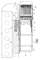
- a device 1 for the automatic production of reinforcement meshes M comprises a straightening and cutting machine 2 for the preparatory processing of reinforcement wires into longitudinal and transverse bars, a transverse rod magazine 3 and a longitudinal rod magazine 4 and a welding machine 5 with a suitable feed device 6.
- the straightening and cutting machine 2 is equipped with a plurality of wire reels 21 for the different wire diameters and, with straightening and cutting devices (not shown further), allows the selected wires to be aligned and cut, which are then distributed via a distributor 22 as longitudinal bars L into the longitudinal bar magazine 4 or as transverse bars Q are placed in the cross bar magazine 3, where they are waiting for further processing.
- the longitudinal rod magazine 4 extends parallel to the feed device 6 and is a laying robot 41 assigned.
- the cross bar magazine 3 is divided into a longitudinal buffer store 31 and a cross-directional flap magazine 32 bridging the feed device 6, the flap magazine 32 having a plurality of receiving compartments 33 arranged in series, which, depending on the progress of work, from the buffer store 31 via a suitable laying device 34 with the prepared cross bars in the correct position become.
- the welding machine 5 has individual transverse adjustable welding heads 51 for welding the longitudinal and transverse bars, the welding heads being positioned according to the welding points.
- the feed device 6 is composed of a feed carriage 61, which can be moved back and forth in the feed direction in front of the welding machine 5 on a suitable frame 62 and has a multiplicity of receiving profiles 63 arranged next to one another for inserting the longitudinal bars L, and also of a towing carriage 64 arranged downstream of the welding machine 5 compared to the receiving profiles 63 laterally offset tongs 65, which can be moved in the pull-off direction and can penetrate with its tongs 65 into the area of the welding machine 5.
- a straightening station 7 with elevating swords 71 is provided for longitudinally aligning the longitudinal bars L placed on the feed carriage 61, and a displacement device 72 for positioning the crossbar is also assigned to the flap magazine 32 of the crossbar magazine 3.
- the required transverse and longitudinal bars are prepared in preparation steps in the wire straightening and cutting machine 2 and the Longitudinal or cross bar magazines 3, 4 fed.
- the cross bars Q are lined up in the flap magazine 32 in the order in which they are processed in a position and size that is appropriate for the mat, the excess cross bars Q not finding space in the flap magazine initially remaining in the buffer store 31.
- the longitudinal bars L are removed from the longitudinal bar magazine 4 via the laying robot 41 and inserted into the receiving profiles 63 of the feed carriage 61 in a manner suitable for the mat, only the longitudinal bars which protrude into or to a foremost transverse bar position being inserted first.
- the feed carriage 61 is in its retracted initial position and receives the longitudinal bars with a suitable overhang relative to the receiving profiles 63. Now the feed carriage 61 is advanced by means of its feed drive 66 against the straightening station 7 with its raised swords 71 so that the longitudinal bars pressed against the swords 71 are positioned exactly. After positioning, the guide blades 71 are lowered and the feed carriage 61 introduces the longitudinal bars into the welding machine 5 by further advancing.
- the longitudinal bars are now welded via the appropriately positioned welding heads 51 to the cross bar or bars assigned to the first cross bar position, which are located in the first folding compartment of the folding magazine 32 and are fed to the welding machine 5 by opening this compartment. If the first foldable compartment is empty, the subsequent transverse rods are gradually conveyed by folding over the following foldable compartments 33 and prepared for the welding process.
- the towing vehicle 64 is advanced and the tongs 65 are suspended in the welded crossbar, which is possible without difficulty due to the offset of the tongs relative to the receiving profiles.
- the longitudinal bars can be pulled off the feed wagon 61 and released until the next one selectable and variable crossbar position are introduced into the welding machine 5.
- the towing vehicle 64 stops, the next cross bar or bars are transferred to the welding machine 5 and welded on.
- the corresponding cross bars are now welded onto the longitudinal bars step by step.
- the feed carriage 61 moves back to its starting position relative to the longitudinal bars clamped by the tongs 65, so that, similar to the first longitudinal bars, an ancestor against the straightening station 7 then also enables the new longitudinal bars to be aligned and then the longitudinal rods are properly retracted into the welding machine.
- a connection between the already welded rods and the new longitudinal rods is then made here with the next transverse rod, so that the new longitudinal rods are also pulled along via the towing vehicle 64.
- the required longitudinal bars L and cross bars Q are first prepared and stored (Fig. 3a), then Longitudinal bars La placed on the feed device 6, which reach the first crossbar position P1 with their front ends (Fig. 3b), so that after the welding of the first crossbar Qa by means of the welding machine 5, the further mat feed can take place via the tongs.
- the various cross bars Q which are cut and positioned according to the shape of the mat, are welded on until position P2 is reached in the welding machine, whereupon new, shorter longitudinal bars Lb are inserted.
- the longitudinal bars Lb are placed and aligned so that in the next feed step all the longitudinal bars La, Lb reaching the position P3 enter the welding machine (FIG. 3c).
- the cross bar Qc is welded on and thus all existing longitudinal bars La, Lb are connected to each other, which means that a further advance is again only possible using the tongs.
- the remaining cross bars Q are finally welded on step by step until the mat M is finished (FIG. 3d).
Landscapes
- Engineering & Computer Science (AREA)
- Mechanical Engineering (AREA)
- Wire Processing (AREA)
- Manufacturing Of Tubular Articles Or Embedded Moulded Articles (AREA)
- Reinforcement Elements For Buildings (AREA)
Applications Claiming Priority (2)
| Application Number | Priority Date | Filing Date | Title |
|---|---|---|---|
| AT52895 | 1995-03-24 | ||
| AT528/95 | 1995-03-24 |
Publications (2)
| Publication Number | Publication Date |
|---|---|
| EP0733416A1 true EP0733416A1 (fr) | 1996-09-25 |
| EP0733416B1 EP0733416B1 (fr) | 1999-05-19 |
Family
ID=3493015
Family Applications (1)
| Application Number | Title | Priority Date | Filing Date |
|---|---|---|---|
| EP96890033A Expired - Lifetime EP0733416B1 (fr) | 1995-03-24 | 1996-03-05 | Procédé et dispositif de fabrication de treillis d'armature |
Country Status (4)
| Country | Link |
|---|---|
| EP (1) | EP0733416B1 (fr) |
| JP (1) | JPH091270A (fr) |
| AT (1) | ATE180186T1 (fr) |
| DE (1) | DE59601916D1 (fr) |
Cited By (7)
| Publication number | Priority date | Publication date | Assignee | Title |
|---|---|---|---|---|
| EP1145783A3 (fr) * | 2000-04-14 | 2002-07-24 | Progress Maschinen & Automation AG | Procédé pour la fabrication de cages d'armature en acier |
| WO2011114175A1 (fr) * | 2010-03-15 | 2011-09-22 | Anagnostopoulos Antonios | Procédé et machine pour produire une armature quadrillée à partir de barres d'armature, de fils de fer ou d'un autre matériau à section prismatique par un apport de métal par soudure |
| WO2011158070A1 (fr) * | 2010-06-18 | 2011-12-22 | A.W.M. S.P.A. | Procédé consistant à approvisionner des installations pour la formation automatique de treillis métalliques soudés à l'arc présentant des formes profilées spéciales en barres ou tiges entières en acier dans la direction longitudinale et appareil associé pour lesdites productions |
| EP2433724A1 (fr) * | 2010-09-27 | 2012-03-28 | A.W.M. s.p.a. | Système d'alimentation et dispositif d'alimentation transversal correspondant pour des barres entières ou des barres d'acier adaptées pour des installations automatiques produisant un filet de fils de soudage avec des formes particulières |
| US10926315B2 (en) | 2014-04-01 | 2021-02-23 | Antonios Anagnostopoulos | Systems and processes for feeding longitudinal wires or rods to mesh producing machines |
| WO2021209304A1 (fr) * | 2020-04-15 | 2021-10-21 | Progress Maschinen & Automation Ag | Système de soudage de plaques pour la production de plaques de béton armé et procédé utilisant celui-ci |
| US11389857B2 (en) * | 2017-06-06 | 2022-07-19 | M.E.P. Macchine Elettroniche Piegatrici S.P.A. | Apparatus and method to make a wire mesh |
Families Citing this family (3)
| Publication number | Priority date | Publication date | Assignee | Title |
|---|---|---|---|---|
| TW419925B (en) | 1998-01-27 | 2001-01-21 | Mitsubishi Electric Corp | Method and apparatus for arithmetic operation and recording medium thereof |
| AT407718B (de) * | 1999-10-22 | 2001-05-25 | Filzmoser Franz | Vorrichtung zum verarbeiten von bewehrungsdrähten zu wenigstens zwei gruppen unterschiedlich langer stäbe für eine bewehrung, insbesondere eine bewehrungsmatte |
| EP3715009B1 (fr) * | 2019-03-28 | 2025-10-08 | apilion machines + services GmbH | Procédé de fabrication de grillage formant armature |
Citations (4)
| Publication number | Priority date | Publication date | Assignee | Title |
|---|---|---|---|---|
| FR2408407A1 (fr) * | 1977-10-24 | 1979-06-08 | Trefilunion | Procede et dispositif pour la fabrication d'une armature en treillis metallique plan soude, et armature en resultant |
| EP0482842A1 (fr) * | 1990-10-25 | 1992-04-29 | Partek Concrete Engineering Oy Ab | Procédé et dispositif pour la fabrication automatique de renforcements en acier pour des éléments en béton |
| WO1995006532A1 (fr) * | 1993-08-30 | 1995-03-09 | Claudio Bernardinis | Dispositif automatique d'alimentation en barres |
| EP0677343A1 (fr) * | 1994-04-13 | 1995-10-18 | Wilhelm Häussler | Procédé et appareil pour la production de châssis de coffrage |
-
1996
- 1996-03-05 AT AT96890033T patent/ATE180186T1/de not_active IP Right Cessation
- 1996-03-05 EP EP96890033A patent/EP0733416B1/fr not_active Expired - Lifetime
- 1996-03-05 DE DE59601916T patent/DE59601916D1/de not_active Expired - Fee Related
- 1996-03-25 JP JP8068727A patent/JPH091270A/ja active Pending
Patent Citations (4)
| Publication number | Priority date | Publication date | Assignee | Title |
|---|---|---|---|---|
| FR2408407A1 (fr) * | 1977-10-24 | 1979-06-08 | Trefilunion | Procede et dispositif pour la fabrication d'une armature en treillis metallique plan soude, et armature en resultant |
| EP0482842A1 (fr) * | 1990-10-25 | 1992-04-29 | Partek Concrete Engineering Oy Ab | Procédé et dispositif pour la fabrication automatique de renforcements en acier pour des éléments en béton |
| WO1995006532A1 (fr) * | 1993-08-30 | 1995-03-09 | Claudio Bernardinis | Dispositif automatique d'alimentation en barres |
| EP0677343A1 (fr) * | 1994-04-13 | 1995-10-18 | Wilhelm Häussler | Procédé et appareil pour la production de châssis de coffrage |
Cited By (10)
| Publication number | Priority date | Publication date | Assignee | Title |
|---|---|---|---|---|
| EP1145783A3 (fr) * | 2000-04-14 | 2002-07-24 | Progress Maschinen & Automation AG | Procédé pour la fabrication de cages d'armature en acier |
| WO2011114175A1 (fr) * | 2010-03-15 | 2011-09-22 | Anagnostopoulos Antonios | Procédé et machine pour produire une armature quadrillée à partir de barres d'armature, de fils de fer ou d'un autre matériau à section prismatique par un apport de métal par soudure |
| WO2011158070A1 (fr) * | 2010-06-18 | 2011-12-22 | A.W.M. S.P.A. | Procédé consistant à approvisionner des installations pour la formation automatique de treillis métalliques soudés à l'arc présentant des formes profilées spéciales en barres ou tiges entières en acier dans la direction longitudinale et appareil associé pour lesdites productions |
| EP2433724A1 (fr) * | 2010-09-27 | 2012-03-28 | A.W.M. s.p.a. | Système d'alimentation et dispositif d'alimentation transversal correspondant pour des barres entières ou des barres d'acier adaptées pour des installations automatiques produisant un filet de fils de soudage avec des formes particulières |
| ITUD20100173A1 (it) * | 2010-09-27 | 2012-03-28 | Awm Spa | "metodo di alimentazione e relativo alimentatore trasversale di barre intere o tondini d'acciaio per impianti di formazione automatica di reti metalliche elettrosaldate aventi forme sagomate speciali". |
| US10926315B2 (en) | 2014-04-01 | 2021-02-23 | Antonios Anagnostopoulos | Systems and processes for feeding longitudinal wires or rods to mesh producing machines |
| US11389857B2 (en) * | 2017-06-06 | 2022-07-19 | M.E.P. Macchine Elettroniche Piegatrici S.P.A. | Apparatus and method to make a wire mesh |
| WO2021209304A1 (fr) * | 2020-04-15 | 2021-10-21 | Progress Maschinen & Automation Ag | Système de soudage de plaques pour la production de plaques de béton armé et procédé utilisant celui-ci |
| EP4135916B1 (fr) * | 2020-04-15 | 2024-11-13 | Progress Maschinen & Automation AG | Système de soudage de plaques pour la production de plaques de béton armé et procédé utilisant celui-ci |
| EP4480598A3 (fr) * | 2020-04-15 | 2025-04-02 | Progress Maschinen & Automation AG | Installation de soudage de mats pour la fabrication de treillis en acier et procede d'utilisation de cette installation |
Also Published As
| Publication number | Publication date |
|---|---|
| JPH091270A (ja) | 1997-01-07 |
| DE59601916D1 (de) | 1999-06-24 |
| ATE180186T1 (de) | 1999-06-15 |
| EP0733416B1 (fr) | 1999-05-19 |
Similar Documents
| Publication | Publication Date | Title |
|---|---|---|
| EP0371956B1 (fr) | Procédé et installation pour amener des éléments longitudinaux à une machine de soudage pour la fabrication de treillis ou de caillebottis | |
| EP0069108B1 (fr) | Procédé et dispositif pour fabriquer des corps de matelas soudés | |
| DE3245179A1 (de) | Verfahren und vorrichtung zum herstellen von gitterrosten | |
| EP0482674B1 (fr) | Procédé de fabrication d'un matelas à ressorts comprenant un noyau à ressorts pourvu d'un cadre à sa partie supérieure et inférieure | |
| WO1996003234A1 (fr) | Installation de production continue d'elements de construction | |
| EP0733416B1 (fr) | Procédé et dispositif de fabrication de treillis d'armature | |
| EP4135916B1 (fr) | Système de soudage de plaques pour la production de plaques de béton armé et procédé utilisant celui-ci | |
| DE2051354C3 (de) | Vorrichtung zum Zuführen von Längsdrähten zu Gitterschweißmaschinen | |
| EP0678374A2 (fr) | Procédé et appareil pour la fabrication d'un cadre, en particulier un cadre de fenêtre | |
| EP2414115A1 (fr) | Procédé et installation de production continue de cages d'armature | |
| DE69110432T2 (de) | Herstellung von aus amorphem Metallband bestehenden Paketen. | |
| DE10048104B4 (de) | Vorrichtung zum Verarbeiten von Bewehrungsdrähten zu wenigstens zwei Gruppen unterschiedlich langer Stäbe für eine Bewehrung | |
| AT405030B (de) | Anlage zum herstellen von bewehrungsmatten | |
| DE3249620C2 (de) | Verfahren zum Herstellen von Gitterrosten | |
| WO1990008606A1 (fr) | Dispositif d'alimentation de machines de soudage de grilles en elements longitudinaux | |
| EP0414061A1 (fr) | Dispositif pour retirer une barre métallique d'un faisceau de barres | |
| DE2617696C3 (de) | Verfahren zum Herstellen von Gitterrosten | |
| AT397357B (de) | Vorrichtung zur herstellung von als bewehrung von stahlbetonbauteilen dienenden positionsstabmatten | |
| DE2535480C2 (de) | Verfahren und Vorrichtung zum Aussortieren von Unterlängen und/oder zum Schneiden vorbestimmter Längen aus Stabmaterial unterschiedlicher Längen | |
| DE19648444C1 (de) | Elektronisch gesteuertes, vollautomatisches Verfahren und Vorrichtung zur Herstellung von Positionsstabmatten zur Bewehrung von Stahlbetonbauteilen | |
| EP1426124A1 (fr) | Dispositif d'alimentation en barres longitudinales | |
| EP0868236B1 (fr) | Procede et installation pour la fabrication de mats en treillis | |
| DE2123501C (de) | Verfahren und Vorrichtung zum Herstellen von Drahtgittern aus sich rechtwinklig kreuzenden Langs und Querdrahten | |
| AT207207B (de) | Verfahren und Einrichtung zum Verschweißen von im Raum beliebig angeordneten Trägerteilen mit Verbinderteilen | |
| AT520175B1 (de) | Gittermattenschweißmaschine und Verfahren zum Betreiben einer Gittermattenschweißmaschine |
Legal Events
| Date | Code | Title | Description |
|---|---|---|---|
| PUAI | Public reference made under article 153(3) epc to a published international application that has entered the european phase |
Free format text: ORIGINAL CODE: 0009012 |
|
| AK | Designated contracting states |
Kind code of ref document: A1 Designated state(s): AT CH DE FR GB LI |
|
| 17P | Request for examination filed |
Effective date: 19970307 |
|
| GRAG | Despatch of communication of intention to grant |
Free format text: ORIGINAL CODE: EPIDOS AGRA |
|
| GRAG | Despatch of communication of intention to grant |
Free format text: ORIGINAL CODE: EPIDOS AGRA |
|
| GRAH | Despatch of communication of intention to grant a patent |
Free format text: ORIGINAL CODE: EPIDOS IGRA |
|
| 17Q | First examination report despatched |
Effective date: 19981022 |
|
| GRAH | Despatch of communication of intention to grant a patent |
Free format text: ORIGINAL CODE: EPIDOS IGRA |
|
| GRAA | (expected) grant |
Free format text: ORIGINAL CODE: 0009210 |
|
| AK | Designated contracting states |
Kind code of ref document: B1 Designated state(s): AT CH DE FR GB LI |
|
| REF | Corresponds to: |
Ref document number: 180186 Country of ref document: AT Date of ref document: 19990615 Kind code of ref document: T |
|
| REG | Reference to a national code |
Ref country code: CH Ref legal event code: EP |
|
| GBT | Gb: translation of ep patent filed (gb section 77(6)(a)/1977) |
Effective date: 19990528 |
|
| REF | Corresponds to: |
Ref document number: 59601916 Country of ref document: DE Date of ref document: 19990624 |
|
| ET | Fr: translation filed | ||
| REG | Reference to a national code |
Ref country code: CH Ref legal event code: NV Representative=s name: DIPL.-ING. W. STEUDTNER |
|
| PGFP | Annual fee paid to national office [announced via postgrant information from national office to epo] |
Ref country code: GB Payment date: 20000221 Year of fee payment: 5 |
|
| PLBE | No opposition filed within time limit |
Free format text: ORIGINAL CODE: 0009261 |
|
| STAA | Information on the status of an ep patent application or granted ep patent |
Free format text: STATUS: NO OPPOSITION FILED WITHIN TIME LIMIT |
|
| PG25 | Lapsed in a contracting state [announced via postgrant information from national office to epo] |
Ref country code: LI Free format text: LAPSE BECAUSE OF NON-PAYMENT OF DUE FEES Effective date: 20000331 Ref country code: CH Free format text: LAPSE BECAUSE OF NON-PAYMENT OF DUE FEES Effective date: 20000331 |
|
| 26N | No opposition filed | ||
| REG | Reference to a national code |
Ref country code: CH Ref legal event code: PL |
|
| PG25 | Lapsed in a contracting state [announced via postgrant information from national office to epo] |
Ref country code: GB Free format text: LAPSE BECAUSE OF NON-PAYMENT OF DUE FEES Effective date: 20010305 |
|
| GBPC | Gb: european patent ceased through non-payment of renewal fee |
Effective date: 20010305 |
|
| REG | Reference to a national code |
Ref country code: FR Ref legal event code: TP |
|
| PGFP | Annual fee paid to national office [announced via postgrant information from national office to epo] |
Ref country code: AT Payment date: 20090325 Year of fee payment: 14 |
|
| PGFP | Annual fee paid to national office [announced via postgrant information from national office to epo] |
Ref country code: FR Payment date: 20090331 Year of fee payment: 14 Ref country code: DE Payment date: 20090529 Year of fee payment: 14 |
|
| PG25 | Lapsed in a contracting state [announced via postgrant information from national office to epo] |
Ref country code: AT Free format text: LAPSE BECAUSE OF NON-PAYMENT OF DUE FEES Effective date: 20100305 |
|
| REG | Reference to a national code |
Ref country code: FR Ref legal event code: ST Effective date: 20101130 |
|
| PG25 | Lapsed in a contracting state [announced via postgrant information from national office to epo] |
Ref country code: FR Free format text: LAPSE BECAUSE OF NON-PAYMENT OF DUE FEES Effective date: 20100331 |
|
| PG25 | Lapsed in a contracting state [announced via postgrant information from national office to epo] |
Ref country code: DE Free format text: LAPSE BECAUSE OF NON-PAYMENT OF DUE FEES Effective date: 20101001 |