EP0733443A1 - Dispositif pour transmettre des coups par impulsion sur un outil à rotation continue - Google Patents
Dispositif pour transmettre des coups par impulsion sur un outil à rotation continue Download PDFInfo
- Publication number
- EP0733443A1 EP0733443A1 EP96810017A EP96810017A EP0733443A1 EP 0733443 A1 EP0733443 A1 EP 0733443A1 EP 96810017 A EP96810017 A EP 96810017A EP 96810017 A EP96810017 A EP 96810017A EP 0733443 A1 EP0733443 A1 EP 0733443A1
- Authority
- EP
- European Patent Office
- Prior art keywords
- tool
- housing
- hand
- spring
- adapter
- Prior art date
- Legal status (The legal status is an assumption and is not a legal conclusion. Google has not performed a legal analysis and makes no representation as to the accuracy of the status listed.)
- Granted
Links
Images

Classifications
-
- B—PERFORMING OPERATIONS; TRANSPORTING
- B25—HAND TOOLS; PORTABLE POWER-DRIVEN TOOLS; MANIPULATORS
- B25D—PERCUSSIVE TOOLS
- B25D16/00—Portable percussive machines with superimposed rotation, the rotational movement of the output shaft of a motor being modified to generate axial impacts on the tool bit
-
- B—PERFORMING OPERATIONS; TRANSPORTING
- B25—HAND TOOLS; PORTABLE POWER-DRIVEN TOOLS; MANIPULATORS
- B25D—PERCUSSIVE TOOLS
- B25D17/00—Details of, or accessories for, portable power-driven percussive tools
- B25D17/005—Attachments or adapters placed between tool and hammer
-
- B—PERFORMING OPERATIONS; TRANSPORTING
- B23—MACHINE TOOLS; METAL-WORKING NOT OTHERWISE PROVIDED FOR
- B23B—TURNING; BORING
- B23B2260/00—Details of constructional elements
- B23B2260/128—Sensors
-
- B—PERFORMING OPERATIONS; TRANSPORTING
- B25—HAND TOOLS; PORTABLE POWER-DRIVEN TOOLS; MANIPULATORS
- B25D—PERCUSSIVE TOOLS
- B25D2211/00—Details of portable percussive tools with electromotor or other motor drive
- B25D2211/06—Means for driving the impulse member
- B25D2211/068—Crank-actuated impulse-driving mechanisms
-
- Y—GENERAL TAGGING OF NEW TECHNOLOGICAL DEVELOPMENTS; GENERAL TAGGING OF CROSS-SECTIONAL TECHNOLOGIES SPANNING OVER SEVERAL SECTIONS OF THE IPC; TECHNICAL SUBJECTS COVERED BY FORMER USPC CROSS-REFERENCE ART COLLECTIONS [XRACs] AND DIGESTS
- Y10—TECHNICAL SUBJECTS COVERED BY FORMER USPC
- Y10T—TECHNICAL SUBJECTS COVERED BY FORMER US CLASSIFICATION
- Y10T408/00—Cutting by use of rotating axially moving tool
- Y10T408/23—Cutting by use of rotating axially moving tool including means to cause Tool to progressively vibrate toward work
-
- Y—GENERAL TAGGING OF NEW TECHNOLOGICAL DEVELOPMENTS; GENERAL TAGGING OF CROSS-SECTIONAL TECHNOLOGIES SPANNING OVER SEVERAL SECTIONS OF THE IPC; TECHNICAL SUBJECTS COVERED BY FORMER USPC CROSS-REFERENCE ART COLLECTIONS [XRACs] AND DIGESTS
- Y10—TECHNICAL SUBJECTS COVERED BY FORMER USPC
- Y10T—TECHNICAL SUBJECTS COVERED BY FORMER US CLASSIFICATION
- Y10T74/00—Machine element or mechanism
- Y10T74/18—Mechanical movements
- Y10T74/18024—Rotary to reciprocating and rotary
Definitions
- the invention relates to a device for transmitting pulse-like impacts to a continuously rotating tool according to the preamble of claim 1.
- hammer drills have proven themselves for drilling holes in mineral substrates such as concrete, stone and masonry. Hammer drills have a continuously driven tool holder and a motor-operated hammer mechanism. In operation, a pulse-like impact is transmitted to a continuously rotating tool clamped in the tool holder, which supports the processing of the surface.
- the striking mechanism is an electro-pneumatic striking mechanism which transmits longitudinal impacts to the tool.
- the object of the present invention is therefore to provide a device which allows different substrates to be processed efficiently and safely by hand, preferably in dry use.
- the safety of the user should also be guaranteed in the case of reinforcement hits and dangerous torque peaks should be avoided.
- the device should allow the attachment point to be placed at the desired location even in the case of a reinforcement hit.
- the device should make it possible to continue using existing handheld devices without major modifications.
- the device according to the invention is designed as an adapter which, on the one hand, can be inserted into the tool holder of a hand-held device equipped with a striking mechanism and, on the other hand, has a holder for a tool, and which is equipped within a housing with means which correspond to the pulse-like generated by the striking mechanism of the hand-held device Impact component superimposed on a second impact component such that an impulsive twist impact can be transmitted to the tool, which is composed of a longitudinal impact component and a torsional impact component.
- the direction of the force vector on the cutting edge of the tool acting on the surface to be machined is rotated, for example, relative to a tool with mere longitudinal impact support from the axial direction of the tool. Due to the changed direction of the force vector, the reinforcing steel is broken down by shear in the case of reinforcement hits. As a result, sudden torque peaks when the tool is stuck can be avoided and safety for the user of the handheld device can be increased will. But even on mineral substrates without reinforcement, the shear effect of the drill stroke supports the mining process. Due to the energetically more favorable mining process, the heat development is reduced, which is why additional cooling is not necessary even for larger diameter bores in particularly hard substrates.
- a hand-held device which is equipped, for example, with a striking mechanism for longitudinal strikes
- an adapter according to the invention which superimposes a torsional component on the longitudinal striking component in order to generate an impulsive drilling impact, also allows the efficient removal of brittle and / or ductile-failing substrates in dry use.
- the means for impact transmission arranged within the housing comprise scenes and / or driving surfaces, with the aid of which part of the impact energy of a longitudinal impact generated by the striking mechanism of the hand-held device can be converted to produce the torsional impact component.
- the experience of the known hammer drilling devices with longitudinal impact support can be used.
- the longitudinal impact which is preferably generated by an electropneumatic striking mechanism, is converted into a drilling impact using known physical principles. In particular, the effects of wedge, lever, pressure propagation, elastic shear deformation or also transverse contraction can be used to generate the second impact component.
- the principle of converting part of the impact energy in the adapter also works on the basis of a torsion hammer mechanism.
- the impact energy of the longitudinal impact can be partially converted into a torsional impact component
- the impact energy of a torsional impact can also be partially converted into a longitudinal impact component.
- the means arranged within the housing of the adapter for generating the twist impact also in this case preferably interact with scenes and / or driving surfaces. The impact components generated in this way are in turn superimposed to form a drilling impact, which causes both chiseling and shearing processing of the surface.
- a particularly compact design of the adapter results if the links and / or driving surfaces are arranged on the end of an intermediate striker located within the housing, the other end of which is designed as an interface to the tool holder of the hand-held device, and interact with correspondingly configured counter-links and / or driving surfaces , which are provided at the insertion end of the tool, which can be inserted into the receptacle of the adapter.
- the interface of the intermediate striker is designed in a known manner like the insertion ends of the known tool generations and can be inserted into the tool holder of the hand-held device essentially without further modifications and locked there.
- the continuous rotary movement and the, usually longitudinal, impact component are transmitted to the adapter via the intermediate striker.
- the housing at its end facing the tool holder of the hand-held device is equipped with a device with the aid of which the housing of the adapter is largely decoupled from the pulse-like impacts generated during operation is.
- the device comprises a cylindrical receptacle arranged on the end of the adapter facing the tool holder of the hand-held device for a cylindrical extension projecting from the tool holder.
- the mounting of the adapter attached supports the cylindrical extension in such a way that the interacting links and counter-links or driving surfaces on the intermediate striker or on the tool insertion end are relieved of the contact pressure applied by the user.
- the drill hammer mechanism with cooperating sets and / or driving surfaces does not have to arrive against the pressing force and the housing of the adapter is largely decoupled from the impulsive impacts.
- only slight modifications are required on the tool holder of the hand tool, which are essentially limited to the provision of a cylindrical extension which is suitably dimensioned with regard to the length of the intermediate striker.
- the device is attached to the tool holder of the hand-held device facing the end of the adapter includes fixed, prestressed spring element, on which an annular collar provided on the intermediate striker is supported.
- An adapter designed in this way can be used for longitudinal strikes without further changes in connection with the known hand-held devices with striking mechanism.
- only tools with special links and / or driving surfaces have to be used at their insertion ends.
- the ring collar on the intermediate striker which is supported by the pre-tensioned spring element on the housing of the adapter, ensures that the tool is turned back slightly to the starting position for the next stroke immediately after a stroke using the superimposed rotary movement. Only then does the tool return movement slightly against the contact pressure. This ensures good contact between the striking surfaces of the scenes and / or the driving surfaces for the next stroke.
- the prestressed spring element is a plate spring, the spring force of which is dimensioned such that the housing of the adapter is largely decoupled from the impulsive impacts.
- the spring force of the plate spring is advantageously approximately 300 N to approximately 1000 N, preferably approximately 500 N.
- the selected spring force ensures that the contact pressure forces usually applied by the user during operation are absorbed. The impact behavior thus remains largely independent of the contact pressure and thus remains stable.
- the housing is decoupled from the impacts, since the stiffness of the plate spring is much smaller than the stiffness of the interacting scenes and / or driving surfaces.
- the contact pressure applied by the user is transmitted via the system of intermediate strikers and insertion end of the tool.
- means are provided which periodically relieve the user of the contact pressure of the interacting sets and counter sets or driving surfaces on the intermediate striker or at the insertion end.
- the means are advantageously provided in the axial contact area of the interacting links and counter-links or driving surfaces and comprise a support element loaded by a spring.
- the support element can in the end region of the Intermediate strikers or in the end region of the insertion end of the tool may be provided.
- a spring-loaded ball element is particularly easy to manufacture.
- the simplest variant of a spring loading the support element is a helical spring.
- the spring force of the spring is approximately 300 N to approximately 1000 N, preferably approximately 500 N. In this area of the spring force, it is ensured that, despite the contact pressure applied by the user, there is still a periodic relief of the cooperating scenes and counter-scenes or driving surfaces, which ensures that the tool returns to the starting position between two hits for the initiation of the next one pulse-like blow is reset.
- the intermediate striker is preferably equipped with a circumferential ring collar at its area interacting with the housing. With this collar, the intermediate striker is supported on a spring element which is provided on the end of the housing facing the tool holder of the hand-held device.
- the spring force of this spring element is dimensioned and matched to the mass of the housing in such a way that the housing is not excited to natural vibrations by the pulse-like impacts during operation of the hand-held device and is thus decoupled from the pulse-like impacts.
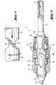
- the adapter 1 is a perspective, exploded illustration of a first exemplary embodiment of the adapter 1 according to the invention with the indicated tool holder 10 of a hammer drill, not shown, for example by the applicant.
- the adapter 1 essentially comprises a housing 2 and an intermediate striker 3 which can be locked in the housing 2.
- the intermediate striker 3 is equipped with an insertion end 4 which corresponds to the known insertion ends of the tools, for example the applicant, and has locking grooves and rotary driving grooves which interact with correspondingly designed counterparts in the tool holder of the hammer drill.
- the side of the adapter 1 facing away from the tool holder 10 of the hammer drill is designed with a holder 5 for the insertion end 7 of a tool 6 and is explained in more detail below.
- the intermediate striker 3 is equipped at its end opposite the insertion end 4 with scenes and / or driving surfaces 8. These interact with correspondingly designed sets and / or driving surfaces 9 at the insertion end of the tool 6. Due to the interacting backdrops and / or driving surfaces 8, 9 on the intermediate striker 3 and at the insertion end 7 of the tool 6, part of the momentum of the longitudinal impacts L generated by the hammer mechanism of the hammer drill is converted into a torque which, as a torsional impact component T, corresponds to the longitudinal impacts L. is superimposed, as indicated in Fig. 2. In this way, a drilling stroke is generated, which is transmitted to the tool 6, which is clamped in the receptacle 5 of the adapter 1 and rotates continuously during operation.
- the superimposition of the longitudinal impact component L and the torsion impact component T rotates the direction of the force vector on the cutting edge of the tool 6, which engages the surface to be machined, compared to a system consisting of conventional hammer drill with purely longitudinal impact support and conventional tool from the axial direction of the tool. Due to the changed direction of the force vector, the reinforcing steel is broken down by shear in the case of reinforcement hits. As a result, sudden torque peaks can be avoided when the tool is stuck and the safety for the user of the handheld device can be increased. But also in the case of mineral substrates without reinforcement, the shear effect of the drilling stroke supports the mining process.
- the longitudinal shock wave and the shaft of the torsion shock spread at different speeds in the tool.
- the different propagation speeds have little effect.
- the two shafts arrive largely simultaneously at the tool tip.
- the different propagation speeds can be used in a targeted manner.
- the tool tip first penetrates into the subsurface through the longitudinal impact and then breaks it down by shear due to the trailing torsion wave.
- the direction of the force vector on the cutting edge of the tool depends on the radius of the tool. In the middle of the cutting edge, the force always acts in the direction of the tool axis, regardless of the amount of torsional shock. Depending on the proportion of the torsional impact component, the direction of the force vector on the cutting edge tends with increasing radius.
- the generated twist impact has a total impact energy, which is composed of a torsional impact energy of the torsional impact component T and a longitudinal impact energy of the longitudinal impact component L.
- the following preferably applies 0.02 ⁇ E t / E t ⁇ D ⁇ 0.5, where E t stands for the rotary impact energy and E for the longitudinal impact energy and D, measured in mm, denotes the diameter of the tool 6 clamped in the receptacle 5 of the adapter 1.
- E t stands for the rotary impact energy
- E for the longitudinal impact energy
- D measured in mm
- the housing 1 is equipped at its end facing the tool holder 10 of the hammer drill with a cylindrical holder 13, which in the attached state receives a cylindrical extension 14 projecting from the tool holder 10 and supports it in operation in such a way that the intermediate striker 3 is relieved of the contact pressure applied by the user.
- the cylindrical extension 14 protruding from the tool holder 10 can at the same time be used for an even better transmission of the torque to the tool by being equipped on the inside with drivers 11 which engage in correspondingly designed rotary driving grooves 12 on the intermediate striker 3.
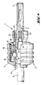
- FIG. 3 shows a further embodiment of the adapter according to the invention in partial axial section.
- the illustration shows the adapter 1 in the assembled state with a tool 6 inserted into the receptacle 5.
- the illustration of the tool receptacle of the hammer drill has been omitted.
- the housing 2 has a sleeve 17 which can be displaced axially against the force of a spring 18 and which interacts with locking rollers 19.
- the locking rollers 19 engage in locking grooves 20 at the tool end 7 and hold the tool.
- the intermediate striker 3 is held in a similar manner in the housing by means of locking rollers 21.
- the interacting backdrops and / or driving surfaces at the insertion end 7 of the tool 6 and at the intermediate striker 3 are indicated by the reference numerals 9 and 8.
- a device is again provided which decouples the housing 2 of the adapter from the pulse-like impacts occurring during operation.
- a prestressed spring element 15 is provided on the end of the adapter 1 facing the tool holder of the hammer drill (not shown), on which an annular collar 16 provided on the intermediate striker 3 is supported.
- the spring element 15 is preferably a plate spring, the spring force of which is approximately 300 N to approximately 1000 N, preferably approximately 500 N.
- the selected spring force ensures that the contact pressure normally applied by the user during operation is absorbed.
- the impact behavior thus remains largely independent of the contact pressure and thus remains stable.
- the housing 2 of the adapter 1 is decoupled from the impacts, since the stiffness of the plate spring 16 is much smaller than the stiffness of the interacting links and / or driving surfaces 8, 9.
- FIG. 4 shows a further exemplary embodiment of the adapter 1 according to the invention. Its structure largely corresponds to the adapter described with reference to FIG. 3, which is why analog reference numerals are also used for analog components. It can be seen from the exemplary embodiment shown that the locking elements 19 for the insertion end 7 of the tool 6 and those 21 for the intermediate striker 3 can also be spherical, for example. In contrast to the exemplary embodiment shown in FIG. 3, in the adapter 1 according to FIG. 1 the contact pressure applied by the user is transmitted directly via the system intermediate stopper 3 and insertion end 7 of the tool 6.
- a preferably spherical support element loaded by a spring 25 in the area of the interacting scenes and counter-scenes or driving surfaces 8, 9 26 arranged.
- Spring 25 and support element 26 can be fixed in the insertion end or, as shown, they can be arranged in the area of the driving surfaces 8 of the intermediate striker 3.
- the spring 25 is preferably a helical spring and has a spring force of approximately 300 N to approximately 1000 N, preferably approximately 500 N. With these spring forces, the intended periodic resetting of the tool still occurs despite the contact pressure usually applied by the user.
- a spring element 22 is arranged in the end region of the housing 2, which faces the tool holder (not shown) on the hand-held device , on which an annular collar 23 provided on the intermediate striker 3 is supported.
- the spring force of the spring element 22 is dimensioned and matched to the mass of the housing 2 in such a way that the housing 2 is not set to vibrate naturally by the impulse-like impacts that occur during operation.
- the adapter according to the invention was explained using the example of a hammer drill with a preferably electropneumatic hammer mechanism for longitudinal blows. It goes without saying that a hand-held device with a striking mechanism can also be provided, which generates torsional strikes. In this case, the scenes and / or driving surfaces interacting in the adapter are designed such that a longitudinal impact is produced on part of the torsional impact component. By overlaying the two striking components, a twist is generated.
- the direction of the force vector on the cutting edge of the tool acting on the surface to be machined is rotated, for example, relative to a tool with mere longitudinal impact support from the axial direction of the tool. Due to the changed direction of the force vector, the reinforcing steel is broken down by shear in the case of reinforcement hits. As a result, sudden torque peaks can be avoided when the tool is stuck and the safety for the user of the handheld device can be increased. But even on mineral substrates without reinforcement, the shear effect of the drill stroke supports the mining process. Due to the energetically more favorable mining process, the heat development is reduced, which is why additional cooling is not necessary even for larger diameter bores in particularly hard substrates.
- a hand-held device which is equipped, for example, with a striking mechanism for longitudinal strikes
- an adapter according to the invention which superimposes a torsional component on the longitudinal striking component in order to generate an impulsive drilling impact, also allows the efficient removal of brittle and / or ductile-failing substrates in dry use.
Landscapes
- Mechanical Engineering (AREA)
- Engineering & Computer Science (AREA)
- Percussive Tools And Related Accessories (AREA)
- Ultra Sonic Daignosis Equipment (AREA)
- Feeding Of Articles To Conveyors (AREA)
- Forging (AREA)
- Apparatus For Radiation Diagnosis (AREA)
- Drilling Tools (AREA)
- Constituent Portions Of Griding Lathes, Driving, Sensing And Control (AREA)
- Portable Nailing Machines And Staplers (AREA)
- Refuse Receptacles (AREA)
- Refuse Collection And Transfer (AREA)
- Sampling And Sample Adjustment (AREA)
- Processing Of Stones Or Stones Resemblance Materials (AREA)
Applications Claiming Priority (4)
| Application Number | Priority Date | Filing Date | Title |
|---|---|---|---|
| DE19510964A DE19510964A1 (de) | 1995-03-24 | 1995-03-24 | Handgerät zur trockenen materialabtragenden Bearbeitung von spröden und/oder duktil versagenden Bauteilen und Adapter für ein Hammerbohrgerät |
| DE19510964 | 1995-03-24 | ||
| DE19531389 | 1995-08-26 | ||
| DE1995131389 DE19531389A1 (de) | 1995-08-26 | 1995-08-26 | Vorrichtung zur Übertragung von impulsartigen Schlägen auf ein kontinuierlich rotierendes Werkzeug |
Publications (2)
| Publication Number | Publication Date |
|---|---|
| EP0733443A1 true EP0733443A1 (fr) | 1996-09-25 |
| EP0733443B1 EP0733443B1 (fr) | 1997-10-29 |
Family
ID=26013732
Family Applications (1)
| Application Number | Title | Priority Date | Filing Date |
|---|---|---|---|
| EP96810017A Expired - Lifetime EP0733443B1 (fr) | 1995-03-24 | 1996-01-09 | Dispositif pour transmettre des coups par impulsion sur un outil à rotation continue |
Country Status (12)
| Country | Link |
|---|---|
| US (1) | US5820312A (fr) |
| EP (1) | EP0733443B1 (fr) |
| JP (1) | JPH08257942A (fr) |
| KR (1) | KR960033659A (fr) |
| CN (1) | CN1053856C (fr) |
| AT (1) | ATE159677T1 (fr) |
| AU (1) | AU702744B2 (fr) |
| CA (1) | CA2172090A1 (fr) |
| DE (1) | DE59600036D1 (fr) |
| DK (1) | DK0733443T3 (fr) |
| FI (1) | FI961301L (fr) |
| HU (1) | HUP9600720A3 (fr) |
Cited By (1)
| Publication number | Priority date | Publication date | Assignee | Title |
|---|---|---|---|---|
| US10018650B2 (en) | 2014-02-17 | 2018-07-10 | Robert Bosch Gmbh | Rocker device for a micromechanical Z sensor |
Families Citing this family (27)
| Publication number | Priority date | Publication date | Assignee | Title |
|---|---|---|---|---|
| US6402701B1 (en) | 1999-03-23 | 2002-06-11 | Fna Concepts, Llc | Biopsy needle instrument |
| DE19952225A1 (de) * | 1999-10-29 | 2001-05-03 | Hilti Ag | Bohr- und/oder Meisselwerkzeug |
| DE19961586A1 (de) * | 1999-12-21 | 2001-07-05 | Bosch Gmbh Robert | Schlagunterstützte Handbohrmaschine |
| JP2001302649A (ja) * | 2000-04-28 | 2001-10-31 | Sumitomo Chem Co Ltd | プロピレンオキサイドの精製方法 |
| DE10021355B4 (de) * | 2000-05-02 | 2005-04-28 | Hilti Ag | Schlagendes Elektrohandwerkzeuggerät mit schwingungsentkoppelten Baugruppen |
| FR2808720B1 (fr) * | 2000-05-12 | 2002-07-26 | Montabert Ets | Appareil a percussion du type brise-roche |
| DE10047021A1 (de) * | 2000-09-22 | 2002-04-18 | Bosch Gmbh Robert | Handwerkzeugmachine mit einer abnehmbaren Werkzeughalterung |
| CA2390826C (fr) | 2002-06-17 | 2009-10-13 | Bob B. Ha | Marteau perforateur |
| EP1504852B1 (fr) * | 2003-08-06 | 2010-04-21 | Hitachi Koki Co., Ltd. | Perceuse à percussion |
| JP2005052902A (ja) * | 2003-08-06 | 2005-03-03 | Hitachi Koki Co Ltd | 振動ドリル |
| US20060100492A1 (en) * | 2004-10-29 | 2006-05-11 | Medtronic, Inc. | Intra-esophageal catheter |
| GB2422569A (en) * | 2005-01-26 | 2006-08-02 | Black & Decker Inc | Rotary hammer |
| US8007210B2 (en) * | 2007-10-26 | 2011-08-30 | P. V. Tools, Inc. | System and method for breaking chips formed by a drilling operation |
| DE102010030098A1 (de) * | 2010-06-15 | 2011-12-15 | Hilti Aktiengesellschaft | Eintreibvorrichtung |
| DE102010031499A1 (de) * | 2010-07-19 | 2012-01-19 | Robert Bosch Gmbh | Handwerkzeugmaschine mit einem mechanischen Schlagwerk |
| CN102207420B (zh) * | 2011-03-15 | 2012-10-10 | 清华大学 | 主轴与刀柄结合面静动态特性试验装置及试验方法 |
| FR2984192B1 (fr) | 2011-12-16 | 2014-01-10 | Mitis | Procede d'usinage |
| DE102012209446A1 (de) * | 2012-06-05 | 2013-12-05 | Robert Bosch Gmbh | Handwerkzeugmaschinenvorrichtung |
| WO2014075165A1 (fr) * | 2012-11-14 | 2014-05-22 | British Columbia Cancer Agency Branch | Accessoire de marteau perforateur tubulaire |
| DE102015206634A1 (de) * | 2015-04-14 | 2016-10-20 | Robert Bosch Gmbh | Werkzeugvorsatz für eine Handwerkzeugmaschine |
| EP3213844A1 (fr) | 2016-03-03 | 2017-09-06 | HILTI Aktiengesellschaft | Outil de carottage portatif electrique |
| CN111331559A (zh) * | 2018-12-18 | 2020-06-26 | 宝时得科技(中国)有限公司 | 电镐转接组件以及电镐 |
| US12576496B2 (en) * | 2019-10-31 | 2026-03-17 | Adam Douglas Carter | Universal chisel attachment |
| US20210129311A1 (en) * | 2019-10-31 | 2021-05-06 | Adam Carter | Universal Chisel Attachment |
| CN112476647B (zh) * | 2020-12-16 | 2022-05-03 | 杭州鎏金庐亮空间设计有限公司 | 一种钻木工具 |
| CN112454545B (zh) * | 2020-12-16 | 2022-04-29 | 杭州鎏金庐亮空间设计有限公司 | 一种木材加工过程中使用的钻孔设备 |
| US20240238878A1 (en) * | 2023-01-13 | 2024-07-18 | The Boeing Company | Drilling apparatus |
Citations (3)
| Publication number | Priority date | Publication date | Assignee | Title |
|---|---|---|---|---|
| DE2834991A1 (de) * | 1978-08-10 | 1980-02-14 | Joran Bor A S | Werkzeughalterung fuer bohrhammer, schlagbohrmaschine o.dgl. |
| GB2166075A (en) * | 1984-10-27 | 1986-04-30 | Bosch Gmbh Robert | Angle attachment for transmitting and deflecting drive power |
| DE3637354A1 (de) * | 1986-11-03 | 1988-05-05 | Bosch Gmbh Robert | Werkzeughalter |
Family Cites Families (4)
| Publication number | Priority date | Publication date | Assignee | Title |
|---|---|---|---|---|
| US1665173A (en) * | 1925-08-10 | 1928-04-03 | John I Misener | Hammer attachment for electric drills and the like |
| US2556163A (en) * | 1947-11-01 | 1951-06-12 | Harry D Cummins | Rotary drill |
| US2724573A (en) * | 1954-07-26 | 1955-11-22 | Axel E Lundquist | Percussion attachment for portable drills |
| CN2098341U (zh) * | 1991-05-20 | 1992-03-11 | 庄建龙 | 一种电钻变冲击电钻的装置 |
-
1996
- 1996-01-09 DE DE59600036T patent/DE59600036D1/de not_active Expired - Fee Related
- 1996-01-09 EP EP96810017A patent/EP0733443B1/fr not_active Expired - Lifetime
- 1996-01-09 DK DK96810017T patent/DK0733443T3/da active
- 1996-01-09 AT AT96810017T patent/ATE159677T1/de active
- 1996-03-05 KR KR1019960005652A patent/KR960033659A/ko not_active Abandoned
- 1996-03-19 CA CA002172090A patent/CA2172090A1/fr not_active Abandoned
- 1996-03-20 AU AU48203/96A patent/AU702744B2/en not_active Ceased
- 1996-03-21 FI FI961301A patent/FI961301L/fi unknown
- 1996-03-22 HU HU9600720A patent/HUP9600720A3/hu unknown
- 1996-03-22 CN CN96103729A patent/CN1053856C/zh not_active Expired - Fee Related
- 1996-03-25 JP JP8068243A patent/JPH08257942A/ja active Pending
- 1996-03-25 US US08/621,387 patent/US5820312A/en not_active Expired - Lifetime
Patent Citations (3)
| Publication number | Priority date | Publication date | Assignee | Title |
|---|---|---|---|---|
| DE2834991A1 (de) * | 1978-08-10 | 1980-02-14 | Joran Bor A S | Werkzeughalterung fuer bohrhammer, schlagbohrmaschine o.dgl. |
| GB2166075A (en) * | 1984-10-27 | 1986-04-30 | Bosch Gmbh Robert | Angle attachment for transmitting and deflecting drive power |
| DE3637354A1 (de) * | 1986-11-03 | 1988-05-05 | Bosch Gmbh Robert | Werkzeughalter |
Cited By (1)
| Publication number | Priority date | Publication date | Assignee | Title |
|---|---|---|---|---|
| US10018650B2 (en) | 2014-02-17 | 2018-07-10 | Robert Bosch Gmbh | Rocker device for a micromechanical Z sensor |
Also Published As
| Publication number | Publication date |
|---|---|
| DE59600036D1 (de) | 1997-12-04 |
| FI961301A7 (fi) | 1996-09-25 |
| DK0733443T3 (da) | 1998-07-20 |
| CA2172090A1 (fr) | 1996-09-25 |
| FI961301A0 (fi) | 1996-03-21 |
| ATE159677T1 (de) | 1997-11-15 |
| FI961301L (fi) | 1996-09-25 |
| JPH08257942A (ja) | 1996-10-08 |
| CN1137967A (zh) | 1996-12-18 |
| CN1053856C (zh) | 2000-06-28 |
| AU702744B2 (en) | 1999-03-04 |
| EP0733443B1 (fr) | 1997-10-29 |
| HUP9600720A2 (en) | 1996-10-28 |
| KR960033659A (ko) | 1996-10-22 |
| US5820312A (en) | 1998-10-13 |
| HUP9600720A3 (en) | 1999-09-28 |
| HU9600720D0 (en) | 1996-05-28 |
| AU4820396A (en) | 1996-10-03 |
Similar Documents
| Publication | Publication Date | Title |
|---|---|---|
| EP0733443B1 (fr) | Dispositif pour transmettre des coups par impulsion sur un outil à rotation continue | |
| EP0733442B1 (fr) | Marteau perforateur pour béton armé | |
| EP1882559B1 (fr) | Outil à main doté d'un dispositif de découplage | |
| EP0976505B1 (fr) | Machine à forer portable | |
| EP2425937B1 (fr) | Machine-outil à main | |
| EP1326736B1 (fr) | Porte-outil pour une machine-outil | |
| EP1862265A2 (fr) | Machine-outil manuelle dotée d'un dispositif d'accouplement à patinage | |
| DE3439475A1 (de) | Winkelvorsatz zur uebertragung und umlenkung der antriebsenergie | |
| DE19621090A1 (de) | Schlagbohrmaschine | |
| EP0856371B1 (fr) | Dispositif de transfert d'impulses axiaux sur un outil de forage | |
| EP3648928B1 (fr) | Outil de pose, kit pour système d'outil de pose et système d'outil de pose | |
| DE10241054A1 (de) | Werkzeug und Werkzeughalter für eine Handwerkzeugmaschine | |
| EP1716980B1 (fr) | Outil portatif avec entraînement à basculement | |
| DE3310147C2 (fr) | ||
| EP0663270B1 (fr) | Marteau à percussion rotative et/ou rectiligne | |
| DE3743817C2 (de) | Gesteins-, Bohr- und Meisselwerkzeug | |
| EP0808696B1 (fr) | Système de fixation et procédé de réalisation de fixations | |
| EP2132005B1 (fr) | Mécanisme rotopercutant | |
| DE19531389A1 (de) | Vorrichtung zur Übertragung von impulsartigen Schlägen auf ein kontinuierlich rotierendes Werkzeug | |
| DE102006035417B4 (de) | Handwerkzeugmaschine | |
| DE102021213370A1 (de) | Vibrationsbohrhammer | |
| WO2021213857A1 (fr) | Outil électrique à main doté d'un accouplement à encliquetage à bille | |
| EP1795308A2 (fr) | Appareil à percussion | |
| EP1498220B1 (fr) | Machine outil pour la rotation accouplée d'un outil ou d'outils multiples | |
| EP1162037B1 (fr) | Dispositif de rotation-percussion pour une tige de forage |
Legal Events
| Date | Code | Title | Description |
|---|---|---|---|
| PUAI | Public reference made under article 153(3) epc to a published international application that has entered the european phase |
Free format text: ORIGINAL CODE: 0009012 |
|
| AK | Designated contracting states |
Kind code of ref document: A1 Designated state(s): AT BE CH DE DK FR GB IT LI NL SE |
|
| 17P | Request for examination filed |
Effective date: 19961012 |
|
| GRAG | Despatch of communication of intention to grant |
Free format text: ORIGINAL CODE: EPIDOS AGRA |
|
| 17Q | First examination report despatched |
Effective date: 19961127 |
|
| GRAH | Despatch of communication of intention to grant a patent |
Free format text: ORIGINAL CODE: EPIDOS IGRA |
|
| GRAH | Despatch of communication of intention to grant a patent |
Free format text: ORIGINAL CODE: EPIDOS IGRA |
|
| GRAA | (expected) grant |
Free format text: ORIGINAL CODE: 0009210 |
|
| ITF | It: translation for a ep patent filed | ||
| AK | Designated contracting states |
Kind code of ref document: B1 Designated state(s): AT BE CH DE DK FR GB IT LI NL SE |
|
| REF | Corresponds to: |
Ref document number: 159677 Country of ref document: AT Date of ref document: 19971115 Kind code of ref document: T |
|
| REG | Reference to a national code |
Ref country code: CH Ref legal event code: EP |
|
| REF | Corresponds to: |
Ref document number: 59600036 Country of ref document: DE Date of ref document: 19971204 |
|
| ET | Fr: translation filed | ||
| GBT | Gb: translation of ep patent filed (gb section 77(6)(a)/1977) |
Effective date: 19980113 |
|
| REG | Reference to a national code |
Ref country code: DK Ref legal event code: T3 |
|
| PLBE | No opposition filed within time limit |
Free format text: ORIGINAL CODE: 0009261 |
|
| STAA | Information on the status of an ep patent application or granted ep patent |
Free format text: STATUS: NO OPPOSITION FILED WITHIN TIME LIMIT |
|
| 26N | No opposition filed | ||
| PGFP | Annual fee paid to national office [announced via postgrant information from national office to epo] |
Ref country code: SE Payment date: 20010105 Year of fee payment: 6 |
|
| PGFP | Annual fee paid to national office [announced via postgrant information from national office to epo] |
Ref country code: DK Payment date: 20010116 Year of fee payment: 6 Ref country code: AT Payment date: 20010116 Year of fee payment: 6 |
|
| PGFP | Annual fee paid to national office [announced via postgrant information from national office to epo] |
Ref country code: NL Payment date: 20010131 Year of fee payment: 6 |
|
| PGFP | Annual fee paid to national office [announced via postgrant information from national office to epo] |
Ref country code: BE Payment date: 20010314 Year of fee payment: 6 |
|
| REG | Reference to a national code |
Ref country code: GB Ref legal event code: IF02 |
|
| PG25 | Lapsed in a contracting state [announced via postgrant information from national office to epo] |
Ref country code: DK Free format text: LAPSE BECAUSE OF NON-PAYMENT OF DUE FEES Effective date: 20020109 Ref country code: AT Free format text: LAPSE BECAUSE OF NON-PAYMENT OF DUE FEES Effective date: 20020109 |
|
| PG25 | Lapsed in a contracting state [announced via postgrant information from national office to epo] |
Ref country code: SE Free format text: LAPSE BECAUSE OF NON-PAYMENT OF DUE FEES Effective date: 20020110 |
|
| PG25 | Lapsed in a contracting state [announced via postgrant information from national office to epo] |
Ref country code: BE Free format text: LAPSE BECAUSE OF NON-PAYMENT OF DUE FEES Effective date: 20020131 |
|
| BERE | Be: lapsed |
Owner name: HILTI A.G. Effective date: 20020131 |
|
| PG25 | Lapsed in a contracting state [announced via postgrant information from national office to epo] |
Ref country code: NL Free format text: LAPSE BECAUSE OF NON-PAYMENT OF DUE FEES Effective date: 20020801 |
|
| EUG | Se: european patent has lapsed |
Ref document number: 96810017.2 |
|
| NLV4 | Nl: lapsed or anulled due to non-payment of the annual fee |
Effective date: 20020801 |
|
| PG25 | Lapsed in a contracting state [announced via postgrant information from national office to epo] |
Ref country code: IT Free format text: LAPSE BECAUSE OF NON-PAYMENT OF DUE FEES Effective date: 20050109 |
|
| PGFP | Annual fee paid to national office [announced via postgrant information from national office to epo] |
Ref country code: DE Payment date: 20081219 Year of fee payment: 14 |
|
| PGFP | Annual fee paid to national office [announced via postgrant information from national office to epo] |
Ref country code: GB Payment date: 20090107 Year of fee payment: 14 Ref country code: CH Payment date: 20090114 Year of fee payment: 14 |
|
| PGFP | Annual fee paid to national office [announced via postgrant information from national office to epo] |
Ref country code: FR Payment date: 20090113 Year of fee payment: 14 |
|
| REG | Reference to a national code |
Ref country code: CH Ref legal event code: PL |
|
| GBPC | Gb: european patent ceased through non-payment of renewal fee |
Effective date: 20100109 |
|
| REG | Reference to a national code |
Ref country code: FR Ref legal event code: ST Effective date: 20100930 |
|
| PG25 | Lapsed in a contracting state [announced via postgrant information from national office to epo] |
Ref country code: LI Free format text: LAPSE BECAUSE OF NON-PAYMENT OF DUE FEES Effective date: 20100131 Ref country code: FR Free format text: LAPSE BECAUSE OF NON-PAYMENT OF DUE FEES Effective date: 20100201 Ref country code: CH Free format text: LAPSE BECAUSE OF NON-PAYMENT OF DUE FEES Effective date: 20100131 |
|
| PG25 | Lapsed in a contracting state [announced via postgrant information from national office to epo] |
Ref country code: DE Free format text: LAPSE BECAUSE OF NON-PAYMENT OF DUE FEES Effective date: 20100803 |
|
| PG25 | Lapsed in a contracting state [announced via postgrant information from national office to epo] |
Ref country code: GB Free format text: LAPSE BECAUSE OF NON-PAYMENT OF DUE FEES Effective date: 20100109 |