EP0733577A2 - Emergency drive unit for an elevator machinery - Google Patents
Emergency drive unit for an elevator machinery Download PDFInfo
- Publication number
- EP0733577A2 EP0733577A2 EP96104740A EP96104740A EP0733577A2 EP 0733577 A2 EP0733577 A2 EP 0733577A2 EP 96104740 A EP96104740 A EP 96104740A EP 96104740 A EP96104740 A EP 96104740A EP 0733577 A2 EP0733577 A2 EP 0733577A2
- Authority
- EP
- European Patent Office
- Prior art keywords
- drive unit
- emergency drive
- emergency
- rotor
- motor
- Prior art date
- Legal status (The legal status is an assumption and is not a legal conclusion. Google has not performed a legal analysis and makes no representation as to the accuracy of the status listed.)
- Granted
Links
- 239000007858 starting material Substances 0.000 claims description 4
- 238000002485 combustion reaction Methods 0.000 claims description 3
- 238000010586 diagram Methods 0.000 description 3
- 238000000034 method Methods 0.000 description 3
- 238000003825 pressing Methods 0.000 description 2
- 230000002457 bidirectional effect Effects 0.000 description 1
- 230000005540 biological transmission Effects 0.000 description 1
- 238000012512 characterization method Methods 0.000 description 1
- 238000010276 construction Methods 0.000 description 1
- 230000005415 magnetization Effects 0.000 description 1
- 238000004519 manufacturing process Methods 0.000 description 1
Images
Classifications
-
- B—PERFORMING OPERATIONS; TRANSPORTING
- B66—HOISTING; LIFTING; HAULING
- B66B—ELEVATORS; ESCALATORS OR MOVING WALKWAYS
- B66B11/00—Main component parts of lifts in, or associated with, buildings or other structures
- B66B11/04—Driving gear ; Details thereof, e.g. seals
-
- B—PERFORMING OPERATIONS; TRANSPORTING
- B66—HOISTING; LIFTING; HAULING
- B66B—ELEVATORS; ESCALATORS OR MOVING WALKWAYS
- B66B5/00—Applications of checking, fault-correcting, or safety devices in elevators
- B66B5/02—Applications of checking, fault-correcting, or safety devices in elevators responsive to abnormal operating conditions
- B66B5/027—Applications of checking, fault-correcting, or safety devices in elevators responsive to abnormal operating conditions to permit passengers to leave an elevator car in case of failure, e.g. moving the car to a reference floor or unlocking the door
Definitions
- the present invention relates to a device as defined in the preamble of claim 1 for driving an elevator machinery in an emergency, such as a power failure.
- the object of the present invention is to produce a simple and low-cost solution especially for driving an elevator motor provided with a discoidal rotor in an emergency, e.g. in a situation where the elevator car has stopped between floors.
- the device of the invention is characterized by what is said in the characterization part of claim 1.
- Other embodiments of the invention are characterized by the features presented in the other claims.
- the rotor disc is provided with a gear rim which is driven by means of power transmission device, which in one of the embodiments of the invention consists of a manual drive latch.
- the gear rim is engaged by a gear wheel driven by a motor, said gear wheel being driven by an application of a device used for the starting of combustion engines, known in itself.
- the emergency drive unit is very advantageous in respect of price and it is independent of the equipment controlling the elevator during normal operation.
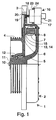
- Fig. 1 presents an elevator machinery 1 comprising an elevator motor 2 shown in a partly sectioned form, a brake 3, a traction sheave 4 and an emergency drive unit 16 as provided by the invention.
- the elevator motor 2 comprises a stator 5 and a rotor 6.
- the stator is a trough-shaped body of revolution with one side open, with a stator core packet 7 attached to it by means of fixing elements 8. Between the outer circles of the stator and rotor there is either a sliding seal or a labyrinth seal.
- the motor is fixed in place by the stator by means of fixing bolts 10.
- Bearings 12 are provided between the stator shaft 11 and the rotor 6.
- the rotor 6 is of a discoidal construction and its magnetization is implemented using e.g.
- the permanent magnets 14 mounted in a circle on the rotor surface. Between the permanent magnets 14 and the stator core packet 7 is a planar air gap 15, the plane of which is perpendicular to the stator shaft 11. The traction sheave 4 is attached to the rotor 6.
- the emergency drive unit 16 comprises a drive motor 17, a solenoid 21, and a power output of the motor, a gear wheel 18 and, attached to the rotor 6, a gear rim 19 by means of which the emergency drive unit 16 rotates the rotor 6.
- the gear rim 19 is placed on the inside of the brake rim 20.
- the drive motor 17 of the emergency drive unit 16 together with its auxiliary equipment is fixed to a flange 24 in the stator structure 5 by means of screws 23.
- the drive motor 17 with its auxiliary equipment is a starter motor, known in itself, as used for the starting of combustion engines, such as car engines, comprising the required motor, solenoid, switch and Bendix gear.
- the starter motors used in cars are generally direct-current series motors and are normally driven in one direction only.
- Fig. 3 shows a diagram of a reversing circuit designed for use in an elevator drive.
- the operation of the emergency drive unit is as follows: Electric power is supplied to the drive motor 17 and solenoid 21, causing the gear wheel 18 to move onto the gear rim 19. At the same time, the brake 3 is released, with the result that the drive motor 17 begins to rotate the rotor and the elevator starts moving in a direction determined by the direction of rotation of the drive motor.
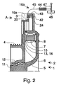
- Fig. 2 presents an alternative placement of the gear rim together with a manual drive latch.
- the gear rim 19a is now placed beside the brake rim 20.
- the traction sheave 4, brake rim 20 and gear rim 19a are preferably manufactured as an integrated structure with the rotor 6. It is naturally possible in the case of both Fig. 1 and Fig. 2 to manufacture the gear rim as a separate part which is then attached to the rotor.
- the gear rim is provided with wedge-shaped teeth (Fig. 4).
- the gear rim 19a is driven by a manual emergency drive unit 16a, which comprises a wedge-shaped latch 39 (Fig. 4), which is moved backwards and forwards by means of a manual lever 47.
- the power from the lever to the latch is transmitted by means of a flexible wire or wire cable 45 placed in a flexible tube 44.
- the emergency drive unit 16a is fixed to a flange 24 in the stator structure 5 by means of fixing elements 42, preferably screws.
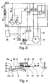
- Fig. 3 presents the circuit diagram of an electric emergency drive unit 16 designed for bidirectional operation.
- the operating voltage DC+ and DC- for the emergency drive unit is obtained from a d.c. source 26, e.g. a 12 V battery, via a main switch 27.
- the negative terminal DC- is not connected to earth because the change of running direction of the drive motor is effected by changing the polarity by means of two contactors 31 and 32.
- Connected in series with the coils of the contactors is a contactor 28 for locking the elevator drive 25.
- pressing button 29 the elevator is driven upwards via contactor 31, and by pressing button 20, it is driven downwards via contactor 32.
- one contact 33 and 34 passes a current to the solenoid 21, which moves the gear wheel 18 into mesh with the gear rim 19 (Fig. 1-2).
- Starter motors usually have their own contact, which is not used in this circuit.
- the brake 3 is connected in parallel with the solenoid 21. In normal elevator operation, the brake receives its operating voltage through the elevator drive 25.
- the other two contacts, 35-36 and 37-38 form part of the reversing circuit, i.e. they change the polarity of the voltage supplied to the motor 17.
- Fig. 4 presents a manual emergency drive unit 16a as seen from direction A shown in Fig. 2.
- a gear rim 19a provided with wedge-shaped teeth.
- the gear rim is driven by a manual emergency drive unit 16a.
- the emergency drive unit comprises a wedge-shaped latch 39, which is moved back and forth by means of a manual lever 47.
- the power from the lever to the latch is transmitted by means of a flexible wire or wire cable 45 placed in a flexible tube 44, one end of the wire or cable being attached to the lever and the other to the latch 39.
- the emergency drive unit 16a is fixed to a flange 24 in the stator structure 5 by means of fixing elements 42.
- the lever 47 is pivoted on a base 46.
- the lever is turned back and forth in directions L and R, causing the wire 45 in the flexible tube 44 to move back and forth as well and therefore the latch to move with it.
- the latch is supported by a sleeve bearing 40 laid in the direction of the movement.
- the sleeve bearing 40 is pivoted on the frame 43 and provided with a spring 41.
- the brake 3 of the elevator is released when the lever is pulled in direction R, and when the lever is pushed in direction L, the brake is closed by means of a separate device, e.g. a separate wire/tube arrangement or a separate electric control signal to the brake to release it.
- the elevator is driven in this manner until it has reached the desired landing.
- the manual emergency drive unit 16a is provided with a shifter enabling the whole emergency drive unit to be shifted up so that the wedge-shaped latch 39 is completely out of contact with the gear rim 19a. However, this shifter is not shown in the figures.
- the manual emergency drive unit 16a can additionally be provided with an arrester 48 to prevent the rotor 6 from turning backwards while the lever is being pushed in direction L.
- the arrester 48 is mounted with a joint 49 on the stator 5.
- a spring 50 is mounted between the arrester 48 and the stator 5 to press the arrester against the gear rim 19a.
Landscapes
- Engineering & Computer Science (AREA)
- Civil Engineering (AREA)
- Mechanical Engineering (AREA)
- Structural Engineering (AREA)
- Maintenance And Inspection Apparatuses For Elevators (AREA)
- Cage And Drive Apparatuses For Elevators (AREA)
- Connection Of Motors, Electrical Generators, Mechanical Devices, And The Like (AREA)
Abstract
Description
- The present invention relates to a device as defined in the preamble of
claim 1 for driving an elevator machinery in an emergency, such as a power failure. - According to elevator regulations, when an elevator stops between floors, there must be a possibility to move the elevator car to a suitable floor. To achieve this, several methods are used, such as releasing the brake manually by means of a suitable tool. If the position and load of the elevator are such that the elevator will start moving, then releasing the brake is an applicable method. If the elevator and its counterweight are in equilibrium, it is necessary to rotate the elevator motor by means of a suitable device.
- For this purpose, battery operated inverters can be used. However, they are expensive and more susceptible to failure than simpler electric drives and manual methods. Specification US 4,376,471 presents a solution based on the use of an inverter in an emergency. The inverter is used to drive the elevator motor, so it does not provide a solution to an interruption of operation caused by the motor.
- The object of the present invention is to produce a simple and low-cost solution especially for driving an elevator motor provided with a discoidal rotor in an emergency, e.g. in a situation where the elevator car has stopped between floors.
- To achieve the above objects, the device of the invention is characterized by what is said in the characterization part of
claim 1. Other embodiments of the invention are characterized by the features presented in the other claims. - In the emergency drive unit of the invention, the rotor disc is provided with a gear rim which is driven by means of power transmission device, which in one of the embodiments of the invention consists of a manual drive latch. In another embodiment, the gear rim is engaged by a gear wheel driven by a motor, said gear wheel being driven by an application of a device used for the starting of combustion engines, known in itself. The emergency drive unit is very advantageous in respect of price and it is independent of the equipment controlling the elevator during normal operation.
- In the following, the invention is described by the aid of two embodiments, in which
- Fig. 1
- presents an electric emergency drive unit as provided by the invention, applied to a discoidal motor,
- Fig. 2
- presents a manual emergency drive unit as provided by the invention,
- Fig. 3
- presents a circuit diagram for the electric emergency drive unit, and
- Fig. 4
- presents the manual emergency drive unit in side view.
- Fig. 1 presents an
elevator machinery 1 comprising anelevator motor 2 shown in a partly sectioned form, abrake 3, atraction sheave 4 and anemergency drive unit 16 as provided by the invention. Theelevator motor 2 comprises astator 5 and arotor 6. The stator is a trough-shaped body of revolution with one side open, with astator core packet 7 attached to it by means offixing elements 8. Between the outer circles of the stator and rotor there is either a sliding seal or a labyrinth seal. The motor is fixed in place by the stator by means of fixingbolts 10.Bearings 12 are provided between thestator shaft 11 and therotor 6. Therotor 6 is of a discoidal construction and its magnetization is implemented using e.g. permanent magnets 14 mounted in a circle on the rotor surface. Between the permanent magnets 14 and thestator core packet 7 is aplanar air gap 15, the plane of which is perpendicular to thestator shaft 11. Thetraction sheave 4 is attached to therotor 6. - The
emergency drive unit 16 comprises adrive motor 17, asolenoid 21, and a power output of the motor, agear wheel 18 and, attached to therotor 6, agear rim 19 by means of which theemergency drive unit 16 rotates therotor 6. Thegear rim 19 is placed on the inside of thebrake rim 20. Thedrive motor 17 of theemergency drive unit 16 together with its auxiliary equipment is fixed to aflange 24 in thestator structure 5 by means ofscrews 23. Thedrive motor 17 with its auxiliary equipment is a starter motor, known in itself, as used for the starting of combustion engines, such as car engines, comprising the required motor, solenoid, switch and Bendix gear. The starter motors used in cars are generally direct-current series motors and are normally driven in one direction only. Fig. 3 shows a diagram of a reversing circuit designed for use in an elevator drive. - The operation of the emergency drive unit is as follows: Electric power is supplied to the
drive motor 17 andsolenoid 21, causing thegear wheel 18 to move onto thegear rim 19. At the same time, thebrake 3 is released, with the result that thedrive motor 17 begins to rotate the rotor and the elevator starts moving in a direction determined by the direction of rotation of the drive motor. - Fig. 2 presents an alternative placement of the gear rim together with a manual drive latch. The
gear rim 19a is now placed beside thebrake rim 20. Thetraction sheave 4,brake rim 20 andgear rim 19a are preferably manufactured as an integrated structure with therotor 6. It is naturally possible in the case of both Fig. 1 and Fig. 2 to manufacture the gear rim as a separate part which is then attached to the rotor. In this embodiment, the gear rim is provided with wedge-shaped teeth (Fig. 4). In this case, thegear rim 19a is driven by a manualemergency drive unit 16a, which comprises a wedge-shaped latch 39 (Fig. 4), which is moved backwards and forwards by means of amanual lever 47. The power from the lever to the latch is transmitted by means of a flexible wire orwire cable 45 placed in aflexible tube 44. Theemergency drive unit 16a is fixed to aflange 24 in thestator structure 5 by means offixing elements 42, preferably screws. - Fig. 3 presents the circuit diagram of an electric
emergency drive unit 16 designed for bidirectional operation. The operating voltage DC+ and DC- for the emergency drive unit is obtained from a d.c.source 26, e.g. a 12 V battery, via amain switch 27. The negative terminal DC- is not connected to earth because the change of running direction of the drive motor is effected by changing the polarity by means of twocontactors contactor 28 for locking theelevator drive 25. By pressingbutton 29, the elevator is driven upwards viacontactor 31, and by pressingbutton 20, it is driven downwards viacontactor 32. In each of these contactors, onecontact solenoid 21, which moves thegear wheel 18 into mesh with the gear rim 19 (Fig. 1-2). Starter motors usually have their own contact, which is not used in this circuit. Thebrake 3 is connected in parallel with thesolenoid 21. In normal elevator operation, the brake receives its operating voltage through theelevator drive 25. In eachcontactor motor 17. - Fig. 4 presents a manual
emergency drive unit 16a as seen from direction A shown in Fig. 2. Beside thebrake rim 20 on the circumference of therotor 6 is agear rim 19a provided with wedge-shaped teeth. The gear rim is driven by a manualemergency drive unit 16a. The emergency drive unit comprises a wedge-shaped latch 39, which is moved back and forth by means of amanual lever 47. The power from the lever to the latch is transmitted by means of a flexible wire orwire cable 45 placed in aflexible tube 44, one end of the wire or cable being attached to the lever and the other to thelatch 39. Theemergency drive unit 16a is fixed to aflange 24 in thestator structure 5 by means of fixingelements 42. Thelever 47 is pivoted on abase 46. The lever is turned back and forth in directions L and R, causing thewire 45 in theflexible tube 44 to move back and forth as well and therefore the latch to move with it. The latch is supported by asleeve bearing 40 laid in the direction of the movement. Thesleeve bearing 40 is pivoted on theframe 43 and provided with aspring 41. When the lever is pulled in direction R, thewire 45 draws thelatch 39 and the tooth engaged by it, causing the rotor to turn through a corresponding distance and thus moving the elevator. When the lever is pushed in direction L, the latch rises over the wedge-shaped tooth of the gear rim and then slips down again, engaging the next tooth. Thebrake 3 of the elevator is released when the lever is pulled in direction R, and when the lever is pushed in direction L, the brake is closed by means of a separate device, e.g. a separate wire/tube arrangement or a separate electric control signal to the brake to release it. The elevator is driven in this manner until it has reached the desired landing. The manualemergency drive unit 16a is provided with a shifter enabling the whole emergency drive unit to be shifted up so that the wedge-shapedlatch 39 is completely out of contact with thegear rim 19a. However, this shifter is not shown in the figures. The manualemergency drive unit 16a can additionally be provided with anarrester 48 to prevent therotor 6 from turning backwards while the lever is being pushed in direction L. Thearrester 48 is mounted with a joint 49 on thestator 5. Aspring 50 is mounted between thearrester 48 and thestator 5 to press the arrester against thegear rim 19a. Using an arrester provides the advantage that thebrake 3 need not be closed to prevent reverse rotation, but the brake can remain released all the time when the manual emergency drive unit is being operated. - It is obvious to a person skilled in the art that the embodiments of the invention are not restricted to the examples described above, but that they may instead be varied in the scope of the following claims.
Claims (8)
- Emergency drive unit for an elevator motor to move an elevator, said elevator motor comprising a stator (5) and a discoidal rotor (6) with a planar air gap (15) between them, the plane of which air gap is substantially perpendicular to the shaft (11) of the elevator motor (2), characterized in that the emergency drive unit (16) consists of a gear rim (19) attached to the rotor (6) and placed in conjunction with its periphery and a drive unit used to rotate the rotor (6) by means of the gear rim (19).
- Emergency drive unit (16) as defined in claim 1, characterized in that the gear rim (19) is on the underside of a brake rim (20) placed in conjunction with the periphery of the rotor disc.
- Emergency drive unit (16) as defined in claim 1, characterized in that the gear rim (19) is on the top side beside a brake rim (20) placed in conjunction with the periphery of the rotor disc.
- Emergency drive unit (16) as defined in any one of claims 1 - 3, characterized in that the drive of the emergency drive unit (16) consists of a drive motor (17) provided with a direct current source (26), a solenoid (21) and a gear wheel (18), which gear wheel is moved in an emergency situation into mesh with the gear rim (19) by means of the solenoid and which drive motor (17) is supplied with direct current from the direct current source (26).
- Emergency drive unit (16) as defined in any one of claims 4, characterized in that the emergency drive unit (16) is formed from a starter motor as used with combustion engines, known in itself.
- Emergency drive unit (16) as defined in claim 4, characterized in that the direct voltage (DC+, DC-) of the d.c. source (26) is supplied to the drive motor (17) via a reversing circuit.
- Emergency drive unit (16) as defined in any one of claims 1 - 3, characterized in that the gear rim (19a) is provided with wedge-shaped teeth and the emergency drive unit (16a) is of a manually operated type, having a wedge-shaped latch (39) engaging a wedge-shaped tooth, and that, to rotate the rotor (6), said latch is pushed and pulled by means of a wire (45) placed in a flexible tube (45) and a pivoted lever (47) connected to the wire.
- Emergency drive unit (16a) as defined in claim 7, characterized in that the emergency drive unit (16a) is provided with an arrester (48) designed to stop the rotor (6) from turning in the other direction.
Applications Claiming Priority (2)
| Application Number | Priority Date | Filing Date | Title |
|---|---|---|---|
| FI951430A FI98724C (en) | 1995-03-24 | 1995-03-24 | Emergency drive device for elevator machinery |
| FI951430 | 1995-03-24 |
Publications (3)
| Publication Number | Publication Date |
|---|---|
| EP0733577A2 true EP0733577A2 (en) | 1996-09-25 |
| EP0733577A3 EP0733577A3 (en) | 1997-10-29 |
| EP0733577B1 EP0733577B1 (en) | 2003-09-24 |
Family
ID=8543125
Family Applications (1)
| Application Number | Title | Priority Date | Filing Date |
|---|---|---|---|
| EP96104740A Expired - Lifetime EP0733577B1 (en) | 1995-03-24 | 1996-03-25 | Emergency drive unit for an elevator machinery |
Country Status (7)
| Country | Link |
|---|---|
| EP (1) | EP0733577B1 (en) |
| KR (1) | KR100255463B1 (en) |
| CN (1) | CN1067960C (en) |
| DE (1) | DE69630066T2 (en) |
| ES (1) | ES2206526T3 (en) |
| FI (1) | FI98724C (en) |
| TW (1) | TW451938U (en) |
Cited By (8)
| Publication number | Priority date | Publication date | Assignee | Title |
|---|---|---|---|---|
| DE19815962A1 (en) * | 1998-04-09 | 1999-10-14 | Atb Antriebstechnik Ag | Electrical machine, in particular for elevator drives |
| FR2828876A1 (en) * | 2001-08-23 | 2003-02-28 | Aficor Sa | MOTORIZED WINCH |
| AU758072B1 (en) * | 2001-07-11 | 2003-03-13 | Yung-Hsin Chen | Emergency moving device of an elevator |
| EP1338545A1 (en) * | 2002-02-18 | 2003-08-27 | Inventio Ag | Emergency drive for an elevator |
| US6942067B2 (en) | 2002-02-18 | 2005-09-13 | Inventio Ag | Portable emergency drive for an elevator |
| WO2006074689A1 (en) * | 2005-01-11 | 2006-07-20 | Otis Elevator Company | Method for performing an elevator rescue run |
| EP1514825A4 (en) * | 2002-06-20 | 2008-12-10 | Mitsubishi Electric Corp | LIFTING MACHINE FOR ELEVATOR |
| KR100903661B1 (en) * | 2007-08-08 | 2009-06-18 | 오티스 엘리베이터 컴파니 | How to do elevator rescue |
Families Citing this family (5)
| Publication number | Priority date | Publication date | Assignee | Title |
|---|---|---|---|---|
| KR100441043B1 (en) * | 2002-08-28 | 2004-07-19 | 현대엘리베이터주식회사 | Slimming type traction machine |
| ES2246696B1 (en) | 2004-05-04 | 2006-11-16 | Orona, S. Coop. | EMERGENCY DEVICE FOR ELEVATION OR DESCENT OF ELEVATORS CAUGHT BETWEEN PLANTS. |
| RU2535117C2 (en) | 2009-06-30 | 2014-12-10 | Отис Элевэйтор Компани | Phase of elevator rescue by-gravity run start by limited electric power supply |
| JP5861252B2 (en) * | 2010-12-09 | 2016-02-16 | 株式会社明電舎 | Elevator hoist emergency rescue device |
| DE102013111278A1 (en) | 2013-10-11 | 2015-04-16 | Hans-Joachim Blocher | Method for carrying out and arrangement for emergency operation in elevator installations |
Family Cites Families (2)
| Publication number | Priority date | Publication date | Assignee | Title |
|---|---|---|---|---|
| FR2583029A1 (en) * | 1985-06-07 | 1986-12-12 | Assignies Jean D | Improvements to safety devices for a lift shaft or the like |
| FI93340C (en) * | 1993-06-28 | 1995-03-27 | Kone Oy | The elevator machine |
-
1995
- 1995-03-24 FI FI951430A patent/FI98724C/en active IP Right Grant
-
1996
- 1996-03-20 TW TW088211490U patent/TW451938U/en not_active IP Right Cessation
- 1996-03-21 KR KR1019960007661A patent/KR100255463B1/en not_active Expired - Fee Related
- 1996-03-24 CN CN96104336A patent/CN1067960C/en not_active Expired - Lifetime
- 1996-03-25 ES ES96104740T patent/ES2206526T3/en not_active Expired - Lifetime
- 1996-03-25 EP EP96104740A patent/EP0733577B1/en not_active Expired - Lifetime
- 1996-03-25 DE DE69630066T patent/DE69630066T2/en not_active Expired - Fee Related
Cited By (10)
| Publication number | Priority date | Publication date | Assignee | Title |
|---|---|---|---|---|
| DE19815962A1 (en) * | 1998-04-09 | 1999-10-14 | Atb Antriebstechnik Ag | Electrical machine, in particular for elevator drives |
| EP0949743A3 (en) * | 1998-04-09 | 2000-07-19 | ATB Antriebstechnik AG | Electrical machine, in particular for lift driving apparatus |
| AU758072B1 (en) * | 2001-07-11 | 2003-03-13 | Yung-Hsin Chen | Emergency moving device of an elevator |
| FR2828876A1 (en) * | 2001-08-23 | 2003-02-28 | Aficor Sa | MOTORIZED WINCH |
| WO2003018461A1 (en) * | 2001-08-23 | 2003-03-06 | Aficor S.A. | Motor-driven winch |
| EP1338545A1 (en) * | 2002-02-18 | 2003-08-27 | Inventio Ag | Emergency drive for an elevator |
| US6942067B2 (en) | 2002-02-18 | 2005-09-13 | Inventio Ag | Portable emergency drive for an elevator |
| EP1514825A4 (en) * | 2002-06-20 | 2008-12-10 | Mitsubishi Electric Corp | LIFTING MACHINE FOR ELEVATOR |
| WO2006074689A1 (en) * | 2005-01-11 | 2006-07-20 | Otis Elevator Company | Method for performing an elevator rescue run |
| KR100903661B1 (en) * | 2007-08-08 | 2009-06-18 | 오티스 엘리베이터 컴파니 | How to do elevator rescue |
Also Published As
| Publication number | Publication date |
|---|---|
| CN1135451A (en) | 1996-11-13 |
| FI98724C (en) | 1997-08-11 |
| EP0733577B1 (en) | 2003-09-24 |
| ES2206526T3 (en) | 2004-05-16 |
| KR100255463B1 (en) | 2000-05-01 |
| KR960034055A (en) | 1996-10-22 |
| EP0733577A3 (en) | 1997-10-29 |
| CN1067960C (en) | 2001-07-04 |
| FI98724B (en) | 1997-04-30 |
| DE69630066T2 (en) | 2004-04-01 |
| DE69630066D1 (en) | 2003-10-30 |
| TW451938U (en) | 2001-08-21 |
| FI951430A0 (en) | 1995-03-24 |
| FI951430L (en) | 1996-09-25 |
Similar Documents
| Publication | Publication Date | Title |
|---|---|---|
| EP0733577B1 (en) | Emergency drive unit for an elevator machinery | |
| JP2990058B2 (en) | Emergency operation device of synchronous motor for elevator operation | |
| JPH09202571A (en) | Drive system for elevator | |
| EP1564880A1 (en) | Vehicle with hill descent control | |
| JPH1179627A (en) | Driving device for elevating home elevator | |
| US2193683A (en) | Drive mechanism | |
| KR860003715Y1 (en) | Elevator traction equipment | |
| US844661A (en) | Clutch-controlled elevator. | |
| JP2002525003A5 (en) | ||
| JPS63206103A (en) | Electric braking system for automobile | |
| JP2000211882A (en) | Control method for stopping drive motor for crane | |
| JPS6113663Y2 (en) | ||
| JP3700774B2 (en) | Power transmission device, automobile, bicycle, and control method of motor with friction roller type transmission | |
| JP2002525003A (en) | Emergency operating device for device with motor | |
| JP4378935B2 (en) | Electric motor control device | |
| JPH0710402A (en) | Elevator driving device control method and driving device used therefor | |
| JP3752079B2 (en) | Emergency stop circuit of machine | |
| JPS6337296Y2 (en) | ||
| SU1237592A1 (en) | Method of controlling braking of mine hoist with two-motor induction electric drive | |
| CN119317584A (en) | Safety clamp device of elevator, elevator and operating method of safety clamp device of elevator | |
| JP2511066Y2 (en) | Electric motor drive power supply circuit | |
| SU981196A1 (en) | Winch control apparatus | |
| JPH089302B2 (en) | Vehicle power plant | |
| JP3375285B2 (en) | Start / stop circuit for electric motors and engine driven machines | |
| JPS61127588A (en) | Elevator drive device |
Legal Events
| Date | Code | Title | Description |
|---|---|---|---|
| PUAI | Public reference made under article 153(3) epc to a published international application that has entered the european phase |
Free format text: ORIGINAL CODE: 0009012 |
|
| AK | Designated contracting states |
Kind code of ref document: A2 Designated state(s): DE ES FR GB IT |
|
| PUAL | Search report despatched |
Free format text: ORIGINAL CODE: 0009013 |
|
| AK | Designated contracting states |
Kind code of ref document: A3 Designated state(s): DE ES FR GB IT |
|
| 17P | Request for examination filed |
Effective date: 19980328 |
|
| RAP1 | Party data changed (applicant data changed or rights of an application transferred) |
Owner name: KONE CORPORATION |
|
| 17Q | First examination report despatched |
Effective date: 20010702 |
|
| GRAH | Despatch of communication of intention to grant a patent |
Free format text: ORIGINAL CODE: EPIDOS IGRA |
|
| GRAS | Grant fee paid |
Free format text: ORIGINAL CODE: EPIDOSNIGR3 |
|
| GRAA | (expected) grant |
Free format text: ORIGINAL CODE: 0009210 |
|
| AK | Designated contracting states |
Kind code of ref document: B1 Designated state(s): DE ES FR GB IT |
|
| REG | Reference to a national code |
Ref country code: GB Ref legal event code: FG4D |
|
| REF | Corresponds to: |
Ref document number: 69630066 Country of ref document: DE Date of ref document: 20031030 Kind code of ref document: P |
|
| REG | Reference to a national code |
Ref country code: ES Ref legal event code: FG2A Ref document number: 2206526 Country of ref document: ES Kind code of ref document: T3 |
|
| ET | Fr: translation filed | ||
| PLBE | No opposition filed within time limit |
Free format text: ORIGINAL CODE: 0009261 |
|
| STAA | Information on the status of an ep patent application or granted ep patent |
Free format text: STATUS: NO OPPOSITION FILED WITHIN TIME LIMIT |
|
| 26N | No opposition filed |
Effective date: 20040625 |
|
| PGFP | Annual fee paid to national office [announced via postgrant information from national office to epo] |
Ref country code: ES Payment date: 20080325 Year of fee payment: 13 |
|
| PGFP | Annual fee paid to national office [announced via postgrant information from national office to epo] |
Ref country code: GB Payment date: 20080228 Year of fee payment: 13 |
|
| PGFP | Annual fee paid to national office [announced via postgrant information from national office to epo] |
Ref country code: DE Payment date: 20080227 Year of fee payment: 13 |
|
| GBPC | Gb: european patent ceased through non-payment of renewal fee |
Effective date: 20090325 |
|
| PG25 | Lapsed in a contracting state [announced via postgrant information from national office to epo] |
Ref country code: DE Free format text: LAPSE BECAUSE OF NON-PAYMENT OF DUE FEES Effective date: 20091001 |
|
| PG25 | Lapsed in a contracting state [announced via postgrant information from national office to epo] |
Ref country code: GB Free format text: LAPSE BECAUSE OF NON-PAYMENT OF DUE FEES Effective date: 20090325 |
|
| REG | Reference to a national code |
Ref country code: ES Ref legal event code: FD2A Effective date: 20090326 |
|
| PG25 | Lapsed in a contracting state [announced via postgrant information from national office to epo] |
Ref country code: ES Free format text: LAPSE BECAUSE OF NON-PAYMENT OF DUE FEES Effective date: 20090326 |
|
| PGFP | Annual fee paid to national office [announced via postgrant information from national office to epo] |
Ref country code: FR Payment date: 20130408 Year of fee payment: 18 |
|
| PGFP | Annual fee paid to national office [announced via postgrant information from national office to epo] |
Ref country code: IT Payment date: 20130327 Year of fee payment: 18 |
|
| REG | Reference to a national code |
Ref country code: FR Ref legal event code: ST Effective date: 20141128 |
|
| PG25 | Lapsed in a contracting state [announced via postgrant information from national office to epo] |
Ref country code: FR Free format text: LAPSE BECAUSE OF NON-PAYMENT OF DUE FEES Effective date: 20140331 |
|
| PG25 | Lapsed in a contracting state [announced via postgrant information from national office to epo] |
Ref country code: IT Free format text: LAPSE BECAUSE OF NON-PAYMENT OF DUE FEES Effective date: 20140325 |