EP0733577A2 - Notantriebseinheit für eine Aufzugsmaschine - Google Patents
Notantriebseinheit für eine Aufzugsmaschine Download PDFInfo
- Publication number
- EP0733577A2 EP0733577A2 EP96104740A EP96104740A EP0733577A2 EP 0733577 A2 EP0733577 A2 EP 0733577A2 EP 96104740 A EP96104740 A EP 96104740A EP 96104740 A EP96104740 A EP 96104740A EP 0733577 A2 EP0733577 A2 EP 0733577A2
- Authority
- EP
- European Patent Office
- Prior art keywords
- drive unit
- emergency drive
- emergency
- rotor
- motor
- Prior art date
- Legal status (The legal status is an assumption and is not a legal conclusion. Google has not performed a legal analysis and makes no representation as to the accuracy of the status listed.)
- Granted
Links
- 239000007858 starting material Substances 0.000 claims description 4
- 238000002485 combustion reaction Methods 0.000 claims description 3
- 238000010586 diagram Methods 0.000 description 3
- 238000000034 method Methods 0.000 description 3
- 238000003825 pressing Methods 0.000 description 2
- 230000002457 bidirectional effect Effects 0.000 description 1
- 230000005540 biological transmission Effects 0.000 description 1
- 238000012512 characterization method Methods 0.000 description 1
- 238000010276 construction Methods 0.000 description 1
- 230000005415 magnetization Effects 0.000 description 1
- 238000004519 manufacturing process Methods 0.000 description 1
Images
Classifications
-
- B—PERFORMING OPERATIONS; TRANSPORTING
- B66—HOISTING; LIFTING; HAULING
- B66B—ELEVATORS; ESCALATORS OR MOVING WALKWAYS
- B66B11/00—Main component parts of lifts in, or associated with, buildings or other structures
- B66B11/04—Driving gear ; Details thereof, e.g. seals
-
- B—PERFORMING OPERATIONS; TRANSPORTING
- B66—HOISTING; LIFTING; HAULING
- B66B—ELEVATORS; ESCALATORS OR MOVING WALKWAYS
- B66B5/00—Applications of checking, fault-correcting, or safety devices in elevators
- B66B5/02—Applications of checking, fault-correcting, or safety devices in elevators responsive to abnormal operating conditions
- B66B5/027—Applications of checking, fault-correcting, or safety devices in elevators responsive to abnormal operating conditions to permit passengers to leave an elevator car in case of failure, e.g. moving the car to a reference floor or unlocking the door
Definitions
- the present invention relates to a device as defined in the preamble of claim 1 for driving an elevator machinery in an emergency, such as a power failure.
- the object of the present invention is to produce a simple and low-cost solution especially for driving an elevator motor provided with a discoidal rotor in an emergency, e.g. in a situation where the elevator car has stopped between floors.
- the device of the invention is characterized by what is said in the characterization part of claim 1.
- Other embodiments of the invention are characterized by the features presented in the other claims.
- the rotor disc is provided with a gear rim which is driven by means of power transmission device, which in one of the embodiments of the invention consists of a manual drive latch.
- the gear rim is engaged by a gear wheel driven by a motor, said gear wheel being driven by an application of a device used for the starting of combustion engines, known in itself.
- the emergency drive unit is very advantageous in respect of price and it is independent of the equipment controlling the elevator during normal operation.
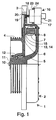
- Fig. 1 presents an elevator machinery 1 comprising an elevator motor 2 shown in a partly sectioned form, a brake 3, a traction sheave 4 and an emergency drive unit 16 as provided by the invention.
- the elevator motor 2 comprises a stator 5 and a rotor 6.
- the stator is a trough-shaped body of revolution with one side open, with a stator core packet 7 attached to it by means of fixing elements 8. Between the outer circles of the stator and rotor there is either a sliding seal or a labyrinth seal.
- the motor is fixed in place by the stator by means of fixing bolts 10.
- Bearings 12 are provided between the stator shaft 11 and the rotor 6.
- the rotor 6 is of a discoidal construction and its magnetization is implemented using e.g.
- the permanent magnets 14 mounted in a circle on the rotor surface. Between the permanent magnets 14 and the stator core packet 7 is a planar air gap 15, the plane of which is perpendicular to the stator shaft 11. The traction sheave 4 is attached to the rotor 6.
- the emergency drive unit 16 comprises a drive motor 17, a solenoid 21, and a power output of the motor, a gear wheel 18 and, attached to the rotor 6, a gear rim 19 by means of which the emergency drive unit 16 rotates the rotor 6.
- the gear rim 19 is placed on the inside of the brake rim 20.
- the drive motor 17 of the emergency drive unit 16 together with its auxiliary equipment is fixed to a flange 24 in the stator structure 5 by means of screws 23.
- the drive motor 17 with its auxiliary equipment is a starter motor, known in itself, as used for the starting of combustion engines, such as car engines, comprising the required motor, solenoid, switch and Bendix gear.
- the starter motors used in cars are generally direct-current series motors and are normally driven in one direction only.
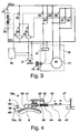
- Fig. 3 shows a diagram of a reversing circuit designed for use in an elevator drive.
- the operation of the emergency drive unit is as follows: Electric power is supplied to the drive motor 17 and solenoid 21, causing the gear wheel 18 to move onto the gear rim 19. At the same time, the brake 3 is released, with the result that the drive motor 17 begins to rotate the rotor and the elevator starts moving in a direction determined by the direction of rotation of the drive motor.
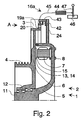
- Fig. 2 presents an alternative placement of the gear rim together with a manual drive latch.
- the gear rim 19a is now placed beside the brake rim 20.
- the traction sheave 4, brake rim 20 and gear rim 19a are preferably manufactured as an integrated structure with the rotor 6. It is naturally possible in the case of both Fig. 1 and Fig. 2 to manufacture the gear rim as a separate part which is then attached to the rotor.
- the gear rim is provided with wedge-shaped teeth (Fig. 4).
- the gear rim 19a is driven by a manual emergency drive unit 16a, which comprises a wedge-shaped latch 39 (Fig. 4), which is moved backwards and forwards by means of a manual lever 47.
- the power from the lever to the latch is transmitted by means of a flexible wire or wire cable 45 placed in a flexible tube 44.
- the emergency drive unit 16a is fixed to a flange 24 in the stator structure 5 by means of fixing elements 42, preferably screws.
- Fig. 3 presents the circuit diagram of an electric emergency drive unit 16 designed for bidirectional operation.
- the operating voltage DC+ and DC- for the emergency drive unit is obtained from a d.c. source 26, e.g. a 12 V battery, via a main switch 27.
- the negative terminal DC- is not connected to earth because the change of running direction of the drive motor is effected by changing the polarity by means of two contactors 31 and 32.
- Connected in series with the coils of the contactors is a contactor 28 for locking the elevator drive 25.
- pressing button 29 the elevator is driven upwards via contactor 31, and by pressing button 20, it is driven downwards via contactor 32.
- one contact 33 and 34 passes a current to the solenoid 21, which moves the gear wheel 18 into mesh with the gear rim 19 (Fig. 1-2).
- Starter motors usually have their own contact, which is not used in this circuit.
- the brake 3 is connected in parallel with the solenoid 21. In normal elevator operation, the brake receives its operating voltage through the elevator drive 25.
- the other two contacts, 35-36 and 37-38 form part of the reversing circuit, i.e. they change the polarity of the voltage supplied to the motor 17.
- Fig. 4 presents a manual emergency drive unit 16a as seen from direction A shown in Fig. 2.
- a gear rim 19a provided with wedge-shaped teeth.
- the gear rim is driven by a manual emergency drive unit 16a.
- the emergency drive unit comprises a wedge-shaped latch 39, which is moved back and forth by means of a manual lever 47.
- the power from the lever to the latch is transmitted by means of a flexible wire or wire cable 45 placed in a flexible tube 44, one end of the wire or cable being attached to the lever and the other to the latch 39.
- the emergency drive unit 16a is fixed to a flange 24 in the stator structure 5 by means of fixing elements 42.
- the lever 47 is pivoted on a base 46.
- the lever is turned back and forth in directions L and R, causing the wire 45 in the flexible tube 44 to move back and forth as well and therefore the latch to move with it.
- the latch is supported by a sleeve bearing 40 laid in the direction of the movement.
- the sleeve bearing 40 is pivoted on the frame 43 and provided with a spring 41.
- the brake 3 of the elevator is released when the lever is pulled in direction R, and when the lever is pushed in direction L, the brake is closed by means of a separate device, e.g. a separate wire/tube arrangement or a separate electric control signal to the brake to release it.
- the elevator is driven in this manner until it has reached the desired landing.
- the manual emergency drive unit 16a is provided with a shifter enabling the whole emergency drive unit to be shifted up so that the wedge-shaped latch 39 is completely out of contact with the gear rim 19a. However, this shifter is not shown in the figures.
- the manual emergency drive unit 16a can additionally be provided with an arrester 48 to prevent the rotor 6 from turning backwards while the lever is being pushed in direction L.
- the arrester 48 is mounted with a joint 49 on the stator 5.
- a spring 50 is mounted between the arrester 48 and the stator 5 to press the arrester against the gear rim 19a.
Landscapes
- Engineering & Computer Science (AREA)
- Civil Engineering (AREA)
- Mechanical Engineering (AREA)
- Structural Engineering (AREA)
- Maintenance And Inspection Apparatuses For Elevators (AREA)
- Cage And Drive Apparatuses For Elevators (AREA)
- Connection Of Motors, Electrical Generators, Mechanical Devices, And The Like (AREA)
Applications Claiming Priority (2)
| Application Number | Priority Date | Filing Date | Title |
|---|---|---|---|
| FI951430A FI98724C (fi) | 1995-03-24 | 1995-03-24 | Hissikoneiston hätäkäyttölaite |
| FI951430 | 1995-03-24 |
Publications (3)
| Publication Number | Publication Date |
|---|---|
| EP0733577A2 true EP0733577A2 (de) | 1996-09-25 |
| EP0733577A3 EP0733577A3 (de) | 1997-10-29 |
| EP0733577B1 EP0733577B1 (de) | 2003-09-24 |
Family
ID=8543125
Family Applications (1)
| Application Number | Title | Priority Date | Filing Date |
|---|---|---|---|
| EP96104740A Expired - Lifetime EP0733577B1 (de) | 1995-03-24 | 1996-03-25 | Notantriebseinheit für eine Aufzugsmaschine |
Country Status (7)
| Country | Link |
|---|---|
| EP (1) | EP0733577B1 (de) |
| KR (1) | KR100255463B1 (de) |
| CN (1) | CN1067960C (de) |
| DE (1) | DE69630066T2 (de) |
| ES (1) | ES2206526T3 (de) |
| FI (1) | FI98724C (de) |
| TW (1) | TW451938U (de) |
Cited By (8)
| Publication number | Priority date | Publication date | Assignee | Title |
|---|---|---|---|---|
| DE19815962A1 (de) * | 1998-04-09 | 1999-10-14 | Atb Antriebstechnik Ag | Elektrische Maschine, insbesondere für Fahrstuhlantrieb |
| FR2828876A1 (fr) * | 2001-08-23 | 2003-02-28 | Aficor Sa | Treuil motorise |
| AU758072B1 (en) * | 2001-07-11 | 2003-03-13 | Yung-Hsin Chen | Emergency moving device of an elevator |
| EP1338545A1 (de) * | 2002-02-18 | 2003-08-27 | Inventio Ag | Notantrieb für einen Aufzug |
| US6942067B2 (en) | 2002-02-18 | 2005-09-13 | Inventio Ag | Portable emergency drive for an elevator |
| WO2006074689A1 (en) * | 2005-01-11 | 2006-07-20 | Otis Elevator Company | Method for performing an elevator rescue run |
| EP1514825A4 (de) * | 2002-06-20 | 2008-12-10 | Mitsubishi Electric Corp | Hebewerk für aufzug |
| KR100903661B1 (ko) * | 2007-08-08 | 2009-06-18 | 오티스 엘리베이터 컴파니 | 엘리베이터 구조 작업을 수행하는 방법 |
Families Citing this family (5)
| Publication number | Priority date | Publication date | Assignee | Title |
|---|---|---|---|---|
| KR100441043B1 (ko) * | 2002-08-28 | 2004-07-19 | 현대엘리베이터주식회사 | 엘리베이터용 박형 권상기 |
| ES2246696B1 (es) | 2004-05-04 | 2006-11-16 | Orona, S. Coop. | Dispositivo de emergencia para elevacion o descenso de ascensores atrapados entre plantas. |
| BRPI0924643A2 (pt) | 2009-06-30 | 2016-03-08 | Otis Elevator Co | método para realizar uma ação de resgate de elevador,e, sistema de elevador. |
| JP5861252B2 (ja) * | 2010-12-09 | 2016-02-16 | 株式会社明電舎 | エレベータ巻上機の非常救出装置 |
| DE102013111278A1 (de) | 2013-10-11 | 2015-04-16 | Hans-Joachim Blocher | Verfahren zur Durchführung und Anordnung für einen Notbetrieb bei Aufzugsanlagen |
Family Cites Families (2)
| Publication number | Priority date | Publication date | Assignee | Title |
|---|---|---|---|---|
| FR2583029A1 (fr) * | 1985-06-07 | 1986-12-12 | Assignies Jean D | Perfectionnements aux dispositifs de securite pour une cage d'ascenseur ou analogue |
| FI93340C (fi) * | 1993-06-28 | 1995-03-27 | Kone Oy | Hissikoneisto |
-
1995
- 1995-03-24 FI FI951430A patent/FI98724C/fi active IP Right Grant
-
1996
- 1996-03-20 TW TW088211490U patent/TW451938U/zh not_active IP Right Cessation
- 1996-03-21 KR KR1019960007661A patent/KR100255463B1/ko not_active Expired - Fee Related
- 1996-03-24 CN CN96104336A patent/CN1067960C/zh not_active Expired - Lifetime
- 1996-03-25 EP EP96104740A patent/EP0733577B1/de not_active Expired - Lifetime
- 1996-03-25 ES ES96104740T patent/ES2206526T3/es not_active Expired - Lifetime
- 1996-03-25 DE DE69630066T patent/DE69630066T2/de not_active Expired - Fee Related
Cited By (10)
| Publication number | Priority date | Publication date | Assignee | Title |
|---|---|---|---|---|
| DE19815962A1 (de) * | 1998-04-09 | 1999-10-14 | Atb Antriebstechnik Ag | Elektrische Maschine, insbesondere für Fahrstuhlantrieb |
| EP0949743A3 (de) * | 1998-04-09 | 2000-07-19 | ATB Antriebstechnik AG | Elektrische Maschine, insbesondere für Fahrstuhlantrieb |
| AU758072B1 (en) * | 2001-07-11 | 2003-03-13 | Yung-Hsin Chen | Emergency moving device of an elevator |
| FR2828876A1 (fr) * | 2001-08-23 | 2003-02-28 | Aficor Sa | Treuil motorise |
| WO2003018461A1 (fr) * | 2001-08-23 | 2003-03-06 | Aficor S.A. | Treuil motorise |
| EP1338545A1 (de) * | 2002-02-18 | 2003-08-27 | Inventio Ag | Notantrieb für einen Aufzug |
| US6942067B2 (en) | 2002-02-18 | 2005-09-13 | Inventio Ag | Portable emergency drive for an elevator |
| EP1514825A4 (de) * | 2002-06-20 | 2008-12-10 | Mitsubishi Electric Corp | Hebewerk für aufzug |
| WO2006074689A1 (en) * | 2005-01-11 | 2006-07-20 | Otis Elevator Company | Method for performing an elevator rescue run |
| KR100903661B1 (ko) * | 2007-08-08 | 2009-06-18 | 오티스 엘리베이터 컴파니 | 엘리베이터 구조 작업을 수행하는 방법 |
Also Published As
| Publication number | Publication date |
|---|---|
| ES2206526T3 (es) | 2004-05-16 |
| FI951430A0 (fi) | 1995-03-24 |
| CN1135451A (zh) | 1996-11-13 |
| KR960034055A (ko) | 1996-10-22 |
| KR100255463B1 (ko) | 2000-05-01 |
| FI951430L (fi) | 1996-09-25 |
| FI98724B (fi) | 1997-04-30 |
| EP0733577A3 (de) | 1997-10-29 |
| CN1067960C (zh) | 2001-07-04 |
| DE69630066D1 (de) | 2003-10-30 |
| DE69630066T2 (de) | 2004-04-01 |
| TW451938U (en) | 2001-08-21 |
| EP0733577B1 (de) | 2003-09-24 |
| FI98724C (fi) | 1997-08-11 |
Similar Documents
| Publication | Publication Date | Title |
|---|---|---|
| EP0733577B1 (de) | Notantriebseinheit für eine Aufzugsmaschine | |
| JP2990058B2 (ja) | エレベータ運転用同期モータの緊急操作装置 | |
| EP1564880A1 (de) | Fahrzeug mit Bergabfahrtsregelung | |
| US2193683A (en) | Drive mechanism | |
| KR860003715Y1 (ko) | 엘리베이터용 권상기 | |
| US844661A (en) | Clutch-controlled elevator. | |
| JP2002525003A5 (de) | ||
| JP2003134613A (ja) | 動力伝達装置、自動車、自転車及び一方向クラッチ付きモータの制御方法 | |
| JPS63206103A (ja) | 車両用リターダ | |
| JP2000211882A (ja) | クレ―ンの駆動モ―タ停止制御方法 | |
| JPS6113663Y2 (de) | ||
| JP3700774B2 (ja) | 動力伝達装置、自動車、自転車及び摩擦ローラ式変速機付きモータの制御方法 | |
| JP2002525003A (ja) | 電動機を有する装置に対する緊急動作装置 | |
| JP4378935B2 (ja) | 電動機の制御装置 | |
| JPH0710402A (ja) | 昇降機用駆動装置の制御方法及びそれに用いる駆動装置 | |
| JP3752079B2 (ja) | 機械の緊急停止回路 | |
| JPS6337296Y2 (de) | ||
| SU1237592A1 (ru) | Способ управлени торможением шахтного подъемника с двухдвигательным асинхронным электроприводом | |
| CN119317584A (zh) | 电梯的安全钳装置、电梯和电梯的安全钳装置的操作方法 | |
| JP2511066Y2 (ja) | 電動機の駆動電源回路 | |
| SU981196A1 (ru) | Устройство дл управлени лебедкой | |
| JPH089302B2 (ja) | 車両の動力装置 | |
| JP3375285B2 (ja) | 電動モータおよびエンジン駆動機械の始動・停止回路 | |
| JPS61127588A (ja) | エレベ−タ−の駆動装置 | |
| JPS6141745Y2 (de) |
Legal Events
| Date | Code | Title | Description |
|---|---|---|---|
| PUAI | Public reference made under article 153(3) epc to a published international application that has entered the european phase |
Free format text: ORIGINAL CODE: 0009012 |
|
| AK | Designated contracting states |
Kind code of ref document: A2 Designated state(s): DE ES FR GB IT |
|
| PUAL | Search report despatched |
Free format text: ORIGINAL CODE: 0009013 |
|
| AK | Designated contracting states |
Kind code of ref document: A3 Designated state(s): DE ES FR GB IT |
|
| 17P | Request for examination filed |
Effective date: 19980328 |
|
| RAP1 | Party data changed (applicant data changed or rights of an application transferred) |
Owner name: KONE CORPORATION |
|
| 17Q | First examination report despatched |
Effective date: 20010702 |
|
| GRAH | Despatch of communication of intention to grant a patent |
Free format text: ORIGINAL CODE: EPIDOS IGRA |
|
| GRAS | Grant fee paid |
Free format text: ORIGINAL CODE: EPIDOSNIGR3 |
|
| GRAA | (expected) grant |
Free format text: ORIGINAL CODE: 0009210 |
|
| AK | Designated contracting states |
Kind code of ref document: B1 Designated state(s): DE ES FR GB IT |
|
| REG | Reference to a national code |
Ref country code: GB Ref legal event code: FG4D |
|
| REF | Corresponds to: |
Ref document number: 69630066 Country of ref document: DE Date of ref document: 20031030 Kind code of ref document: P |
|
| REG | Reference to a national code |
Ref country code: ES Ref legal event code: FG2A Ref document number: 2206526 Country of ref document: ES Kind code of ref document: T3 |
|
| ET | Fr: translation filed | ||
| PLBE | No opposition filed within time limit |
Free format text: ORIGINAL CODE: 0009261 |
|
| STAA | Information on the status of an ep patent application or granted ep patent |
Free format text: STATUS: NO OPPOSITION FILED WITHIN TIME LIMIT |
|
| 26N | No opposition filed |
Effective date: 20040625 |
|
| PGFP | Annual fee paid to national office [announced via postgrant information from national office to epo] |
Ref country code: ES Payment date: 20080325 Year of fee payment: 13 |
|
| PGFP | Annual fee paid to national office [announced via postgrant information from national office to epo] |
Ref country code: GB Payment date: 20080228 Year of fee payment: 13 |
|
| PGFP | Annual fee paid to national office [announced via postgrant information from national office to epo] |
Ref country code: DE Payment date: 20080227 Year of fee payment: 13 |
|
| GBPC | Gb: european patent ceased through non-payment of renewal fee |
Effective date: 20090325 |
|
| PG25 | Lapsed in a contracting state [announced via postgrant information from national office to epo] |
Ref country code: DE Free format text: LAPSE BECAUSE OF NON-PAYMENT OF DUE FEES Effective date: 20091001 |
|
| PG25 | Lapsed in a contracting state [announced via postgrant information from national office to epo] |
Ref country code: GB Free format text: LAPSE BECAUSE OF NON-PAYMENT OF DUE FEES Effective date: 20090325 |
|
| REG | Reference to a national code |
Ref country code: ES Ref legal event code: FD2A Effective date: 20090326 |
|
| PG25 | Lapsed in a contracting state [announced via postgrant information from national office to epo] |
Ref country code: ES Free format text: LAPSE BECAUSE OF NON-PAYMENT OF DUE FEES Effective date: 20090326 |
|
| PGFP | Annual fee paid to national office [announced via postgrant information from national office to epo] |
Ref country code: FR Payment date: 20130408 Year of fee payment: 18 |
|
| PGFP | Annual fee paid to national office [announced via postgrant information from national office to epo] |
Ref country code: IT Payment date: 20130327 Year of fee payment: 18 |
|
| REG | Reference to a national code |
Ref country code: FR Ref legal event code: ST Effective date: 20141128 |
|
| PG25 | Lapsed in a contracting state [announced via postgrant information from national office to epo] |
Ref country code: FR Free format text: LAPSE BECAUSE OF NON-PAYMENT OF DUE FEES Effective date: 20140331 |
|
| PG25 | Lapsed in a contracting state [announced via postgrant information from national office to epo] |
Ref country code: IT Free format text: LAPSE BECAUSE OF NON-PAYMENT OF DUE FEES Effective date: 20140325 |