EP0733580A2 - Train de roulement avec amortissement des oscillations pendulaires - Google Patents
Train de roulement avec amortissement des oscillations pendulaires Download PDFInfo
- Publication number
- EP0733580A2 EP0733580A2 EP96103256A EP96103256A EP0733580A2 EP 0733580 A2 EP0733580 A2 EP 0733580A2 EP 96103256 A EP96103256 A EP 96103256A EP 96103256 A EP96103256 A EP 96103256A EP 0733580 A2 EP0733580 A2 EP 0733580A2
- Authority
- EP
- European Patent Office
- Prior art keywords
- speed
- electric drive
- drive according
- state
- electronic control
- Prior art date
- Legal status (The legal status is an assumption and is not a legal conclusion. Google has not performed a legal analysis and makes no representation as to the accuracy of the status listed.)
- Withdrawn
Links
Images


Classifications
-
- B—PERFORMING OPERATIONS; TRANSPORTING
- B66—HOISTING; LIFTING; HAULING
- B66C—CRANES; LOAD-ENGAGING ELEMENTS OR DEVICES FOR CRANES, CAPSTANS, WINCHES, OR TACKLES
- B66C13/00—Other constructional features or details
- B66C13/04—Auxiliary devices for controlling movements of suspended loads, or preventing cable slack
- B66C13/06—Auxiliary devices for controlling movements of suspended loads, or preventing cable slack for minimising or preventing longitudinal or transverse swinging of loads
- B66C13/063—Auxiliary devices for controlling movements of suspended loads, or preventing cable slack for minimising or preventing longitudinal or transverse swinging of loads electrical
-
- B—PERFORMING OPERATIONS; TRANSPORTING
- B66—HOISTING; LIFTING; HAULING
- B66C—CRANES; LOAD-ENGAGING ELEMENTS OR DEVICES FOR CRANES, CAPSTANS, WINCHES, OR TACKLES
- B66C13/00—Other constructional features or details
- B66C13/18—Control systems or devices
- B66C13/22—Control systems or devices for electric drives
- B66C13/30—Circuits for braking, traversing, or slewing motors
Definitions
- the chassis equipped with an asynchronous motor accelerates quickly and changes to a constant driving speed after a short driving distance.
- the consequence of the jerky acceleration of the undercarriage is that the load hanging on the extended chain begins to oscillate and the oscillation does not stop even when the undercarriage is moving at a constant speed moved on.
- the movement of the load can be broken down into two components, namely a uniform movement in the direction of travel and an oscillating movement which tends to alternately decelerate or accelerate the undercarriage. Because of the hard characteristic of the asynchronous motor, the undercarriage cannot follow this force induced by the pendulum motion, which is why the undercarriage acts like a rigid, fixed suspension for the pendulum motion component.
- the undercarriage can follow the pendulum movement because when the load swings forward, the undercarriage can follow the load.
- the undercarriage is accelerated by the motor when the hook load is at rest, the undercarriage has already moved a considerable distance from the rest position before the load hanging on the hook is accelerated in the direction of travel. If a jerky acceleration occurs from standstill, a load oscillation is induced by the jerky acceleration. As a result of the load oscillation, the load will endeavor to run ahead of the chassis after a certain travel distance of the chassis, i.e. the swinging load in turn pulls the undercarriage and tries to accelerate it. In contrast to simple asynchronous motors, the chassis equipped with the new drive system can follow this acceleration caused by the load swinging. In this way, the energy contained in the oscillating load is converted into driving energy that keeps the running gear moving.
- Such a drive characteristic can be achieved either by means of an asynchronous motor with freewheeling or with the aid of a motor with a main closing characteristic. This is because the motor with the main fault characteristic cannot act as a brake, because there is no speed at which a generator effect can occur as long as the polarity between the armature and the field winding is not changed.
- the universal motor working in the main circuit has a very soft speed-torque characteristic.
- the load oscillation is reduced in any case in a chassis with a regulated universal motor as the drive, because this type of drive reduces jerky accelerations.
- the flexibility of the travel drive can be further increased if the switch arrangement has at least a third switching state in which the power supply to the motor is possible. Either a further rigid driving speed or the "accelerate" operating state can be assigned to this third switching state.
- the undercarriage can then be operated at least with two different speeds of a fixed size or else with a stepless speed setting that can be increased up to a maximum speed.
- the direction of travel can also be reversed with any type of motor if the running gear is to be bidirectional.
- the switch arrangement is equipped with either only one or with two further switch positions, so that the same possibilities with regard to the driving speed are available in every direction of travel.
- the switch arrangement can be operated remotely from a higher-level process control, for example when the hoist is running in a largely automated system, or there is the possibility of transferring the switch arrangement into the different switching positions via a manually operated actuator. In the latter case, it is a push button switch arrangement, as is usually used in control bulbs of hoists.
- the undercarriage or the motor has a speed sensor that is connected to the electronic control system and that transmits a signal proportional to the vehicle speed to the electronic control system.
- phase control can also be viewed as a kind of pulse width modulation with a fixed clock frequency, which is predetermined by the network frequency.
- the regulation of the motor speed in a motor with a main closing characteristic can be carried out either with the aid of a proportional regulator or with the aid of an integral regulator.
- the latter has the main advantage that no residual error remains when the leveling is corrected.
- controller can be constructed at any time using discrete physical components, it is expedient to implement the controller on the basis of a microprocessor, which means that the controller itself works incrementally.
- control characteristics can be generated that are difficult or impossible to implement with discrete components.
- certain unpleasant properties of integral controllers such as slow response or starting with the wrong initial value, can be easily eliminated.
- an initial value is assigned to the controller, which inevitably comes into effect when the undercarriage is started from a standstill.
- This initial value does not necessarily have to be identical to the steps by which the value of the controller or the state of the controller is incremented if, after the first switching on of the operation, the desired control in the sense of keeping the speed constant or reaching a desired speed is activated is.
- the current flow angle Since usually the current flow angle becomes larger faster than the undercarriage can accelerate, the current flow angle will be larger when it reaches the nominal speed than is necessary to keep this speed reached constant.
- the state of the controller after the first exceeding of the set speed is expediently reduced by a value which in turn is expediently greater than the incremental value with which the controller otherwise works in normal operation.
- the controller works with different or larger jumps than in normal operation, if one Operational situation change occurs, which is ultimately caused by a change in the switch position.
- a setpoint generator is used, which can assume different values depending on the switch position.
- the setpoint generator In the case of acceleration from standstill or an existing driving speed, the setpoint generator is set to a value that corresponds to the maximum possible or a higher speed.
- the value of the setpoint generator is converted to the current speed value, so that the controller can orientate itself from this setpoint until the next adjustment is arranged becomes.
- a delay i.e. the decrease in driving speed towards a lower speed.
- Fig. 1 shows a schematic representation of a mechanical embodiment of a drive system for the carriage of a hoist, for example a trolley, as used in floor-free conveyors.
- the drive system has an asynchronous motor 1 which only runs in one direction, the output shaft 2 of which is mechanically coupled to a schematically illustrated freewheel 3.
- the freewheel 3 On the output side, the freewheel 3 is connected to an input shaft 4 of a reduction gear 5, the output shaft 6 of which is in turn non-rotatably coupled to one of the drive wheels 7.
- the drive wheel 7 runs on a schematically shown rail 8.
- a control switch not shown, is used to ensure that the drive motor 1 is supplied with electrical energy, it begins to rotate, specifically with the design direction of rotation. He drives the input shaft 4 of the transmission 5 via the freewheel 3, which in this direction is non-positively coupled, and which then sets the drive wheel 7 in motion.
- the chassis is accelerated relatively abruptly. This strong acceleration cannot be followed by the load hanging on the load suspension device in the form of a rope or a chain, which is why it will initially lag behind the running gear.
- the asynchronous motor 1 After a time dependent on the conditions, the asynchronous motor 1 reaches its nominal speed, which means that from now on the running gear will travel along the running rail 8 at a constant speed.
- the load initially lagging the movement of the undercarriage forms a pendulum under the undercarriage traveling at constant speed, which is deflected by the jerky approach movement and which swings with its own time constant, that of the extended length of the load handler and the mass of the attached load.
- the load oscillating in the driving direction will catch up with the running gear, in the sense that the load is located directly under the running gear.
- the oscillating load has exerted a decelerating force on the chassis. Starting from the moment the load is under the chassis and from now on, as the load overtakes the chassis in the sense of hurrying ahead, the load will exert a tractive force on the chassis that tends to accelerate the chassis.
- the asychnron motor 1 cannot follow this acceleration because it can accelerate at most up to the synchronous speed, which in practical operation is only a few percent below the load speed that occurs when driving the undercarriage.
- the freewheel 7 disengages in this operating situation and thus makes it possible to follow the chassis of the load swinging forward.
- the load swinging forward will feed part of its pendulum energy into the chassis as propulsion energy.
- the result is that the pendulum formed by the load at the turning point is not as far from the zero position in which the load would be located directly under the chassis as would be the case if the drive train between the wheel 7 and the engine 1 would not have disengaged.
- the undercarriage that has been pulled by the load has absorbed part of the pendulum energy.
- the entire pendulum energy can be damped out in a few pendulum cycles without the need for control measures.
- the pendulum damping takes place during the forward swing, ie the half of the oscillation in which the load strives to lead the undercarriage because during this half-wave the pendulum energy is converted into driving energy for the undercarriage.
- the motor 1 itself does not deliver any propulsion energy during this phase. Since the pendulum must always swing symmetrically to the zero position (it cannot always be at an angle in space), the amplitude in the backswing is at most as large as the amplitude in the last forward swing.
- FIG. 1 The purely mechanical solution shown in FIG. 1 is preferably suitable for monorail overhead conveyors in which the trolleys always run in the same direction along a closed path. If a reversal of the direction of rotation is required, the freewheel 3 would have to be reversed in its direction of action in accordance with the direction of travel and in such a way that a force acting on the chassis in the direction of travel must be able to actually accelerate the chassis while uncoupling from the motor 1.
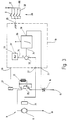
- the drive motor in the embodiment according to FIG. 2 is a universal motor 9 working in the main closing operation, consisting of an armature 11 and an associated field winding 12.
- the armature 11 is connected to a phase conductor 13 of an AC network with a connecting terminal, while another connection of the armature 11 to a End of the field winding 12 is connected.
- the other end of the Field winding is connected to another phase conductor 15 or a neutral conductor of the AC network via a triac 14.
- the armature 11 drives an input shaft 16 of a reduction gear 17, the output shaft 18 of which is in turn non-rotatably connected to the drive wheel 7 of the undercarriage.
- the triac 14 is controlled by means of an electronic control device 19, the output 21 of which delivers trigger pulses to the gate of the triac 14.
- the controller 19 has an input 22 which is connected to a speed sensor 24 via a connecting line 23.
- the speed sensor 24 is rotatably coupled to the armature 11.
- the control 19 is actuated by a schematically indicated switch arrangement 26 connected to an input 25.
- This switch arrangement 26 can optionally be a manually operated push-button arrangement or they can also represent signals that come from a higher-level control and actuate or control the control 19. For the sake of simplicity, it is assumed that these are hand switches that are operated by the user of the lifting device in question.
- the controller 19 In the neutral or zero position, the controller 19 does not emit any trigger pulses to the triac 14, which is why the circuit leading through the motor 9 remains interrupted.
- the controller 19 thereby receives a corresponding signal and at its input 25 from then on it supplies trigger pulses synchronized with the AC voltage of the network to the gate of the triac 14 in a known manner.
- each first firing pulse for the triac 14 it goes into the conductive state and remains conductive until the AC mains voltage and, associated with it, the current through the universal motor 9 disappears.
- the triac 14 extinguishes at this point in time and remains blocked during the next half-wave until it receives a renewed ignition pulse from the controller 19 at its gate.
- the relative position of the ignition pulses in relation to the preceding zeros of the AC mains voltage determines what power the universal motor 9 can draw from the network.
- the controller 19 acts as a controller and regulates the phase gating or ignition angle in the sense of stabilizing the speed of the universal motor 9, for which purpose it detects its armature speed via the speed sensor 24.
- the controller 19 is thus, in the broadest sense, a controller which, with a corresponding signal at its input 25, adjusts the electrical power supplied to the universal motor 9 in such a way that the universal motor 9 runs at a predetermined speed.
- the phase angle for the universal motor 9 becomes small and, consequently, the current flow angle becomes large when the motor is loaded and its speed threatens to decrease or, conversely, the phase angle becomes large and thus the current flow angle becomes small when the speed of the universal motor 9 wants to rise because of acceleration or relief.
- the assumed user has brought the push button switch 26 into the driving position when the running gear is stationary. Since the controller 19 receives the speed zero from the sensor 24, it will initially operate the triac 14 with a very small phase angle, so that the universal motor 9 can draw a lot of electrical power from the network to accelerate the chassis. To the extent that its speed approaches the target speed, the controller 19 begins to increase the phase angle, which leads to a reduction in the power consumption from the network until the nominal speed is reached.
- the load will lag the chassis due to the start-up process, i.e. the pendulum formed by the load is deflected against the direction of travel.
- the universal motor 9 has reached its nominal speed, which is adjusted with the aid of the control 19, the further acceleration of the oscillating load stops.
- the pendulum vibration will now take place in the direction of travel.
- the pendulum formed by the load has exceeded its zero position, at which the load is located directly vertically under the chassis or, in other words, the load handler is aligned parallel to the gravity vector, and begins to run ahead of the chassis in the direction of travel, the load is aimed to pull the landing gear behind you.
- the electrical properties of the universal motor 9 working in the main closing operation in connection with the control 19 now act as in the embodiment according to FIG. 1 of the freewheel 3 in that they enable the undercarriage to be driven by the load.
- the leading load wants to pull the chassis and thus leads to an output-side relief of the motor 9, which consequently has to deliver less drive energy.
- the main tail motor cannot act as such a brake, the load swinging forward in the direction of travel, overtaking the undercarriage, is able to drag the undercarriage behind it, thereby reducing the amplitude directed towards the front.
- forward-looking amplitude is to be understood as the maximum deflection in the reversal point relative to the zero position. In the zero position, the load is located directly under the chassis and the load suspension device, i.e. the rope or chain, runs parallel to the gravity vector.
- a major advantage of the arrangement according to FIG. 2 is that no mechanical freewheel is required, but that relatively cheap and space-saving electronic components are used to emulate the freewheeling characteristic.
- the distances that a trolley must travel during its life are not so large that the commutator present in a universal motor and its life would be an impairment.
- the direction of rotation of the universal motor can be changed at any time, which makes journeys in both directions possible.
- the field winding 12 is electrically connected to the armature 11 in a known manner via a pole reversing device, as shown in FIG. 3, in order to change the direction of rotation of the universal motor 9.
- the undercarriage can optionally be started in both directions, the pendulum-damping properties of the new drive concept being effective in both directions.
- an essential advantage of the arrangement according to FIG. 2 is that undercarriages with several speeds or also stepless speed setting can be realized in a comparatively simple manner, as will be explained below.
- the controller 19 is a microprocessor which is able to deliver the desired mains-synchronized ignition pulses at its output 21 to the triac 14 and which is also connected via its input 25 to a switch set.
- this switch set has a neutral or zero position, a first switch position, which corresponds to a creep speed, and a second switch position, which corresponds to the rapid speed, the chassis running in the same direction in both switch positions.
- FIG. 3 shows the associated basic circuit diagram, namely that switch positions I to IV are each assigned a separate switch set, while the zero or neutral position corresponds to an operating situation in which all switches are open at the same time.
- the field winding 12 is located in the series circuit consisting of the armature 11 and the triac 14 via a reversing switch 28 actuated by a relay winding 27. which are not included for the sake of simplicity, since they are not important for understanding the invention.
- the switches corresponding to the individual switching states which are designated I to IV, are connected to the input 25, which has four individual lines which are separate from one another. They should represent the different signal states at the input, whereby the above assignment applies.
- These switches I to IV are connected at one end to a positive DC supply voltage U.
- the controller 19 has a further output 29, via which the relay winding 27 is controlled, so that the direction of rotation of the universal motor 9 can be changed.
- a PI controller 31 With the help of the microprocessor implementing the controller 19, a PI controller 31, a setpoint / actual value comparator 32 and a switchable reference 33 are implemented.
- One input of the target / actual value comparator 32 is connected to the input 22, while the other input is connected to an output 34 of the reference.
- the output signal obtained from the comparator 32 reaches an input 35 of the PI controller 31, which is at an input 36 as well as the reference at its input 37 is controlled via signals coming from the input 25.
- the PI controller 31 finally has an output 38, which is connected to the output 21 of the controller 19.
- FIG. 5 shows the flowchart which illustrates that section of the overall program of the microprocessor which is implemented for the desired control of the motor 9.
- the flow chart shown in FIG. 4 is not followed. It is only when one of the switches I to IV is actuated or a corresponding control signal is supplied that the microprocessor starts a program corresponding to the flow chart in FIG. 4.
- the program begins at 41 and asks at a program point 42 which switch I to IV is actuated. This actuation state is stored and the program then continues in order to query the input 22 at 43, at which a signal characterizing the speed of the universal motor 9 is delivered by the speed sensor 24.
- the actual speed v ist is stored and the program continues to the program point 44, at which a reference speed is generated, with which the actual speed is compared.
- this ramp generator for guiding the actual speed are the operated switch and the time that has elapsed since the switch was operated. For the further description it is assumed that the switch I a normal speed in the forward direction, the switch II a rapid speed in the forward direction, the Switch III a normal speed in the reverse direction and the switch IV the rapid speed in the reverse direction are assigned.
- the ramp generator gradually runs up to a speed corresponding to normal speed or to a speed corresponding to rapid speed during several program runs.
- a query is made at the branching point 45 as to whether the state at the input 25 has changed at this point since the last run or whether the switch position has been changed or whether the reference value has been changed for the first time after a previous switch change V is said to have been exceeded.
- the program then continues at an instruction block 48.
- the program calculates the difference between the reference value v soll and the actual speed v ist and obtains a control deviation parameter p from this.
- This calculation branches at 49, depending on whether the system deviation parameter p is greater than zero or not. If the control deviation parameter p is greater than zero, this means that the actual speed is still lower than the target speed or the electrical power supplied to the universal motor 9 is not yet sufficient to bring the travel drive to the desired speed. Therefore, the current flow angle ⁇ is increased by a ⁇ in an instruction block 51 and stored again.
- the incremental value ⁇ itself can be its function of the control deviation parameter p or else constant.
- the controller 31 acts as a PI controller, a proportional component must also be added to the current flow angle ⁇ , which represents the integral component.
- the actual current flow angle ⁇ is obtained from this by adding the control deviation parameter p or a variable derived from it to the integral component ⁇ of the current flow angle.
- the current flow angle ⁇ is converted at 52 into the point in time at which, based on the preceding zero of the mains AC voltage, the ignition pulse for the triac 14 must be delivered in order to get the desired current flow angle.
- the program then returns to block 42 and checks whether the position of switches I to IV has changed in the meantime. Suppose there was no change observed, the state stored on the switch operation is retained and the program can again at 43 the actual speed v query and update the corresponding memory variable.
- the parameter for the desired speed v soll is increased in time up to the value that corresponds to the switch actuation I or II or III or IV in question, the value of the command variable v soll increases gradually during successive runs.
- the switch operation had not been changed and also there is the landing gear is still in the acceleration phase, ie v is smaller than the predetermined switch operation by the target speed.
- the program will therefore continue directly through the block 48 and in block 51 the integral component ⁇ incremental increase of the flow angle, while on the other hand, the deviation parameter p becomes gradually smaller, because the difference between V and V should be reduced accordingly.
- the point in time will come at which the ramp generation will provide a reference value v soll which is equal to the target speed at which the undercarriage is to travel in accordance with switch actuation I. From then on, the ramp generator at 44 provides a constant reference value v soll long change until the switch positions at the entrance 25th
- the integral component of the current flow angle ⁇ is abruptly reduced by a larger amount than ⁇ by subtracting a fixed quantity K 1 from the integral component of the current flow angle ⁇ .
- the integral component of the current flow angle ⁇ becomes incremental reduced by ⁇ , which in turn can be a function of p or has a constant value.
- the integral component ⁇ is reduced by the amount of the control deviation parameter p or a quantity derived therefrom in order to obtain the actual current flow angle ⁇ , which is then converted again at the program point 52 into the correspondingly distorted ignition pulse.
- the free-wheeling characteristic mentioned at the outset is realized by the fact that the set speed is exceeded during the swinging of the load and thus during the towing of the chassis by the swinging load, which leads to the PI controller running via the instruction block 55 and increasingly reducing the integral component ⁇ .
- the current flow angle becomes correspondingly smaller, i.e. the propulsion energy for the chassis comes from the pulling load.
- a variant is the actuation of switch II, ie starting and then accelerating up to the rapid speed. This measure is essentially only noticeable in the area of the setpoint generator at 44, insofar as the reference parameter V soll is increased there up to the target speed corresponding to the rapid speed. Otherwise, the program behaves as previously described, because it starts at the first start, starting from state zero, as before via branch point 46 and instruction block 47.
- the next variant that has to be taken into account is the actuation of switch II after switch I has already been actuated and the undercarriage is traveling at normal speed. This corresponds to an acceleration from normal speed to rapid speed.
- the program runs at the first run after actuation of switch II following branch 45 to a branch point 56, to which an instruction block 57 follows, where the integral component ⁇ jumps by a constant K 2 is increased.
- the program then behaves as described at the beginning.
- the last variant to be observed consists in switching back from switch position II to switch position I, i.e. slowing the driving speed from the rapid speed to the normal speed.
- the program goes at branching point 45 in the left branch according to FIG. 4 to a branching point 58, in which it is checked whether the actual speed is greater than the target speed, which is usually always the case when switching back , whereupon an instruction block 59 returns to the normal part of the program to instruction block 48.
- the integral component ⁇ is set to a new initial value ⁇ S2 , which is smaller than that corresponding to driving at normal speed.
- switch position I or switch position III corresponds to a state in which the undercarriage should continue to travel at the travel speed reached at the switchover time.
- Switch position II and, accordingly, switch position IV mean starting or accelerating the vehicle as long as this switch state is maintained or a maximum permissible driving speed has not yet been exceeded.
- this behavior at block 44 corresponds approximately to the behavior of block 44 according to FIG. 4.
- the program branches at query point 45 into the left part to an query point 61, which essentially corresponds to query point 46 according to FIG. 4. If the condition forming the criterion there is met, the integral component ⁇ of the current flow angle is set to a start value ⁇ s1 and the program continues with the instruction block 48, from where it behaves exactly as explained in connection with FIG. 4 .
- the changeover from state II to state I is again recognized at branching point 45, whereby the program in turn branches into the left branch and runs to query point 63.
- the program causes the integral component ⁇ to be abruptly reduced by a constant K 2 , because during the preceding acceleration phase the current flow angle has reached values which are greater than are required for driving at the constant speed.
- the controller swings in faster.
- the program according to FIG. 5 then behaves in exactly the same way as the program according to FIG. 4 when the reference speed is exceeded.
- a travel drive for a trolley of hoists has a drive train that shows a free-wheeling characteristic with respect to the direction of travel. This has the consequence that a load oscillation can be damped out quickly, because during the half oscillation of the load oscillation, in which the load leads the running gear, the running gear is not kept constant. Rather, the oscillating load is able to accelerate the chassis behind it and in this way convert pendulum energy into driving energy.
Landscapes
- Engineering & Computer Science (AREA)
- Mechanical Engineering (AREA)
- Automation & Control Theory (AREA)
- Control Of Electric Motors In General (AREA)
- Control And Safety Of Cranes (AREA)
- Electric Propulsion And Braking For Vehicles (AREA)
Applications Claiming Priority (2)
| Application Number | Priority Date | Filing Date | Title |
|---|---|---|---|
| DE19510167A DE19510167C2 (de) | 1995-03-21 | 1995-03-21 | Fahrwerk mit Pendeldämpfung |
| DE19510167 | 1995-03-21 |
Publications (2)
| Publication Number | Publication Date |
|---|---|
| EP0733580A2 true EP0733580A2 (fr) | 1996-09-25 |
| EP0733580A3 EP0733580A3 (fr) | 1997-11-26 |
Family
ID=7757238
Family Applications (1)
| Application Number | Title | Priority Date | Filing Date |
|---|---|---|---|
| EP96103256A Withdrawn EP0733580A3 (fr) | 1995-03-21 | 1996-03-02 | Train de roulement avec amortissement des oscillations pendulaires |
Country Status (4)
| Country | Link |
|---|---|
| US (1) | US5811945A (fr) |
| EP (1) | EP0733580A3 (fr) |
| JP (1) | JPH08268683A (fr) |
| DE (1) | DE19510167C2 (fr) |
Families Citing this family (11)
| Publication number | Priority date | Publication date | Assignee | Title |
|---|---|---|---|---|
| WO1999027642A1 (fr) * | 1997-11-25 | 1999-06-03 | Hans Hermann Rottmerhusen | Commande pour moteur a collecteur |
| DE19911429A1 (de) * | 1999-03-05 | 2000-09-07 | Mannesmann Ag | Verfahren und Steuerschaltung zum Anhalten eines mit Gleich- und/oder Wechselstrom betreibbaren Elektromotors, insbesondere von Hebezeugen |
| AU2001289294A1 (en) | 2000-03-30 | 2001-10-15 | Delware Capital formation | Variable reluctance motor with improved tooth geometry |
| US20030038556A1 (en) * | 2000-03-30 | 2003-02-27 | Gieskes Koenraad Alexander | Variable reluctance motor |
| US6759822B2 (en) * | 2001-12-20 | 2004-07-06 | Southern Illinois University | Methods and apparatus to improve the performance of universal electric motors |
| DE102004021374B4 (de) * | 2004-04-30 | 2023-09-21 | Robert Bosch Gmbh | Traktionsregler mit Vorsteuereinrichtung |
| CN2770726Y (zh) * | 2004-10-12 | 2006-04-12 | 王国华 | 调速电动高尔夫球具袋车 |
| DE102012205728A1 (de) * | 2012-04-05 | 2013-10-10 | Robert Bosch Gmbh | Verfahren und Vorrichtung zum elektrodynamischen Bremsen eines Universalmotors |
| DE102015002864B4 (de) * | 2015-03-06 | 2020-03-19 | Sew-Eurodrive Gmbh & Co Kg | System mit mittels einem oder mehreren Fahrantrieben verfahrbarem Hubwerk und Verfahren zum Betreiben des Systems |
| CN113342169B (zh) * | 2021-06-10 | 2023-03-17 | 中国水利水电第七工程局有限公司 | 一种基于力反馈的塔式起重机操作虚拟培训系统 |
| US20250368325A1 (en) * | 2024-06-03 | 2025-12-04 | Rockwell Collins, Inc. | Hoisting flight director mode |
Family Cites Families (20)
| Publication number | Priority date | Publication date | Assignee | Title |
|---|---|---|---|---|
| DE591809C (de) * | 1930-12-04 | 1934-01-27 | Aeg | Schaltung fuer Fahrbetriebe |
| GB1132967A (en) * | 1964-12-08 | 1968-11-06 | Davy And United Instr Ltd | Control systems for preventing swinging of suspended loads |
| DE1923887A1 (de) * | 1968-05-10 | 1969-11-20 | English Electric Co Ltd | Elektromotor-Steuersystem fuer Krane |
| DE2022745C3 (de) * | 1970-05-09 | 1979-07-19 | Siemens Ag, 1000 Berlin Und 8000 Muenchen | Anordnung zur Unterdrückung von Pendelschwingungen einer an einem Seil hängenden, von einer Laufkatze beförderten Last |
| US3965404A (en) * | 1973-08-17 | 1976-06-22 | Cordem Corporation | Apparatus and method of braking a universal motor for operating a compact winch |
| LU77931A1 (fr) * | 1977-08-05 | 1979-05-23 | J Casteran | Procede et dispositif de compensation des oscillations de la charge d'un engin de levage a cable |
| DE2755201A1 (de) * | 1977-12-10 | 1979-06-13 | Bosch Gmbh Robert | Verfahren zur elektronischen nachbildung eines freilaufes |
| FR2520133A1 (fr) * | 1982-01-19 | 1983-07-22 | Potain Sa | Equipement pour la reduction des effets dynamiques dans la commande en rotation d'un element horizontal de grande inertie |
| DE3210450A1 (de) * | 1982-03-22 | 1983-10-13 | BETAX Gesellschaft für Beratung und Entwicklung technischer Anlagen mbH, 8000 München | Einrichtung an hebezeugen fuer die selbsttaetige steuerung der bewegung des lasttraegers mit beruhigung des pendelns der an ihm haengenden last |
| GB2161436B (en) * | 1984-07-04 | 1987-08-19 | Dennis Vincent Wrigley | Motorised golf trolley wheel |
| JPS6317793A (ja) * | 1986-07-11 | 1988-01-25 | 株式会社日立製作所 | クレ−ンの制御方式 |
| FR2615459A1 (fr) * | 1987-05-19 | 1988-11-25 | Mathelin Guy | Chariot electrique tracte par motoreducteur |
| US4997095A (en) * | 1989-04-20 | 1991-03-05 | The United States Of America As Represented By The United States Department Of Energy | Methods of and system for swing damping movement of suspended objects |
| DE4025749A1 (de) * | 1990-08-14 | 1992-02-20 | Siemens Ag | Verfahren zum automatischen betreiben eines drehkrans |
| FI89155C (fi) * | 1991-04-11 | 1993-08-25 | Kimmo Hytoenen | Styrfoerfarande foer kran |
| WO1993008115A1 (fr) * | 1991-10-18 | 1993-04-29 | Kabushiki Kaisha Yaskawa Denki | Procede et dispositif destines a empecher la deviation d'un cable de grue |
| US5319292A (en) * | 1992-06-26 | 1994-06-07 | Harnischfeger Corporation | Method and apparatus for preventing motoring while braking |
| FR2698344B1 (fr) * | 1992-11-23 | 1994-12-30 | Telemecanique | Dispositif de régulation du transfert d'une charge suspendue. |
| KR970003508B1 (ko) * | 1994-03-25 | 1997-03-18 | 한국원자력연구소 | 크레인의 진동방지를 위한 속도 제어 방법 |
| DK0691301T3 (da) * | 1994-06-06 | 2001-03-26 | Liebherr Werk Biberach Gmbh | Drejeværktøj til en kran |
-
1995
- 1995-03-21 DE DE19510167A patent/DE19510167C2/de not_active Expired - Fee Related
-
1996
- 1996-03-02 EP EP96103256A patent/EP0733580A3/fr not_active Withdrawn
- 1996-03-19 JP JP8063178A patent/JPH08268683A/ja active Pending
- 1996-03-20 US US08/619,879 patent/US5811945A/en not_active Expired - Fee Related
Also Published As
| Publication number | Publication date |
|---|---|
| US5811945A (en) | 1998-09-22 |
| DE19510167C2 (de) | 1997-04-10 |
| JPH08268683A (ja) | 1996-10-15 |
| EP0733580A3 (fr) | 1997-11-26 |
| DE19510167A1 (de) | 1996-09-26 |
Similar Documents
| Publication | Publication Date | Title |
|---|---|---|
| DE2403204C3 (de) | Bremskraftregler für Aufzug-Fahrkörbe | |
| DE3722738C2 (fr) | ||
| DE102016204136B4 (de) | Verfahren und Vorrichtung zur automatisierten Längsbewegungssteuerung eines Kraftfahrzeugs | |
| EP0773180B1 (fr) | Procédé et dispositif pour augmenter la sécurité des ascenseurs | |
| DE3210450C2 (fr) | ||
| DE19510167C2 (de) | Fahrwerk mit Pendeldämpfung | |
| DE19510786C2 (de) | Hebezeug mit Fahrwerk und geringer Pendelung beim Bremsen | |
| EP0630853A1 (fr) | Equipement de levage hydraulique pour chariots de manutention mûs par batterie ou analogues | |
| DE2414214A1 (de) | Anordnung zur beseitigung des schleuderns bei motorgetriebenen schienenfahrzeugen | |
| EP3492330B1 (fr) | Procédé de fonctionnement d'un véhicule automobile ainsi que véhicule automobile correspondant | |
| DE102015008038A1 (de) | Kran sowie Verfahren zu dessen Steuerung | |
| EP3040232A1 (fr) | Frein électrique fiable pour un moteur synchrone | |
| DE2755246C2 (de) | Schaltungsanordnung für die Bremsung einer Gleichstrom-Reihenschlußmaschine | |
| EP3492329B1 (fr) | Procédé de fonctionnement d'un véhicule automobile ainsi que véhicule automobile correspondant | |
| DE3714570A1 (de) | Schwingungen entgegenwirkende steuerung fuer einen haengekran | |
| EP4275942A1 (fr) | Procédé permettant de faire fonctionner un système de transport, ainsi que système de transport | |
| DE2934316C2 (de) | Verfahren zum Betrieb eines fremderregten Nebenschluß-Gleichstrommotors, Anordnung zur Ausführung des Verfahrens sowie Verwendung des Verfahrens | |
| DE19600186A1 (de) | Eisenbahnweichenmechanismus | |
| DE1940560A1 (de) | Motordrehzahlregler | |
| EP1372258A2 (fr) | Circuit d'opération d'un moteur à courant continu et un dispositif de réglage utilisant ce circuit | |
| DE69112790T2 (de) | Verfahren zur Erstellung der Geschwindigkeitsreferenz für einen Kranmotor. | |
| DE739496C (de) | Anordnung zur Nachrichtenuebermittlung und Fernsteuerung von Fahrzeugen | |
| DE1236637B (de) | Einrichtung zum Antrieb eines Schlingenhebers fuer Walzenstrassen | |
| AT347634B (de) | Selbsttaetige steuerung zum daempfen von lastschwingungen bei kraenen mit seilhubwerk | |
| DE2633529B2 (de) | Antriebssystem für ein elektrisch angetriebenes fahrweggebundenes Verkehrsmittel |
Legal Events
| Date | Code | Title | Description |
|---|---|---|---|
| PUAI | Public reference made under article 153(3) epc to a published international application that has entered the european phase |
Free format text: ORIGINAL CODE: 0009012 |
|
| AK | Designated contracting states |
Kind code of ref document: A2 Designated state(s): AT BE CH DE ES FI FR GB IT LI |
|
| PUAL | Search report despatched |
Free format text: ORIGINAL CODE: 0009013 |
|
| AK | Designated contracting states |
Kind code of ref document: A3 Designated state(s): AT BE CH DE ES FI FR GB IT LI |
|
| 17P | Request for examination filed |
Effective date: 19980428 |
|
| RAP1 | Party data changed (applicant data changed or rights of an application transferred) |
Owner name: KCI KONECRANES INTERNATIONAL PLC Owner name: R. STAHL FOERDERTECHNIK GMBH |
|
| 17Q | First examination report despatched |
Effective date: 20030710 |
|
| 17Q | First examination report despatched |
Effective date: 20030710 |
|
| STAA | Information on the status of an ep patent application or granted ep patent |
Free format text: STATUS: THE APPLICATION IS DEEMED TO BE WITHDRAWN |
|
| 18D | Application deemed to be withdrawn |
Effective date: 20070327 |