EP1372258A2 - Circuit d'opération d'un moteur à courant continu et un dispositif de réglage utilisant ce circuit - Google Patents
Circuit d'opération d'un moteur à courant continu et un dispositif de réglage utilisant ce circuit Download PDFInfo
- Publication number
- EP1372258A2 EP1372258A2 EP03011487A EP03011487A EP1372258A2 EP 1372258 A2 EP1372258 A2 EP 1372258A2 EP 03011487 A EP03011487 A EP 03011487A EP 03011487 A EP03011487 A EP 03011487A EP 1372258 A2 EP1372258 A2 EP 1372258A2
- Authority
- EP
- European Patent Office
- Prior art keywords
- motor
- connection
- circuit arrangement
- voltage source
- circuit
- Prior art date
- Legal status (The legal status is an assumption and is not a legal conclusion. Google has not performed a legal analysis and makes no representation as to the accuracy of the status listed.)
- Withdrawn
Links
Images


Classifications
-
- H—ELECTRICITY
- H02—GENERATION; CONVERSION OR DISTRIBUTION OF ELECTRIC POWER
- H02P—CONTROL OR REGULATION OF ELECTRIC MOTORS, ELECTRIC GENERATORS OR DYNAMO-ELECTRIC CONVERTERS; CONTROLLING TRANSFORMERS, REACTORS OR CHOKE COILS
- H02P7/00—Arrangements for regulating or controlling the speed or torque of electric DC motors
- H02P7/06—Arrangements for regulating or controlling the speed or torque of electric DC motors for regulating or controlling an individual DC dynamo-electric motor by varying field or armature current
- H02P7/18—Arrangements for regulating or controlling the speed or torque of electric DC motors for regulating or controlling an individual DC dynamo-electric motor by varying field or armature current by master control with auxiliary power
- H02P7/24—Arrangements for regulating or controlling the speed or torque of electric DC motors for regulating or controlling an individual DC dynamo-electric motor by varying field or armature current by master control with auxiliary power using discharge tubes or semiconductor devices
- H02P7/28—Arrangements for regulating or controlling the speed or torque of electric DC motors for regulating or controlling an individual DC dynamo-electric motor by varying field or armature current by master control with auxiliary power using discharge tubes or semiconductor devices using semiconductor devices
- H02P7/285—Arrangements for regulating or controlling the speed or torque of electric DC motors for regulating or controlling an individual DC dynamo-electric motor by varying field or armature current by master control with auxiliary power using discharge tubes or semiconductor devices using semiconductor devices controlling armature supply only
- H02P7/29—Arrangements for regulating or controlling the speed or torque of electric DC motors for regulating or controlling an individual DC dynamo-electric motor by varying field or armature current by master control with auxiliary power using discharge tubes or semiconductor devices using semiconductor devices controlling armature supply only using pulse modulation
-
- F—MECHANICAL ENGINEERING; LIGHTING; HEATING; WEAPONS; BLASTING
- F16—ENGINEERING ELEMENTS AND UNITS; GENERAL MEASURES FOR PRODUCING AND MAINTAINING EFFECTIVE FUNCTIONING OF MACHINES OR INSTALLATIONS; THERMAL INSULATION IN GENERAL
- F16H—GEARING
- F16H61/00—Control functions within control units of change-speed- or reversing-gearings for conveying rotary motion ; Control of exclusively fluid gearing, friction gearing, gearings with endless flexible members or other particular types of gearing
- F16H61/26—Generation or transmission of movements for final actuating mechanisms
- F16H61/28—Generation or transmission of movements for final actuating mechanisms with at least one movement of the final actuating mechanism being caused by a non-mechanical force, e.g. power-assisted
- F16H61/32—Electric motors , actuators or related electrical control means therefor
-
- F—MECHANICAL ENGINEERING; LIGHTING; HEATING; WEAPONS; BLASTING
- F16—ENGINEERING ELEMENTS AND UNITS; GENERAL MEASURES FOR PRODUCING AND MAINTAINING EFFECTIVE FUNCTIONING OF MACHINES OR INSTALLATIONS; THERMAL INSULATION IN GENERAL
- F16H—GEARING
- F16H61/00—Control functions within control units of change-speed- or reversing-gearings for conveying rotary motion ; Control of exclusively fluid gearing, friction gearing, gearings with endless flexible members or other particular types of gearing
- F16H61/26—Generation or transmission of movements for final actuating mechanisms
- F16H61/28—Generation or transmission of movements for final actuating mechanisms with at least one movement of the final actuating mechanism being caused by a non-mechanical force, e.g. power-assisted
- F16H2061/2823—Controlling actuator force way characteristic, i.e. controlling force or movement depending on the actuator position, e.g. for adapting force to synchronisation and engagement of gear clutch
Definitions
- the invention relates to a circuit arrangement for operation a DC motor and an adjustment device with a Circuit arrangement for operating a DC motor, with Switching means, the connections of the DC motor with a Connect voltage source with pulse width modulation.
- EP 0 638 743 A1 describes a method and a device for controlling the switching force in one automated mechanical transmission disclosed, one Electric motor is used, which has a control unit pulse width modulated is controlled.
- the control unit controls the duty cycle of one pulse width modulated (PWM) voltage signal that in Dependency of specified limit values changed or adapted becomes. So z. B. the current during the switching process monitored and compared to an allowable target current value to avoid large current fluctuations.
- PWM pulse width modulated
- the in EP 0 638 743 A1 disclosed solution allows torque limitation and monitoring of one that applies the switching force DC motor to perform a mechanical Overloading the components of a switching device in one prevent automated transmissions.
- EP 0 126 988 A1 discloses a control circuit for Speed control of a DC motor, the one Includes speed control module that is dependent on one Speed sensor, i.e. depending on the engine speed, and a pulse-width modulated at a predefinable target speed Control signal generated with which the DC motor feeding transistor switching bridge is controlled. there the speed sensor generates a speed of the DC motor proportional signal. This signal becomes Change the duty cycle of a pulse width modulated Control signal for the transistor switching bridge of the DC motor used.
- the DC motor will according to the duty cycle of the control signal alternately supplied with a positive or negative current and thereby alternately actively accelerated or active braked. Through active braking, i.e.
- the transistor jumper is in known way built. There are four transistors in Bridge circuit between the connections of one Power supply on the one hand and the DC motor otherwise arranged. By controlling the transistors are two of the diametrically opposite Transistors of the bridge circuit conductive or non-conductive connected. So there are two alternating and opposing current paths through which the Supply DC motor. To control these circuits two control transistors are used, their collectors each with the bases of two transistors Bridge circuit are connected. At the bases of the Control transistors are from the speed control module generated pulse width modulated control signal.
- the object on which the invention is based is seen in specifying a circuit arrangement for operating a DC motor and an adjustment device with a circuit arrangement for operating a DC motor of the type mentioned at the outset, by means of which the aforementioned problems are overcome.
- the circuit arrangement should be designed such that a predeterminable nominal speed and a predeterminable torque of the DC motor are not exceeded. No sensors or devices for displacement / speed or force measurement or for limiting the current of the DC motor should be required.
- the adjustment in particular the switching operation, should be able to be carried out as quickly as possible without causing excessive speeds when end stops are reached.
- the circuit arrangement should make it possible to dispense with a force limitation by means of additional resilient elements in the adjusting device.
- the invention is further based on the object of minimizing the adjustment times of the adjustment device by means of the circuit arrangement or optimizing the actuation speed of the adjustment device within the load-bearing capacity of the mechanical elements of the adjustment device.
- the object is achieved by the teaching of claims 1 and 7, respectively. Further advantageous refinements and developments of the invention emerge from the subclaims.
- a circuit arrangement is proposed in of the switching means are provided, which are arranged and be switched that the connections of a DC motor alternately on the one hand within a switching cycle Supply phase connected to a voltage source and on the other hand are short-circuited in a short-circuit phase, being characterized by the alternating supply and Short-circuit phases can set operating states in which the motor is driven and braked alternately.
- a pulse-width modulated control signal to control the switching means of the DC motor alternately accelerated and braked so that a Equilibrium state is achieved in which there is a predetermined Nominal speed, on the one hand, and a specifiable torque on the other established.
- the DC motor is in the supply phase powered by a voltage source.
- Short circuit phase which initially causes current in the same Direction flows through the DC motor, however the Current flow decreases.
- the DC motor will continue to do so driven.
- the point is reached at which the electromotive force of the DC motor predominates, comes there is a current reversal and the DC motor acts as Generator.
- the DC motor is due of the short-circuit current braked strongly.
- the Switched supply phase the current flows through the DC motor initially continues in the same direction and will directed back to the voltage source, d. H. there is a short-term power recovery. That is, by switching from The short circuit phase in the supply phase can be part of the kinetic mechanical energy in the system electrical energy converted back into the voltage source be fed.
- Pulse width modulated control signal By varying the duty cycle of the Pulse width modulated control signal can both Nominal speed or a maximum speed as well as the maximum Torque of the DC motor can be specified in a targeted manner, without the complex sensor technology for determining Operating variables (such as motor speed or motor current) must be used. Depending on the ratio of length the supply phase to the length of the short circuit phase within A switching cycle can be rated speeds and torques to adjust.
- the DC motor in a time interval between the Supply phase and the short circuit phase in an open Phase operated such that the switching means of the Circuit arrangement of the DC motor at the same time not are switched on. This is intended to Avoid spikes caused by undiscreet Switching operations from the supply phase to the Short circuit phase can arise. By introducing one open phase in the switching cycle can overlap unwanted switching states can be avoided.
- electrical or electronic Switching means used, such as relays or semiconductor devices.
- the semiconductor components are e.g. Transistors, MOSFETs or IGBTs, which may include others Semiconductor devices such as Diodes are connected in parallel.
- DC motor with a pulse width modulated Control signal generated switching frequency of preferably 500 Hz, is the use of semiconductor components an advantage or necessary.
- a first connection of the Voltage source is available with a first connection of the DC motor via a first in the direction of DC motor permeable transistor switchable in Connection.
- a second connection of the DC motor is connected to a second connection of the voltage source.
- the first connection of the DC motor is also protruding a second towards the second port of the Voltage source permeable transistor with the second Connection of the DC motor switchable in connection.
- This circuit arrangement enables through pulse width modulated control of the two transistors DC motor alternately in a supply phase, namely when the first transistor is conductive and the second Transistor is not turned on, and in a Short circuit phase, namely when the first transistor is not is conductive and the second transistor is turned on operate.
- a Short circuit phase namely when the first transistor is not is conductive and the second transistor is turned on operate.
- EP 0 126 988 A1 describes a Bridge transistor circuit used, two each diametrically opposite transistors in the same direction are switched, whereby two current paths alternately be opened or closed so that the current flow through the DC motor alternating in positive and in negative direction and the motor by the current alternately driven and braked.
- the present invention is only a current path with two transistors required.
- the DC motor will alternately connected to the voltage source and into one Short circuit switched.
- the invention Circuit arrangement contains few components and has one simple construction. With her you can completely rely on the use of Sensors are dispensed with.
- a further particularly advantageous training for Operate the DC motor in both directions at least four transistors, each running in opposite directions parallel connected diodes arranged in a circuit.
- a first connection of the voltage source a first or a second connection of the DC motor via a first or a second Switchable transistor in connection.
- Such a circuit arrangement corresponds to a bridge circuit of transistors or diodes.
- This bridge circuit according to the invention differs significantly from the state of the art as in EP 0 126 988 A1 has been described, because according to the invention only the pair of transistors for one direction of rotation of a current path alternately switched while doing so the transistor pair of the other current path is not switched is, but is available for the other direction of rotation.
- the circuit arrangement according to the invention has the advantage that the phases in which the DC motor is slowed down, the less impact, the slower the DC motor is running. This allows a predeterminable Nominal speed can be reached very quickly from standstill.
- controllable switching means e.g. transistors
- the controllable switching means at Operating the DC motor over time with variable Pulse width ratios can be controlled. This allows during of a switching process aimed at the prevailing Operating conditions. For example a high pulse width ratio to accelerate masses be chosen to accelerate rapidly with high To achieve torque. In the further course can then Maintaining a desired nominal speed the pulse width ratio be reduced again. By correspondingly low Pulse width ratios can even with powerful DC motors low torques or holding forces applied in a controlled manner. By varying the Pulse width ratio over time is made possible by the Control of the DC motor during a switching process adapt individually to the prevailing conditions and optimize with regard to the duration of a switching operation.
- controllable switching means e.g. transistors
- the circuit arrangement according to the invention is suitable under other for use in adjustment devices where a DC motor to automate the adjustment process is used.
- the circuit arrangement according to the invention is particularly suitable for electric motor assisted Adjustment devices with limited adjustment paths or for Adjustment devices in which an adjustment path through Attacks or the like is limited.
- Such adjustment devices are Adjustment devices semi-automatic gearbox, at which the adjustment path by a synchronizer Manual gearbox is limited and the switching device during a synchronization process against a stop or against Synchronizer rings moves. To ensure a quick shift achieve comparatively powerful Switch motors used. When the stop is reached limits the switching forces applied by the electric motor so that individual components of the adjustment device and the synchronization device are not damaged. Out Cost reasons and in order to keep such assemblies as small as possible it makes sense to use additional sensors Switching force limitation or resilient force-absorbing Avoid additional elements.
- a Circuit arrangement according to the invention for a DC motor an adjusting device of an automated Manual gearbox is limited by a switching force Pulse-width-modulated control of the circuit arrangement possible.
- the rotary motion of the DC motor hindered because the synchronization device to the system a force builds up in the supply phase, which is not or only slightly reduced in the short circuit phase, there when the DC motor is at a standstill in the short circuit phase no energy is actively withdrawn from the system.
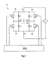
- FIG. 1 shows a circuit arrangement with which a DC motor M can be operated in both directions of rotation can.
- the DC motor M has two connections A1 and A2.
- the transistors T1 to T4 are four diodes D1 to D4 in parallel arranged, the diodes D1 to D4 to the transistors T1 until T4 are polarized in opposite directions.
- the transistor T1 as well 1, the diode D1 is located in an upper left Bridge branch B1, transistor T2 and diode D2 in one upper right bridge branch B2, the transistor T3 and the diode D3 in a lower left bridge arm B3 and the transistor T4 and the diode D4 in a lower right bridge arm B4.
- the transistors T1, T2, T3, T4 behave like switches, who are leaders when there is high potential and who are not are conductive when a deep potential through a Control device (ECU) to the base of the respective transistor T1, T2, T3, T4 is created.
- ECU Control device
- Pulse-width-modulated control of the transistors Stranges the bridge circuit shown in Fig. 2 States Z1 to Z4, which are a supply phase VP and Short circuit phase KP of the DC motor M can be assigned.
- the supply and Short-circuit phases VP and KP as well as the states Z1 to Z4.
- the supply phase VP includes the states Z1 and Z4, in which the transistors T2 are conductive and the transistor T4 is not is switched on.
- the short circuit phase KP includes the States Z2 and Z3 in which the transistor T2 is not conductive and the transistor T4 is turned on. each Switching period T thus contains one supply phase VP and one Short circuit phase KP.
- the state Z1 occurs when the transistor T2 is conductive and the transistor T4 are not turned on. It flows a current from connection U1 via the upper right bridge branch B2 in direction R1 through the DC motor M and over the lower left bridge branch B3 for connection U2. This stream generates a positive air gap torque and drives it DC motor on. In state Z1, the current increases rapidly (Fig. 2) and accelerates the DC motor M.
- the electromotive force causes a reversal of the Current direction. As soon as the current falls below the zero line and flows in the opposite direction, state Z3 begins. The Current now flows through the lower right bridge branch B4 the conducting transistor T4 via the lower left Bridge branch B3 through diode D3 to connection A1.
- the DC motor M acts as a generator. Like the electricity and 2 shows voltage waveforms is the current negative and the voltage jumps again. In this State, the current generates a braking torque in the DC motor M.
- the transistor T2 is conductive and the transistor T4 is switched non-conductive. It state Z4 sets in.
- the DC motor M continues to operate as a generator. Because the short circuit of the state Z3 through the non-conductive transistor T4 is interrupted, the flows Current now in negative direction starting from connection U2 over the lower left bridge branch B3 through the diode D3 over the DC motor M and over the upper right bridge branch B2 through diode D2 to connection U1 of voltage source U. It generates a negative torque and feeds power back to the voltage source U. This becomes possible because the induced voltage positive and the total armature voltage larger than the voltage of the voltage source. Switching the Transistor T2 can be done a little later than the switchover of the transistor T4, since the short-circuit current through the diode D2 flows.
- the current in state Z4 decreases in magnitude until one The direction of the current is reversed in the direction of R1.
- the Voltage waveform from FIG. 2 shows that too Beginning of state Z4 the voltage level to a maximum increases, so that the feedback by the DC motor M is made clear. From the time the direction of the Current in direction R1 occurs again state Z1, in which the DC motor M is actively accelerated again.
- the transistor T2 In analogy to the switching states of the Transistors T1 and T3 and for driving the transistors T2 and T4 are used for an opposite direction of rotation of the DC motor M the transistor T2 permanently on and conductive the transistor T4 is switched permanently to non-conductive.
- the Transistors T1 and T3 are controlled with pulse width modulation.
- the Control signals for the transistors T2 and T4 or T1 and T3 can the duration of the individual states Z1 to Z4 and thus the Length of the supply and short-circuit phase VP or KP varies or be set. It has been shown that by choice a relatively high pulse width ratio P the DC motor M can be operated such that during the supply and short-circuit phase VP or KP only the States Z1 and Z2 occur. In this case the DC motor M mostly accelerated and only slightly slowed down, resulting in a high rated speed and a high Torque can be achieved. With a relatively small one The pulse width ratio P can also be the states Z3 and Z4 occur, resulting in a greater deceleration of the DC motor M and thus to a decrease in the nominal speed and the torque leads.
- the circuit arrangement according to the invention is suitable preferably for switching operations in adjustment devices short switching times since it is long-lasting Operating interval of the DC motor, especially in the Short circuit phase, overheating can occur.
- at automated manual transmissions are only short shift times and therefore only short operating intervals to be expected, with which one Overheating of the DC motor is unlikely.
- Fig. 3 is an adjusting device 12 for the Switching device 14 of a synchronizing device 16 automated manual transmission not shown shown schematically.
- the adjusting device 12 contains a direct current motor M. with a reduction gear 18 and an output shaft 20.
- the DC motor M has two connections A1, A2, the the circuit arrangement 10 according to the invention (FIG. 1) are electrically connected.
- the output shaft 20 is non-rotatable connected to one end 22 of a lever 24.
- a Adjustment pin 28 at the second end 26 of the lever 24 is the Lever 24 with an adjustment groove 30 of the switching device 14 in Intervention.
- the switching device 14 contains a switching rod 32, which with a shift fork 34 is firmly connected. On the shift rod 32, the adjustment groove 30 is introduced, in which the Adjustment pin 28 engages. The shift fork 34 engages in one Shift sleeve 36 of the synchronizer 16 of the Manual transmission.
- a synchronization device 16 mentioned above is preferably based on the " Borg-Warner” system and is widely used in vehicle transmissions.
- G. Lechner and H. Naunheimer for example, in “Vehicle Transmission”, Springer-Verlag Berlin Heidelberg New York, 1994, pages 238-241, provide a detailed description of the structure and mode of operation of such a synchronization device 16 or a synchronization.
- the DC motor M is activated.
- the Reduction gear 18 provides a torque that over the Output shaft 20 engages the lever 24. Due to the Rotary movement of the output shaft 20 leads the second end 26 of the Lever 24 pivots. The swivel movement will via the adjusting pin 28 and the adjusting groove 30 on the Transfer shift rod 32 such that the shift rod 32 performs a translatory adjustment movement and accordingly the directions of the double arrow 38 is moved.
- Direction of rotation of the DC motor M moves Shift rod 32 in one direction or the other Double arrow 38.
- Adjustment movement with regard to adjustment force and adjustment speed to vary because of a synchronization process contains several synchronization sections, one different optimization of the adjustment movement with regard on adjustment force and adjustment speed.
- the Control of the DC motor M with the invention Circuit arrangement 10 with variation of the pulse width ratio P enables such an optimization of the Adjustment.
- a high constant pulse width ratio P1 is selected at the beginning during a switching process, as a result of which high acceleration forces are achieved and the static friction forces of the switching sleeve 36 can be overcome.
- Specified synchronization forces must be observed during a synchronization process in order to avoid damage to the components in the synchronization device. Therefore, after a predefinable acceleration time t A, the pulse width ratio P1 is reduced to a smaller constant pulse width ratio P2. This also prevents the adjustment speed from being too high when an end position of the shift sleeve 36 is reached, which can lead to mechanical damage in the synchronizing device 16.
- the switching device 14 and the Synchronizing device 16 can be optimized.
Landscapes
- Engineering & Computer Science (AREA)
- General Engineering & Computer Science (AREA)
- Mechanical Engineering (AREA)
- Power Engineering (AREA)
- Control Of Direct Current Motors (AREA)
- Stopping Of Electric Motors (AREA)
Applications Claiming Priority (2)
| Application Number | Priority Date | Filing Date | Title |
|---|---|---|---|
| DE10226152A DE10226152A1 (de) | 2002-06-13 | 2002-06-13 | Schaltungsanordnung zum Betreiben eines Gleichstrommotors und Verstelleinrichtung mit einer solchen |
| DE10226152 | 2002-06-13 |
Publications (2)
| Publication Number | Publication Date |
|---|---|
| EP1372258A2 true EP1372258A2 (fr) | 2003-12-17 |
| EP1372258A3 EP1372258A3 (fr) | 2004-03-03 |
Family
ID=29557789
Family Applications (1)
| Application Number | Title | Priority Date | Filing Date |
|---|---|---|---|
| EP03011487A Withdrawn EP1372258A3 (fr) | 2002-06-13 | 2003-05-21 | Circuit d'opération d'un moteur à courant continu et un dispositif de réglage utilisant ce circuit |
Country Status (3)
| Country | Link |
|---|---|
| US (1) | US6933691B2 (fr) |
| EP (1) | EP1372258A3 (fr) |
| DE (1) | DE10226152A1 (fr) |
Families Citing this family (6)
| Publication number | Priority date | Publication date | Assignee | Title |
|---|---|---|---|---|
| US7421301B2 (en) * | 2004-09-03 | 2008-09-02 | General Motors Corporation | Speed-variable maximum delay clamping when using variable-delay random PWM switching |
| DE102004057066A1 (de) * | 2004-11-25 | 2006-06-01 | Daimlerchrysler Ag | Elektromechanischer Antrieb |
| GB2552663B (en) * | 2016-08-01 | 2019-07-24 | Protean Electric Ltd | A method and controller for controlling an electric motor |
| DE102019211378A1 (de) * | 2019-07-30 | 2021-02-04 | Vitesco Technologies Germany Gmbh | Anordnung zum Schalten eines Getriebes und Verfahren zum Betrieb der Anordnung |
| WO2021100124A1 (fr) * | 2019-11-19 | 2021-05-27 | 株式会社ミクニ | Dispositif de verrouillage de stationnement électrique |
| EP4400746A1 (fr) | 2023-01-11 | 2024-07-17 | ZF CV Systems Global GmbH | Procédé de changement de vitesse d'une transmission à commande électrique pour un véhicule, en particulier un véhicule utilitaire |
Citations (3)
| Publication number | Priority date | Publication date | Assignee | Title |
|---|---|---|---|---|
| JPH03182874A (ja) * | 1989-12-11 | 1991-08-08 | Omron Corp | 電動式パワー・ステアリング装置におけるモータ駆動装置 |
| DE4209474A1 (de) * | 1992-03-24 | 1993-09-30 | Bosch Gmbh Robert | Einrichtung zur Steuerung wenigstens eines elektrischen Verbrauchers in einem Fahrzeug |
| EP1207618A1 (fr) * | 2000-11-20 | 2002-05-22 | STMicroelectronics S.r.l. | Circuit de récupération de données de vitesse d'un moteur à courant continu et méthode utilisant un tel circuit |
Family Cites Families (21)
| Publication number | Priority date | Publication date | Assignee | Title |
|---|---|---|---|---|
| DE126988C (fr) | ||||
| DE1513181A1 (de) * | 1965-05-13 | 1969-10-23 | Honeywell Gmbh | Betriebsschaltung fuer einen Gleichstrommotor mit umsteuerbarer Drehrichtung |
| US3525883A (en) * | 1967-07-28 | 1970-08-25 | Dover Corp | Bridge amplifier circuit |
| US3743911A (en) * | 1971-06-18 | 1973-07-03 | Gen Electric | Servomotor pulse width control circuit capable of compensating for variations in supply voltage |
| JPS5620395U (fr) * | 1979-07-23 | 1981-02-23 | ||
| US4368411A (en) * | 1981-07-13 | 1983-01-11 | Kollmorgen Technologies Corporation | Control system for electric motor |
| JPS5986498A (ja) * | 1982-11-09 | 1984-05-18 | Seiko Instr & Electronics Ltd | パルス幅変調直流サ−ボモ−タ駆動回路 |
| DE3315664A1 (de) * | 1983-04-29 | 1984-11-08 | Siemens AG, 1000 Berlin und 8000 München | Steuerschaltung zur drehzahlregelung eines gleichstrommotors |
| US4544869A (en) * | 1983-10-05 | 1985-10-01 | Unisen, Inc. | Electronic control circuit for bi-directional motion |
| US4545004A (en) * | 1984-03-22 | 1985-10-01 | General Motors Corporation | Bridge driver circuit for a DC electric motor |
| EP0208508B1 (fr) * | 1985-07-02 | 1993-10-27 | Pioneer Electronic Corporation | Circuit d'attaque à modulation d'impulsions en largeur ou en durée |
| DE3718309A1 (de) | 1987-05-21 | 1988-12-15 | Vdo Schindling | Schaltungsanordnung zur getakteten ansteuerung von halbleiterschaltern |
| JPH062316U (ja) * | 1992-06-12 | 1994-01-14 | 株式会社ニコン | カメラ及びそのアクセサリーに使用されるモータ駆動装置 |
| US5481170A (en) * | 1993-08-11 | 1996-01-02 | Eaton Corporation | Method and apparatus for controlling shift force in an automated mechanical transmission |
| FR2714547B1 (fr) * | 1993-12-23 | 1996-01-12 | Commissariat Energie Atomique | Système de commande d'actionneurs à courant continu en électronique de puissance. |
| US5818178A (en) * | 1995-03-06 | 1998-10-06 | Hitachi, Ltd. | Valve control apparatus for an automobile |
| US5894208A (en) * | 1995-07-28 | 1999-04-13 | Eaton Corporation | Control for electrically actuated shifting mechanism |
| US5801504A (en) * | 1995-09-25 | 1998-09-01 | Nsk Ltd. | Control apparatus for electric power steering system |
| US6341680B1 (en) * | 1997-09-13 | 2002-01-29 | Honda Giken Kogyo Kabushiki Kaisha | Electric-power-assist transmission and its control method |
| DE19848594C2 (de) * | 1997-10-21 | 2002-11-14 | Hitachi Ltd | Elektrisch gesteuerte Drosselklappenvorrichtung |
| US6683437B2 (en) * | 2001-10-31 | 2004-01-27 | Immersion Corporation | Current controlled motor amplifier system |
-
2002
- 2002-06-13 DE DE10226152A patent/DE10226152A1/de not_active Withdrawn
-
2003
- 2003-05-16 US US10/439,510 patent/US6933691B2/en not_active Expired - Lifetime
- 2003-05-21 EP EP03011487A patent/EP1372258A3/fr not_active Withdrawn
Patent Citations (3)
| Publication number | Priority date | Publication date | Assignee | Title |
|---|---|---|---|---|
| JPH03182874A (ja) * | 1989-12-11 | 1991-08-08 | Omron Corp | 電動式パワー・ステアリング装置におけるモータ駆動装置 |
| DE4209474A1 (de) * | 1992-03-24 | 1993-09-30 | Bosch Gmbh Robert | Einrichtung zur Steuerung wenigstens eines elektrischen Verbrauchers in einem Fahrzeug |
| EP1207618A1 (fr) * | 2000-11-20 | 2002-05-22 | STMicroelectronics S.r.l. | Circuit de récupération de données de vitesse d'un moteur à courant continu et méthode utilisant un tel circuit |
Also Published As
| Publication number | Publication date |
|---|---|
| US20040021438A1 (en) | 2004-02-05 |
| US6933691B2 (en) | 2005-08-23 |
| DE10226152A1 (de) | 2003-12-24 |
| EP1372258A3 (fr) | 2004-03-03 |
Similar Documents
| Publication | Publication Date | Title |
|---|---|---|
| DE3783638T2 (de) | Motorantriebsschaltung fuer zwei drehrichtungen. | |
| DE69403937T2 (de) | Steuerung einer induktiven Last | |
| EP0739084A2 (fr) | Procédé de commande ou réglage d'un moteur électrique et dispositif pour mettre en oeuvre ce procédé | |
| DE112017002009B4 (de) | Schaltbereichssteuerungsvorrichtung | |
| EP1683260B1 (fr) | Commande d'un moteur electrique par reglage continu de l'angle de commutation | |
| DE3819062C2 (fr) | ||
| DE2514987C2 (fr) | ||
| DE2546877C2 (de) | Steueranordnung zum Gegenstrombremsen eines thyristor-gesteuerten Gleichstrom-Traktionsmotors | |
| EP2503682B1 (fr) | Agencement de circuit | |
| DE3819064C2 (fr) | ||
| EP0714162B1 (fr) | Circuit de commande d'une moteur commuté électroniquement | |
| EP1372258A2 (fr) | Circuit d'opération d'un moteur à courant continu et un dispositif de réglage utilisant ce circuit | |
| DE2652540A1 (de) | Impulssteuereinrichtung | |
| DE2817360C2 (de) | Regelanordnung für Elektrofahrzeuge | |
| DE3128787A1 (de) | "elektrisch betaetigbare schaltvorrichtung zur umschaltung einer mit verschiedenen drehzahlen antreibbaren triebwelle" | |
| EP0863604B1 (fr) | Méthode et dispositif de contrôle et de régulation d'un ralentisseur employé comme frein auxiliaire de véhicules | |
| DE2930559A1 (de) | Verfahren und schaltungsanordnung zur steuerung der drehzahl eines gleichstrommotors | |
| DE2412895B2 (de) | Drehzahlregelschaltung für eine Nähmaschinenantriebsvorrichtung mit einem Kupplungsmotor | |
| DE1908606A1 (de) | Stellantrieb | |
| DE69800956T2 (de) | Zeitpunktregler | |
| DE4239668C1 (de) | Verfahren zum Ansteuern eines Reluktanzmotors | |
| DE2934316A1 (de) | Verfahren zum betrieb eines gleichstrommotors | |
| DE1940560A1 (de) | Motordrehzahlregler | |
| DE102009018390B4 (de) | Kupplungssteuervorrichtung | |
| EP1783309A2 (fr) | Méthode pour atténues l'impact de butée d'un servomécanisme et servomécanisme pour un moteur à combustion interne |
Legal Events
| Date | Code | Title | Description |
|---|---|---|---|
| PUAI | Public reference made under article 153(3) epc to a published international application that has entered the european phase |
Free format text: ORIGINAL CODE: 0009012 |
|
| AK | Designated contracting states |
Kind code of ref document: A2 Designated state(s): AT BE BG CH CY CZ DE DK EE ES FI FR GB GR HU IE IT LI LU MC NL PT RO SE SI SK TR |
|
| AX | Request for extension of the european patent |
Extension state: AL LT LV MK |
|
| PUAL | Search report despatched |
Free format text: ORIGINAL CODE: 0009013 |
|
| AK | Designated contracting states |
Kind code of ref document: A3 Designated state(s): AT BE BG CH CY CZ DE DK EE ES FI FR GB GR HU IE IT LI LU MC NL PT RO SE SI SK TR |
|
| AX | Request for extension of the european patent |
Extension state: AL LT LV MK |
|
| RIC1 | Information provided on ipc code assigned before grant |
Ipc: 7F 16H 61/32 B Ipc: 7H 02P 7/29 B Ipc: 7H 02P 6/08 B Ipc: 7H 02P 7/00 A |
|
| 17P | Request for examination filed |
Effective date: 20040903 |
|
| AKX | Designation fees paid |
Designated state(s): DE FR GB IT |
|
| 17Q | First examination report despatched |
Effective date: 20111010 |
|
| STAA | Information on the status of an ep patent application or granted ep patent |
Free format text: STATUS: THE APPLICATION IS DEEMED TO BE WITHDRAWN |
|
| 18D | Application deemed to be withdrawn |
Effective date: 20140401 |