EP0734037A2 - Oberflächenmontiertes elektromagnetisches Relais ohne Drahtanschlüsse - Google Patents
Oberflächenmontiertes elektromagnetisches Relais ohne Drahtanschlüsse Download PDFInfo
- Publication number
- EP0734037A2 EP0734037A2 EP96104350A EP96104350A EP0734037A2 EP 0734037 A2 EP0734037 A2 EP 0734037A2 EP 96104350 A EP96104350 A EP 96104350A EP 96104350 A EP96104350 A EP 96104350A EP 0734037 A2 EP0734037 A2 EP 0734037A2
- Authority
- EP
- European Patent Office
- Prior art keywords
- terminals
- base
- relay
- assembly
- movable contact
- Prior art date
- Legal status (The legal status is an assumption and is not a legal conclusion. Google has not performed a legal analysis and makes no representation as to the accuracy of the status listed.)
- Granted
Links
- 239000011810 insulating material Substances 0.000 claims abstract description 15
- XEEYBQQBJWHFJM-UHFFFAOYSA-N Iron Chemical group [Fe] XEEYBQQBJWHFJM-UHFFFAOYSA-N 0.000 claims description 17
- 239000002184 metal Substances 0.000 claims description 5
- 229910052751 metal Inorganic materials 0.000 claims description 5
- 238000007747 plating Methods 0.000 claims description 5
- 238000000465 moulding Methods 0.000 claims description 2
- 239000000565 sealant Substances 0.000 claims description 2
- 238000005452 bending Methods 0.000 claims 1
- 210000002105 tongue Anatomy 0.000 description 15
- 238000005516 engineering process Methods 0.000 description 6
- 230000004048 modification Effects 0.000 description 6
- 238000012986 modification Methods 0.000 description 6
- 239000003990 capacitor Substances 0.000 description 5
- 238000000034 method Methods 0.000 description 5
- 230000007935 neutral effect Effects 0.000 description 3
- 239000000470 constituent Substances 0.000 description 2
- 230000000694 effects Effects 0.000 description 2
- 239000010409 thin film Substances 0.000 description 2
- 230000008878 coupling Effects 0.000 description 1
- 238000010168 coupling process Methods 0.000 description 1
- 238000005859 coupling reaction Methods 0.000 description 1
- 230000002708 enhancing effect Effects 0.000 description 1
- 239000010408 film Substances 0.000 description 1
- 230000013011 mating Effects 0.000 description 1
- 229910000679 solder Inorganic materials 0.000 description 1
Images





Classifications
-
- H—ELECTRICITY
- H01—ELECTRIC ELEMENTS
- H01H—ELECTRIC SWITCHES; RELAYS; SELECTORS; EMERGENCY PROTECTIVE DEVICES
- H01H50/00—Details of electromagnetic relays
- H01H50/14—Terminal arrangements
-
- H—ELECTRICITY
- H01—ELECTRIC ELEMENTS
- H01H—ELECTRIC SWITCHES; RELAYS; SELECTORS; EMERGENCY PROTECTIVE DEVICES
- H01H50/00—Details of electromagnetic relays
- H01H50/02—Bases; Casings; Covers
- H01H50/04—Mounting complete relay or separate parts of relay on a base or inside a case
- H01H50/041—Details concerning assembly of relays
- H01H50/043—Details particular to miniaturised relays
-
- H—ELECTRICITY
- H01—ELECTRIC ELEMENTS
- H01H—ELECTRIC SWITCHES; RELAYS; SELECTORS; EMERGENCY PROTECTIVE DEVICES
- H01H1/00—Contacts
- H01H1/58—Electric connections to or between contacts; Terminals
- H01H2001/5888—Terminals of surface mounted devices [SMD]
-
- H—ELECTRICITY
- H01—ELECTRIC ELEMENTS
- H01H—ELECTRIC SWITCHES; RELAYS; SELECTORS; EMERGENCY PROTECTIVE DEVICES
- H01H50/00—Details of electromagnetic relays
- H01H50/02—Bases; Casings; Covers
- H01H50/04—Mounting complete relay or separate parts of relay on a base or inside a case
- H01H50/041—Details concerning assembly of relays
- H01H50/043—Details particular to miniaturised relays
- H01H2050/044—Special measures to minimise the height of the relay
-
- H—ELECTRICITY
- H01—ELECTRIC ELEMENTS
- H01H—ELECTRIC SWITCHES; RELAYS; SELECTORS; EMERGENCY PROTECTIVE DEVICES
- H01H50/00—Details of electromagnetic relays
- H01H50/02—Bases; Casings; Covers
- H01H50/023—Details concerning sealing, e.g. sealing casing with resin
Definitions
- the present invention relates to a surface mount type electronic device and, more particularly, to a surface mount type leadless electromagnetic relay.
- a surface mounting technology is extensively used for the assembly of various kinds of electronic devices.
- a leadless electromagnetic relay implemented by the surface mounting technology is conventional.
- the leadless electromagnetic relay is provided with so-called gull-wing terminals.
- the problem with the gull-wing terminals is that they protrude downward from the bottom of the relay body and bend to the outside of the relay body.
- the actual mounting height and mounting width of the entire relay are respectively greater than the height and width of the relay body.
- a surface mount type leadless electromagnetic relay has a coil assembly having an iron core, a coil spool containing the iron core such that the iron core is partly exposed to the outside, and coils wound round the coil spool.
- An armature assembly has an armature contacting at least one end portion of the iron core at one end portion thereof, movable contact springs each having at least one movable contact at an end thereof, and a support formed of an insulating material and supporting the armature and movable contact springs.
- a terminal assembly has terminals including stationary contact terminals each holding at least one stationary contact facing the movable contact.
- a base is formed of an insulating material and accommodates the coil assembly therein. The movable contacts, movable contact springs, stationary contacts and terminals of the terminal assembly, which are electrically connected to external circuit from the coils are formed integrally with the base and held in close contact with the bottom of the body of the relay.
- a surface mount type leadless electromagnetic relay has a coil assembly having an iron core, a coil spool containing the iron core such that the iron core is partly exposed to the outside, and coils wound round the coil spool.
- An armature assembly has an armature contacting at least one end portion of the iron core at one end portion thereof, movable contact springs each having at least one movable contact at an end thereof, and a support formed of an insulating material and supporting the armature and movable contact springs.
- a terminal assembly has terminals including stationary contact terminals each holding at least one stationary contact facing the movable contact.
- An upper base is formed of an insulating material, and accommodates the coil assembly.
- a lower base is formed of an insulating material and has on a surface thereof surface terminals formed in a preselected pattern by plating, metal film application or the like and corresponding to the movable contacts, movable contact springs, stationary contacts, and terminals of the terminal assembly electrically connected to external circuit from the coils.
- the upper base and lower base are mechanically and electrically connected to each other, and the surface terminals are extended to the bottom of a body of the relay.
- the relay generally 10
- the relay has a body 12 and gull-wind terminals 14.
- Each gull-wing terminal 14 is implemented by a terminal piece bent in the form of a letter L and extends out from the body 10.
- the mounting area of the relay 10 is greater than the bottom area of the body 12.
- the relay 10 has a mounting width W greater than the width W 0 of the body 12.
- the relay 10 has a height greater than the height of the body 12.
- the relay 10 has a height H greater than the height H 0 of the body 12.
- the relay generally 20, has a casing 100, a coil assembly 200, a terminal assembly 300, and an armature assembly 400.
- the coil assembly 200 includes a coil spool 203 in which a generally U-shaped iron core 201 and coil terminals 202 are embedded.
- the coil spool 203 is formed of an insulating material.
- Coils 204 are wound round the coil spool 203.
- a permanent magnet 206 is fixedly received in a bore 205 formed in the intermediate portion of the core 201.
- the armature assembly 400 has movable contact springs 401 each having a movable contact 401a at its free end and a binge spring 401b at its center, an armature 402, and a support 403 molded integrally with and supporting the contact springs 401 and armature 402.
- the terminal assembly 300 has a base 301 formed of an insulating material, stationary contact terminals 302 each having a stationary contact 302 fixed thereto, neutral terminals 303, and coil lead-out terminals 304.
- the base 301 is provided with a bottom-open box-like configuration and formed with two holes 305 and one hole 306 in the top thereof.
- the holes 305 accommodate the opposite ends of the U-shaped core 201 while the hole 306 accommodates the permanent magnet 206.
- the relay 20 is assembled by the following procedure. First, the coil assembly 200 is inserted into the bottom of the base 301 of the terminal assembly 300, and the coil terminals 202 and coil lead-out terminals 304 are welded or otherwise connected together. Subsequently, the lower portion of the coil assembly 200 is covered with a top-open base 101 constituting the casing 100 and formed of an insulating material. In this sense, the bases 301 and 101 constitute an upper base and a lower base, respectively. The upper base 301 and lower base 101 are coupled or otherwise affixed to each other. After the armature assembly 400 has been mounted to the top of the upper base 301, the hinge springs 401b and neutral terminals 303 are affixed to each other.
- a lug protrudes from the intermediate portion of the bottom of the armature 402 and contacts the top of the magnet 206, so that the armature assembly 400 is fulcrumed by the lug during its tilting movement.
- the terminals are bent in the gull-wing configuration, as shown in FIGS. 1A and 1B.
- FIG. 3 shows the basic structure of another conventional relay of the type described and taught in Japanese Patent Laid-Open Publication No. 4-149924 corresponging to U. S. Patent No. 5,153,543.
- the relay generally 30, is similar to the relay 20 except that the coil terminals 202 are affixed to the coil lead-out terminals 304 beforehand, and then the coil assembly 200 is molded integrally with the base 301.
- the permanent magnet 306 is received in the hole 306 of the base 301.
- the armature assembly 400 is mounted on the top of the magnet 206. This is followed by the same procedure as described in relation to the relay 20. After a cover, not shown, has been fitted on the above assembly, the terminals 302, 303 and 304 are bent, as shown in FIGS. 1A and 1B.
- Japanese Utility Model Laid-Open Publication No. 1-107838 discloses a relay of the type described and made up of a complete relay body having straight terminals, and a socket having gull-wing terminals and produced independently of the relay body.
- the relay body is mounted on the socket. This kind of scheme, however, brings about a problem that the height of the socket increases the overall height of the relay. The mounting area cannot be reduced because the socket has the gull-wing terminals.
- a method of producing a solid-state electrolytic capacitor, which is another leadless device, is taught in Japanese Patent Laid-Open Publication No. 3-30411.
- terminals are bent on the bottom of a capacitor body, so that the original mounting height and mounting area of the capacitor body are achievable.
- the terminals are bent after the molding of the capacitor body, it is likely that they move away from the capacitor body and are distorted.
- Japanese Patent Laid-Open Publication No. 1-109158 proposes a structure for mounting an electronic apparatus by using the surface mounting technology.
- an auxiliary fixing plate is mounted on the rear of a flexible printed wiring board. Lugs protrude from the bottom of the body of the apparatus and pierce the wiring board into the auxiliary board, thereby enhancing reliable connection.
- this kind of scheme cannot reduce the mounting height and area of the surface mounted apparatus.
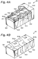
- FIG. 4A shows a relay 40 as seen from above while FIG. 4B shows it as seen from below and in which a cover 500 is absent.
- the relay 40 is similar in basic structure to the relay 30 of FIG. 3 except for the following.
- a base 301 formed of an insulating material is molded integrally with a coil assembly 200.
- terminals 302, 303 and 304 are molded integrally with and in close contact with the base 301, they are prevented from moving away from the base 301 or from being distorted. As shown in FIG. 4B, the portions of the terminals 302, 303 and 304 bent inwardly and positioned on the bottom of the base 301 constitute extensions 302b, 303b and 304b corresponding to solder pads provided on a printed circuit board to which the relay 40 will be mounted.
- the terminals of the relay 40 do not protrude to the outside of the relay body, so that the mounting width of the relay is equal to the width of the relay body.
- the mounting height of the relay is equal to the height of the relay body.
- FIG. 5A shows a second embodiment of the present invention while FIG. 5B shows a portion of the embodiment labeled A in FIG. 5A.
- This embodiment is similar to the first embodiment except for the following.
- a relay 50 has surface terminals 307 in the form of stripes and formed on the top, sides and bottom of the base 301 by plating, metal thin film application or similar technology.
- the stationary contact terminals 302 has a downwardly extending lug 302c.
- the lug 302c is press-fitted in a hole 307a formed in the part of corresponding one of the terminals 302 which is positioned on the top of the base 301.
- Terminals 302 and 307 are mechanically and electrically connected to each other by the press-fitting of the lugs 302c in the corresponding holes 307a.
- the portion of each surface terminal 307 located on the bottom of the base 301 constitutes an extension 307b.
- FIG. 6 shows a modification of the press-fitting scheme shown in FIG. 5B.
- the stationary contact terminal 302d has a bifurcated lug 302d.
- Two holes 307c for press-fitting the bifurcated ends of the lug 302d are formed in the top of the base 301 at the outside of the surface terminal 307.
- FIG. 7A shows a third embodiment of the present invention while FIG. 7B shows it without the cover 500.
- a relay 60 differs from the second embodiment in that the surface terminals 307 in the form of stripes are formed on the sides and bottom of the base 301, and in that tongues 302e extending out from the stationary contact terminals 302 are bent to contact the portions of the surface terminals 307 positioned on the sides of the base 301.
- the portions of the terminals 307 contacting the bottom of the base 301 constitute the extensions 307b.
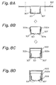
- FIGS. 8A and 8B demonstrate a procedure for encasing the relay body of FIGS. 7A and 7B in the cover 500.
- the stationary contact terminals 302 are each contiguous with one side of the base 301.
- the terminals 302 are cut off at positions indicated by dash-and-dot lines in FIG. 8A, so that they turn out the tongues 302e shown in FIG. 8B.
- the tongues 302e are bent downward such that their free ends contact the surface terminals 307.
- the cover 500 is fitted on the relay body from above, as shown in FIG. 8C.
- the cover 500 reinforces the positive contact of the tongues 302e with the surface terminals 307.
- FIG. 8D shows a modification of the base 301 in the condition shown in FIG. 8C. As shown, the opposite bottom corners of the base 301 are inclined so as to form clearances between them and the cover 500. In this configuration, a sealant 309 can be injected into the clearances. This modification is identical in effect with the above embodiment.
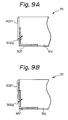
- FIGS. 9A and 9B show a fourth embodiment of the present invention, particularly the base 301 included in a relay 70.
- This embodiment is similar to the third embodiment of FIGS. 7A and 7B except that each tongue 302f has a hook-shaped end 302g.
- the hook-shaped end 302g pierces the associated surface terminal 307 and bites into the base 301, thereby connecting the tongue 302f to the surface terminal 307 electrically and mechanically.
- a clearance may be provided between the end of the tongue 302f opposite to the hook-shaped end 302g and the base 301.
- the gist is that the hook-shaped end 302g pierces the surface terminal 307 and bites into the base 301.
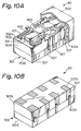
- FIGS. 10A and 10B show a fifth embodiment of the present invention.
- FIG. 10A shows a relay 80 as seen from above while FIG. 10B shows it as seen from below and in which the cover 500 is absent.
- this embodiment differs from the first embodiment of FIGS. 4A and 4B in that the base 301 is made up of an upper base 301A and a lower base 301B, and in that the surface terminals 307 are formed on the surfaces of the lower base 301B by plating, metal thin film application or similar technology.
- the tongues 302e extending from the stationary contact terminals 302 are each bent downward to contact the associated surface terminal 307.
- the portions of the terminals 307 contacting the bottom of the lower base 301B constitute the extensions 307b.
- the electrical and mechanical connection between the tongues 302e and the terminals 307 may be implemented by the configuration shown in FIGS. 7A, 7B and 8A-8D or the configuration shown in FIGS. 9A and 9B, as desired.
- FIGS. 11A-11C show a sixth embodiment of the present invention. This embodiment is similar to the fifth embodiment of FIGS. 10A and 10B except for the following.
- a relay 90 has the surface terminals 307 formed on the top, sides and bottom of the lower base 301B.
- the upper base 301A and lower base 301B respectively have locking portions 301Aa and 301Ba at their edges facing each other.
- the coupling portions 301Aa and 301Ba are engaged with each other so as to cause the lower ends of the tongues 302e extending from the terminals 302 to contact the surface terminals 307.
- the tongues 302e protrude downward from the edges of the upper base 301A and electrically contact the surface terminals 307. It is to be noted that the configuration, position and number of the locking portions 301Aa and 301Ba are open to choice.
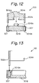
- FIG. 12 shows a seventh embodiment of the present invention, particularly the upper base 301A and lower base 301B.
- This embodiment is similar to the sixth embodiment of FIGS. 11A-11C except for the following.
- a relay 100 has the lower base 301B formed with through bores 301Bb.
- the surface terminals 307 are each provided on the wall of the respective bore 301Bb.
- the tongues 302e extending downward from the edges of the upper base 301A are passed throughout the bores 301Bb and mechanically supported thereby. At the same time, the tongues 302e are electrically connected to the surface terminals 307.
- the upper base 301A and lower base 301B respectively have the locking portions 301Aa and 301Ba at their edges facing each other.
- the tongues 302e and bores 301Bb may each be provided with any desired shape and dimensions.
- the bores 301Bb may be implemented as grooves, if desired.
- the shape, position and number of the locking portions 301Aa and 301Ba are open to choice.
- FIG. 13 shows an eighth embodiment of the present invention, particularly the upper base 301A and lower base 301B.
- This embodiment is similar to the seventh embodiment of FIG. 12 except for the following.
- a relay 110 has the surface terminals 307 each extending from the wall of the associated through bore 301Bb over to the bottom of the lower base 301B by way of the side of the base 301B.
- This embodiment is identical in effect with the seventh embodiment.
- the bores 301Bb may not be through or may even be replaced with grooves, if desired.
- the base may be provided with a top-open box-like configuration for receiving the coil assembly therein.
- the present invention provides a surface mount type leadless electromagnetic relay which eliminates the need for conventional gull-wing terminals.
- the entire relay has a height and a mounting area which are respectively equal to the height and mounting area of its body.
Landscapes
- Physics & Mathematics (AREA)
- Electromagnetism (AREA)
- Switch Cases, Indication, And Locking (AREA)
- Electromagnets (AREA)
Applications Claiming Priority (3)
| Application Number | Priority Date | Filing Date | Title |
|---|---|---|---|
| JP60890/95 | 1995-03-20 | ||
| JP7060890A JPH08255544A (ja) | 1995-03-20 | 1995-03-20 | リードレス表面実装用リレー |
| JP6089095 | 1995-03-20 |
Publications (3)
| Publication Number | Publication Date |
|---|---|
| EP0734037A2 true EP0734037A2 (de) | 1996-09-25 |
| EP0734037A3 EP0734037A3 (de) | 1998-04-22 |
| EP0734037B1 EP0734037B1 (de) | 2001-06-20 |
Family
ID=13155415
Family Applications (1)
| Application Number | Title | Priority Date | Filing Date |
|---|---|---|---|
| EP96104350A Expired - Lifetime EP0734037B1 (de) | 1995-03-20 | 1996-03-19 | Oberflächenmontiertes elektromagnetisches Relais ohne Drahtanschlüsse |
Country Status (5)
| Country | Link |
|---|---|
| US (1) | US5673011A (de) |
| EP (1) | EP0734037B1 (de) |
| JP (1) | JPH08255544A (de) |
| CA (1) | CA2172089C (de) |
| DE (1) | DE69613420T2 (de) |
Cited By (4)
| Publication number | Priority date | Publication date | Assignee | Title |
|---|---|---|---|---|
| WO2000007204A3 (de) * | 1998-07-30 | 2000-08-31 | Tyco Electronics Logistics Ag | Elektromagnetisches relais |
| WO2000007199A3 (de) * | 1998-07-30 | 2000-08-31 | Siemens Electromech Components | Elektromagnetisches relais und verfahren zu dessen herstellung |
| WO2000065619A1 (de) * | 1999-04-22 | 2000-11-02 | Tyco Electronics Logistics Ag | Elektromagnetisches relais und verfahren zu dessen herstellung |
| EP1081733A3 (de) * | 1999-08-31 | 2002-09-11 | Tyco Electronics Logistics AG | Relais mit Wippanker |
Families Citing this family (12)
| Publication number | Priority date | Publication date | Assignee | Title |
|---|---|---|---|---|
| US5880653A (en) * | 1993-09-17 | 1999-03-09 | Omron Corporation | Electromagnetic relay and its manufacture |
| JP2998680B2 (ja) * | 1997-02-27 | 2000-01-11 | 日本電気株式会社 | 高周波リレー |
| JP3843678B2 (ja) | 1999-12-22 | 2006-11-08 | 松下電工株式会社 | 高周波リレー及び高周波リレーの製造方法 |
| CN101281832B (zh) * | 2007-04-05 | 2010-07-21 | 浙江正泰电器股份有限公司 | 接触器的绝缘保护结构 |
| US8344833B1 (en) * | 2011-11-08 | 2013-01-01 | Remy Technologies, L.L.C. | Electric machine including a switch terminal and method of connecting an end portion of a wire to a terminal of an electric machine |
| JP6031322B2 (ja) * | 2012-10-15 | 2016-11-24 | 矢崎総業株式会社 | リレーモジュール及び電気接続箱 |
| JP6433706B2 (ja) * | 2014-07-28 | 2018-12-05 | 富士通コンポーネント株式会社 | 電磁継電器及びコイル端子 |
| JP6451472B2 (ja) | 2015-04-13 | 2019-01-16 | オムロン株式会社 | 電子機器 |
| JP6631068B2 (ja) * | 2015-07-27 | 2020-01-15 | オムロン株式会社 | 接点機構およびこれを用いた電磁継電器 |
| EP3462472B1 (de) * | 2017-09-29 | 2022-04-20 | Tyco Electronics Componentes Electromecânicos Lda | Dichtungsgehäuse für eine elektrische vorrichtung und gedichtetes relais mit verwendung des dichtungsgehäuses |
| CN113012988B (zh) * | 2021-02-25 | 2025-09-12 | 厦门宏发信号电子有限公司 | 一种高可靠绝缘的超小型电磁继电器 |
| EP4607565A1 (de) * | 2024-02-26 | 2025-08-27 | Paramount Industries | Elektromagnetisches relais |
Family Cites Families (11)
| Publication number | Priority date | Publication date | Assignee | Title |
|---|---|---|---|---|
| JPS5931232B2 (ja) * | 1977-11-17 | 1984-07-31 | 松下電器産業株式会社 | GaN発光素子 |
| DE8424457U1 (de) * | 1984-08-17 | 1986-02-13 | Siemens AG, 1000 Berlin und 8000 München | Sockel für ein elektromagnetisches Relais |
| DE3538636A1 (de) * | 1985-10-30 | 1987-05-07 | Siemens Ag | Elektromagnetisches relais |
| US4812794A (en) * | 1987-02-17 | 1989-03-14 | American Telephone & Telegraph Company, At&T Bell Laboratories | Electrical relay apparatus |
| DE3730179A1 (de) * | 1987-09-09 | 1989-03-23 | Henkel Kgaa | Verdickte waessrige tensidloesungen, insbesondere fuer deren einsatz auf dem gebiet kosmetischer praeparate |
| JP2681945B2 (ja) * | 1987-10-21 | 1997-11-26 | アイシン精機株式会社 | 液圧ブレーキ装置 |
| JPH0330411A (ja) * | 1989-06-28 | 1991-02-08 | Elna Co Ltd | 固体電解コンデンサの製造方法 |
| JPH04149924A (ja) * | 1990-10-15 | 1992-05-22 | Nec Corp | 電磁継電器 |
| CA2085967C (en) * | 1991-12-24 | 1997-11-11 | Kazuhiro Nobutoki | Polarized relay |
| JP3472881B2 (ja) * | 1993-02-24 | 2003-12-02 | オムロン株式会社 | 電磁継電器の製造方法 |
| JP3463310B2 (ja) * | 1993-03-12 | 2003-11-05 | オムロン株式会社 | 表面実装リレー |
-
1995
- 1995-03-20 JP JP7060890A patent/JPH08255544A/ja active Pending
-
1996
- 1996-03-18 US US08/617,425 patent/US5673011A/en not_active Expired - Fee Related
- 1996-03-19 EP EP96104350A patent/EP0734037B1/de not_active Expired - Lifetime
- 1996-03-19 CA CA002172089A patent/CA2172089C/en not_active Expired - Fee Related
- 1996-03-19 DE DE69613420T patent/DE69613420T2/de not_active Expired - Fee Related
Cited By (4)
| Publication number | Priority date | Publication date | Assignee | Title |
|---|---|---|---|---|
| WO2000007204A3 (de) * | 1998-07-30 | 2000-08-31 | Tyco Electronics Logistics Ag | Elektromagnetisches relais |
| WO2000007199A3 (de) * | 1998-07-30 | 2000-08-31 | Siemens Electromech Components | Elektromagnetisches relais und verfahren zu dessen herstellung |
| WO2000065619A1 (de) * | 1999-04-22 | 2000-11-02 | Tyco Electronics Logistics Ag | Elektromagnetisches relais und verfahren zu dessen herstellung |
| EP1081733A3 (de) * | 1999-08-31 | 2002-09-11 | Tyco Electronics Logistics AG | Relais mit Wippanker |
Also Published As
| Publication number | Publication date |
|---|---|
| US5673011A (en) | 1997-09-30 |
| CA2172089A1 (en) | 1996-09-21 |
| EP0734037A3 (de) | 1998-04-22 |
| DE69613420T2 (de) | 2002-05-02 |
| DE69613420D1 (de) | 2001-07-26 |
| CA2172089C (en) | 1999-08-03 |
| EP0734037B1 (de) | 2001-06-20 |
| JPH08255544A (ja) | 1996-10-01 |
Similar Documents
| Publication | Publication Date | Title |
|---|---|---|
| US5673011A (en) | Surface mount type leadless electromagnetic relay | |
| KR100333935B1 (ko) | 전자접촉기 | |
| EP1592037B1 (de) | Elektromagnetisches Relais | |
| EP0481371A2 (de) | Elektromagnetisches Relais | |
| EP1244127B1 (de) | Elektrisches Schaltelement | |
| US5894253A (en) | Electromagnetic relay | |
| US6960972B2 (en) | High-frequency relay having a conductive and grounding base covering at least a bottom surface of a body | |
| US6057749A (en) | Structure and method for connection of an electrical component to an electromagnetic relay | |
| KR19990036798A (ko) | 전자 릴레이와 전기 부품을 접속시키는 장치 및 방법 | |
| EP1592036B1 (de) | Elektromagnetisches Relais | |
| EP0627119B1 (de) | Polarisiertes relais | |
| US6448877B1 (en) | Electromagnetic relay having a reduced height | |
| JPH11144823A (ja) | プリント基板用コネクタ及びその実装構造 | |
| US20250132115A1 (en) | Electromagnetic relay | |
| JP2890554B2 (ja) | 高周波リレー | |
| JP3357922B2 (ja) | 電磁継電器 | |
| JP3219416B2 (ja) | 電磁継電器 | |
| JP3304874B2 (ja) | 接極子ブロック及び電磁継電器 | |
| US5331302A (en) | Miniature transfer relay | |
| JPH0735278Y2 (ja) | 高周波リレー | |
| JP3158646B2 (ja) | プリント配線板 | |
| JPH11176664A (ja) | 巻線部品用端子台、および表面実装型巻線部品 | |
| JP3119597B2 (ja) | 電磁継電器およびその製造方法 | |
| JP2954097B2 (ja) | 高周波リレー | |
| JP4201298B2 (ja) | 電磁型発音体 |
Legal Events
| Date | Code | Title | Description |
|---|---|---|---|
| PUAI | Public reference made under article 153(3) epc to a published international application that has entered the european phase |
Free format text: ORIGINAL CODE: 0009012 |
|
| AK | Designated contracting states |
Kind code of ref document: A2 Designated state(s): DE FR GB |
|
| PUAL | Search report despatched |
Free format text: ORIGINAL CODE: 0009013 |
|
| AK | Designated contracting states |
Kind code of ref document: A3 Designated state(s): DE FR GB |
|
| 17P | Request for examination filed |
Effective date: 19980408 |
|
| 17Q | First examination report despatched |
Effective date: 19991221 |
|
| GRAG | Despatch of communication of intention to grant |
Free format text: ORIGINAL CODE: EPIDOS AGRA |
|
| GRAG | Despatch of communication of intention to grant |
Free format text: ORIGINAL CODE: EPIDOS AGRA |
|
| GRAH | Despatch of communication of intention to grant a patent |
Free format text: ORIGINAL CODE: EPIDOS IGRA |
|
| GRAH | Despatch of communication of intention to grant a patent |
Free format text: ORIGINAL CODE: EPIDOS IGRA |
|
| GRAA | (expected) grant |
Free format text: ORIGINAL CODE: 0009210 |
|
| AK | Designated contracting states |
Kind code of ref document: B1 Designated state(s): DE FR GB |
|
| REF | Corresponds to: |
Ref document number: 69613420 Country of ref document: DE Date of ref document: 20010726 |
|
| ET | Fr: translation filed | ||
| REG | Reference to a national code |
Ref country code: GB Ref legal event code: IF02 |
|
| PLBE | No opposition filed within time limit |
Free format text: ORIGINAL CODE: 0009261 |
|
| STAA | Information on the status of an ep patent application or granted ep patent |
Free format text: STATUS: NO OPPOSITION FILED WITHIN TIME LIMIT |
|
| 26N | No opposition filed | ||
| REG | Reference to a national code |
Ref country code: GB Ref legal event code: 732E |
|
| REG | Reference to a national code |
Ref country code: FR Ref legal event code: TP |
|
| PGFP | Annual fee paid to national office [announced via postgrant information from national office to epo] |
Ref country code: FR Payment date: 20060308 Year of fee payment: 11 |
|
| PGFP | Annual fee paid to national office [announced via postgrant information from national office to epo] |
Ref country code: GB Payment date: 20060315 Year of fee payment: 11 |
|
| PGFP | Annual fee paid to national office [announced via postgrant information from national office to epo] |
Ref country code: DE Payment date: 20060316 Year of fee payment: 11 |
|
| GBPC | Gb: european patent ceased through non-payment of renewal fee |
Effective date: 20070319 |
|
| REG | Reference to a national code |
Ref country code: FR Ref legal event code: ST Effective date: 20071130 |
|
| PG25 | Lapsed in a contracting state [announced via postgrant information from national office to epo] |
Ref country code: DE Free format text: LAPSE BECAUSE OF NON-PAYMENT OF DUE FEES Effective date: 20071002 |
|
| PG25 | Lapsed in a contracting state [announced via postgrant information from national office to epo] |
Ref country code: GB Free format text: LAPSE BECAUSE OF NON-PAYMENT OF DUE FEES Effective date: 20070319 |
|
| PG25 | Lapsed in a contracting state [announced via postgrant information from national office to epo] |
Ref country code: FR Free format text: LAPSE BECAUSE OF NON-PAYMENT OF DUE FEES Effective date: 20070402 |