EP0734749A2 - Procédé pour séparer un produit biologique - Google Patents
Procédé pour séparer un produit biologique Download PDFInfo
- Publication number
- EP0734749A2 EP0734749A2 EP96104919A EP96104919A EP0734749A2 EP 0734749 A2 EP0734749 A2 EP 0734749A2 EP 96104919 A EP96104919 A EP 96104919A EP 96104919 A EP96104919 A EP 96104919A EP 0734749 A2 EP0734749 A2 EP 0734749A2
- Authority
- EP
- European Patent Office
- Prior art keywords
- matrix
- stamp
- elution
- biological material
- vessel
- Prior art date
- Legal status (The legal status is an assumption and is not a legal conclusion. Google has not performed a legal analysis and makes no representation as to the accuracy of the status listed.)
- Granted
Links
Images


Classifications
-
- B—PERFORMING OPERATIONS; TRANSPORTING
- B01—PHYSICAL OR CHEMICAL PROCESSES OR APPARATUS IN GENERAL
- B01D—SEPARATION
- B01D15/00—Separating processes involving the treatment of liquids with solid sorbents; Apparatus therefor
-
- G—PHYSICS
- G01—MEASURING; TESTING
- G01N—INVESTIGATING OR ANALYSING MATERIALS BY DETERMINING THEIR CHEMICAL OR PHYSICAL PROPERTIES
- G01N33/00—Investigating or analysing materials by specific methods not covered by groups G01N1/00 - G01N31/00
- G01N33/48—Biological material, e.g. blood, urine; Haemocytometers
- G01N33/50—Chemical analysis of biological material, e.g. blood, urine; Testing involving biospecific ligand binding methods; Immunological testing
- G01N33/53—Immunoassay; Biospecific binding assay; Materials therefor
- G01N33/543—Immunoassay; Biospecific binding assay; Materials therefor with an insoluble carrier for immobilising immunochemicals
- G01N33/54306—Solid-phase reaction mechanisms
-
- B—PERFORMING OPERATIONS; TRANSPORTING
- B01—PHYSICAL OR CHEMICAL PROCESSES OR APPARATUS IN GENERAL
- B01D—SEPARATION
- B01D15/00—Separating processes involving the treatment of liquids with solid sorbents; Apparatus therefor
- B01D15/08—Selective adsorption, e.g. chromatography
- B01D15/26—Selective adsorption, e.g. chromatography characterised by the separation mechanism
- B01D15/38—Selective adsorption, e.g. chromatography characterised by the separation mechanism involving specific interaction not covered by one or more of groups B01D15/265 and B01D15/30 - B01D15/36, e.g. affinity, ligand exchange or chiral chromatography
- B01D15/3804—Affinity chromatography
-
- Y—GENERAL TAGGING OF NEW TECHNOLOGICAL DEVELOPMENTS; GENERAL TAGGING OF CROSS-SECTIONAL TECHNOLOGIES SPANNING OVER SEVERAL SECTIONS OF THE IPC; TECHNICAL SUBJECTS COVERED BY FORMER USPC CROSS-REFERENCE ART COLLECTIONS [XRACs] AND DIGESTS
- Y10—TECHNICAL SUBJECTS COVERED BY FORMER USPC
- Y10S—TECHNICAL SUBJECTS COVERED BY FORMER USPC CROSS-REFERENCE ART COLLECTIONS [XRACs] AND DIGESTS
- Y10S436/00—Chemistry: analytical and immunological testing
- Y10S436/807—Apparatus included in process claim, e.g. physical support structures
Definitions
- Isolation methods for biological materials exist in different types, depending on the biological material to be isolated and its subsequent use.
- the biological material e.g. B. an antigen, antibody or a nucleic acid
- the binding of the biological material in this case is usually so specific that only the biological material to be detected later is immobilized on the surface. In these methods, the biological material is not released again and is even harmful for a subsequent quantitative determination.
- a second type of process uses swellable, porous materials for the separation of biological materials, e.g. B. according to their molecular weight.
- biological materials e.g. B. according to their molecular weight.
- the biological material is not bound to a solid phase.
- the separation takes place essentially using the different penetration behavior of biological materials due to the different sizes.
- the elution liquid was conveyed through the porous matrix either by applying pressure in the running direction of the liquid or negative pressure on the side of the liquid outlet or by centrifuging the column, whereby the elution liquid was thrown out of the porous matrix.
- this method uses vacuum pumps or centrifugators, i.e. devices that are often used in routine medical diagnostics only for this single type of application.
- their use, in particular of the centrifugators is time-consuming and does not allow continuous processing of analyzes.
- the invention relates to a method for isolating a biological material by providing biological material bound to a compressible porous matrix and compressing the matrix and under conditions in which the biological material is released from the surface of the matrix into an elution liquid.
- the invention also relates to a system for isolating the biological material.
- Isolation processes are understood to mean processes in which one or more constituents of a mixture are separated from the other constituents of this mixture.
- a biological material is understood to mean those organic compounds which are related to living things such as animals, humans, viruses, bacteria or plants. These include, for example, the ingredients of living things. Particularly preferred ingredients are those which are either in dissolved form or which can be brought into solution in a liquid, but which can also be bound to a solid matrix. These include, on the one hand, low-molecular substances (with a molecular weight of less than 2,000 D), such as vitamins, but also therapeutically active substances and hormones, but also high-molecular substances (with a molecular weight of more than 2,000 D), such as biopolymers, which are made up of monomer units . These include, for example, proteins and nucleic acids. The method according to the invention is particularly suitable for isolating nucleic acids. In the case of the proteins, particular preference is given to the immunologically active substances, such as antigens and antibodies.
- the compressible porous matrix according to the invention represents a spatially extended structure which has an insoluble part made of the above-mentioned material and a part which can be filled up with liquid.
- This refillable portion is also referred to below as the internal volume.
- the internal volume expands between the insoluble portion. As a result, it forms a system of interconnected pores or empty spaces. This system could also be described as preferably open-pore.
- the insoluble part also forms a spatially extended structure in this system, which is preferably also connected.
- the matrix is a multi-component system, e.g. B. a system in which a particulate component between two particulate components in the direction of the interior (C14) or in the direction of the lower opening in the molded body holding liquid-permeable components, for. B. fleece is sealed.
- the particulate component can then e.g. B. form a slurry between the two components; to obtain the liquid, the two components are pushed towards one another, which compresses the slurry and reduces the volume of liquid contained therein.
- Examples of such a compressible porous matrix are sponge-like structures and structures made of fibers, e.g. B. fleeces.
- the matrix is preferably absorbent with respect to the liquid and wettable on its surface by the sample liquid.
- a matrix is referred to as compressible in the sense of the invention if the internal volume can be reduced by 50% or more, preferably 70% or more, particularly preferably 90% or more, by compressing the spatially expanded structure consisting of the insoluble portion and the internal volume. A complete disappearance of the inner volume will probably not be possible for practical reasons, which is why a certain proportion of the inner volume and thus of liquid will generally remain in the matrix.
- the volume fraction of the insoluble material to the internal volume is preferably in a range between 10: 1 and 1: 100, particularly preferably between 1: 1 and 1:50.
- the compressibility of the porous matrix does not necessarily have to be reversible, ie if the pressure on the matrix is removed, this matrix does not necessarily have to return to its original shape.
- the extent of the matrix depends, among other things, on the amount of biological material to be bound.
- the outer shape can be any. It aligns itself inter alia, according to the type of immobilization of the biological material and the subsequent release.
- the matrix preferably has the shape of a plate.
- the insoluble material of the matrix can be chosen such that the biological material has an affinity for the material so that binding takes place.
- a glass fiber fleece is used as the insoluble material. It is known that all nucleic acids have a certain affinity for glass surfaces. If the material itself has no affinity for the biological material to be isolated, this material can be modified on its surface so that binding takes place.
- capture probes e.g. H. Nucleic acids which have a sequence complementary to the nucleic acid to be isolated are bound to the surface.
- immunologically reactive compounds such as. B. antigens or antibodies
- the corresponding immune partner can be immobilized, d. H. Antibodies or antigens.
- the methods that are also known for non-porous materials are available for binding the capture probes or immunoreactive compounds.
- the biological material bound to the compressible, porous, matrix can be provided, for example, by bringing the matrix into contact with a solution of the biological material and incubating it for a sufficient time. Since in the general case the amount of solution in which the biological material is present will be greater than the internal volume of the matrix, it is preferred to pass the solution through the matrix, e.g. B. by suction or centrifugation. However, the solution is particularly preferably pressed through the matrix in a vessel without the need to apply a vacuum and a centrifugation step. The liquid present in the interior of the matrix, which contains non-binding constituents of the solution, is then preferably removed from the matrix, for. B. also by suction, centrifugation or squeezing. If desired, the matrix, which now contains the biological material bound, can be washed and freed of any adhering impurities.
- the essence of the invention lies in the way in which the biological material is released from the matrix. Because the matrix is compressible and porous, under conditions in which the biological material is released from the surface of the matrix into an elution liquid, a solution of the isolated biological material can be obtained by compressing the matrix. Compression is understood to mean compressing the spatially extended structure, with liquid being pressed out of the internal volume of the structure. This increases the proportion of the insoluble Material in the overall structure, while the proportion of the remaining internal volume is reduced.
- the matrix is compressed by preferably more than 40% and particularly preferably more than 60%. The extent of the compression also depends, among other things, on the desired amount of liquid that the biological material is to contain.
- the liquid emerging from the matrix can be obtained and processed in any desired manner.
- an elution liquid is understood to be a liquid in which the biological material to be isolated can be dissolved. It has such a chemical composition that the balance between the insoluble material and the solution is shifted on the solution side. In the case of isolation of nucleic acids, a solution is therefore used as the elution liquid which has a lower salt content than the solution from which the nucleic acids were bound to the insoluble material.
- the method according to the invention preferably takes place in a system.
- the compressible porous matrix with the biological material bound to it is introduced into an elution vessel.
- the compressible porous matrix is preferably part of a vessel whose shape is adapted to the interior of the elution vessel.
- the matrix is mixed with elution liquid and then compressed with the aid of a stamp, with a possibility for the liquid to escape either in the stamp or in the vessel containing the matrix or the elution vessel or between these components.
- the materials used for the construction of the said vessels are preferably those which are to be brought into the desired shape by injection molding, for.
- plastics such as polystyrene, particularly preferably polypropylene, optionally with suitable additives.
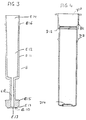
- FIG. 1 shows a shaped body C in the form of a vessel which contains a compressible porous matrix in its lower part (longitudinal section).
- FIG. 2 shows a system according to the invention in a state in which the matrix is compressed (longitudinal section).
- FIG 3 shows a stamp according to the invention for compressing the matrix and for taking up the elution liquid (longitudinal section).
- FIG. 4 shows an elution vessel D which is advantageously suitable for pressing out a compressible porous matrix (longitudinal section).
- FIG. 5 schematically shows the process steps and constructs involved for a process for isolating a biological material according to the invention.
- a shaped body (C) is shown in longitudinal section, which has an essentially hollow cylindrical shape and which has an upper and a lower opening.
- the compressible porous matrix (C11) is fixed in the lower part by constrictions in the cross section of the tube. This matrix is held at the bottom by an edge (C19) and at the top by a circumferential, breakable web (C18). By providing a predetermined breaking point along the inner wall (C16) of the molded body, this web can be broken off and pushed in the direction of the matrix (C11).
- the molded body (C) also contains an outer contour (C12) and an interior, which is designed as a hollow body (C14).
- means for fixing (C17) a stamp (E) in the shaped body are preferably located on this shaped body. This means is preferably designed such that the stamp is fixed in a position in which it compresses the matrix (C11).
- the molded body (C) preferably has means (C15) for fixing a lid on the upper opening.
- Means (C13) for fixing the molded body in the elution vessel (D) can also be provided.
- FIG. 2 shows a particularly preferred system according to the invention. It consists of the elution vessel (D), molded body (C), stamp (E) and lid (B).
- the lid (B) is designed so that it closes the whole of the vessels. 2, the system is shown in a form in which the elution liquid originally in the matrix was pressed out of this matrix into the interior (C12) of the stamp.
- the extrusion pressure on the matrix can be determined in a specific force range via the snap-in length of the punch (E) and the position of the snap-in notch in the molded body (C).
- the lower geometry of the stamp (E) represents an extrusion stamp, the form-fitting Geometry of the pressure surface (E10) is suitable to ensure the pressing of the matrix.
- the shape of the stamp is designed so that the dead volume is minimized.
- the cutouts (E 17) ensure that the broken bar (C18) is picked up.
- the lower area of the stamp has a cylindrical bore traversal through the entire module with a relatively small diameter and a suitable height, which is used both for receiving the squeezed-out solution containing nucleic acid and for removing it by means of a pipette tip.
- the bore (E18) is relatively narrow compared to the possible internal volume of the stamp.
- the bore (E18) ends on the one hand in the opening (E13) in the pressure surface. On the other hand, it leads into the interior of the stamp (E12).
- the upper area of the stamp also represents a traversal bore, which serves as a collecting vessel for the solution of the biological material obtained and, compared to the lower area, has a relatively large diameter and a suitable height.
- the diameter and the height of the bore are selected so that they are suitable for inserting a pipette into the interior (E12) and removing the solution that has entered the interior through the bore (E18).
- a preferred elution vessel (D) is shown in longitudinal section in FIG. 4. It has an inlet opening (D10) through which liquids or other functional elements can be introduced into the elution vessel. In addition, it has an inner edge (D11) which is capable of fastening a cover (B). Also in the upper part of the elution vessel there is a snap-in notch (D12) with which the molded body (C) can be fixed via its means (C13). Another preferred feature is means for fastening the elution vessel (D13) in a perforated plate of suitable diameter. A particularly advantageous feature is the pressure surface (D14) in the lower part of the elution vessel. The dead volume within the vessel can be reduced by adapting this area to the lower part of the molded body. This leads to the particularly effective extraction of the biological material.
- a cell-containing sample liquid is incubated in a sample vessel (A) with a material to which the cells from which nucleic acids are to be obtained are bound.
- this material can either have specific binding properties for the surface of the cells, e.g. B. by immobilizing antibodies against surface antigens or an absorber material (A16), but a material with filter properties (A15) can also be provided, through which the cells are retained when the liquid passes through the material, e.g. B. is removed from the sample vessel.
- the sample vessel is preferably closed by a lid (B) in order to ensure active or passive protection against contamination.
- the liquid is removed from the sample vessel, while cells whose nucleic acids are to be isolated remain in the sample vessel in the state bound to the material.
- the cell-binding material is particulate
- retention can also be achieved by the material being magnetic and by applying a magnetic field to the sample vessel from outside which is so strong that the particulate material remains in the sample vessel when the liquid is removed.
- the liquid can be removed in a variety of ways.
- the liquid can be removed through an outlet opening (A11) spatially separated from the inlet opening (A10). If the outlet opening is located in the lower part of the sample vessel and below the retained cells, the liquid, for. B. under a slight vacuum, are suctioned off.
- a valve can be provided at the outlet opening, which opens by applying negative pressure.
- washing steps can be provided in order to largely remove any interfering sample components from the cells.
- a washing liquid is poured into the sample vessel, in which possible contaminants dissolve, but which do not significantly impair the binding of the cells to the surface of the cell-binding material.
- Such washing solutions are z. B. known from the cell separation protocols or from corresponding cleaning kit protocols for nucleic acids. They essentially depend on the type of binding of the cells to the material.
- the cleaned, enriched cells are brought into contact with a suitable lysis liquid to release the nucleic acids from the cells.
- the reagents of this lysis solution largely depend on the type of immobilized cells. If the cells are bacteria, the lysis solution preferably contains proteinase K to break down the cell wall. If desired, the lysis is supported by heating or cooling and mixing the reaction mixture. If the cell-binding material is magnetic particles, the mixing can also be carried out using magnets. Mixing is also possible by shaking the sample vessel. At the end of this digestion, the nucleic acids to be isolated are freely available in the solution.
- the reaction vessel is preferably closed by a lid in order to prevent contamination from the environment.
- the lid is removed, preferably with the aid of an appropriate mechanical device.
- a shaped body (C) is then introduced into the sample vessel, which contains a mixture of degradation products of the cells and the nucleic acids, the outer contour (C 12) of which is matched to the inner contour (A10) of the sample vessel.
- This molded body is hollow and closed in the direction of the sample vessel and the reaction mixture by a filter (C11).
- the molded body (C) is preferably introduced with the aid of a component (B20) of the cover (B), which also contains a component (B10) which is suitable for closing the sample vessel.
- the molded body is inserted into the sample vessel simultaneously with the closure of the sample vessel (II, III).
- the reaction mixture will also penetrate through the filter (C11) into the cavity (C14) of the shaped body (IV).
- the provision of the filter on the one hand prevents large particles from entering the cavity and, on the other hand, if the filter has nucleic acid-binding properties, binding of the nucleic acids to the filter can already be achieved during the passage of the reaction mixture. In this case, it is advisable to choose a filter material containing glass fibers.
- the remaining lysis reaction mixture is removed from the device formed by A and C, e.g. B. by suction through an underlying outlet opening (A12) in the sample vessel.
- the solution which has penetrated into the hollow body (C14) of the shaped body is thus also removed, so that the filter contains as little liquid residues as possible (V).
- an elution vessel (D) is prepared for receiving the shaped body (C).
- a lid (B) which may be on this vessel is removed VI).
- an elution solution is preferably introduced into the elution vessel, e.g. B. pipetted.
- the composition The elution solution depends on the type of binding of the nucleic acids to the material in the matrix (C11). It contains reagents, under the influence of which the immobilized nucleic acids are eluted, ie dissolved, from the material.
- a new lid (B) is placed on the sample vessel (A) and the molded body (C) (VII).
- the elution liquid introduced penetrates into the matrix (C11) and this detaches the immobilized nucleic acid from the insoluble material.
- the matrix C11
- the elution solution with the redissolved nucleic acids penetrates into the hollow body (C14). So that the elution of the nucleic acids proceeds as completely as possible, the inner contour of the elution vessel should be adapted as closely as possible to the outer contour of the shaped body.
- the lid can be removed (XII) and the desired amount can be removed via an opening in the interior of the stamp, e.g. B. in a pipetting process (XIV). The lid can then be replaced.
- Steps b and c can be exchanged in this order.
- the elution liquid with the biological material which has penetrated into the interior (C12) can then be stored in the system (preferably with the lid closed) or removed with the aid of a pipette and processed further in any way.
- the method according to the invention is particularly suitable for producing relatively highly concentrated solutions of biological materials. According to the invention, a particularly low aerosol formation of nucleic acids from the matrix is achieved. In addition, the type of processing steps greatly simplifies the automation of work processes and processes for isolating biological materials.
- the stamp can be described by the following dimensions: Length: 38.6 mm Outer diameter: 5.8 mm Inside diameter: 5.0 mm.
- the lower part has a punch geometry with a central bore (E13), the upper part represents a collecting vessel (E12) that is open at the top.
- the outer lateral surface (E) has snap-in lips (E16) in the upper area, which are suitable for anchoring and fixing in the molded body (C).
- the circumferential snap lip is 3.5 mm below the top edge, it has a depth of 0.3 mm and a height of 0.25 mm.
- the stamp In the lower area the stamp has sealing lips (E15), which seal the stamp against the molded body. They are raised 0.28 mm and 0.10 mm wide.
- the upper opening of the stamp has an internal geometry for coupling a multifunctional lid (B) and the elution vessel (D).
- the stamp (E) is designed so that it can be inserted into the molded body (C) and closes the entire system together with the cover (B).
- Sample material Length standard II, Boehringer Mannheim Binding buffer: Qiagen AL 1 / AL 2 (4 parts / 1 part), Qiagen Wash buffer: Qiagen AW buffer, from Qiagen Elution buffer: 10 mM Tris buffer pH 9.0
- Sample vessel (A) is filled with 200 ⁇ l sample, 25 ⁇ l proteinase K solution and 200 ⁇ l binding buffer.
- the sample container (A) is closed with the sample container cover (B).
- the liquids are mixed in a closed vessel.
- the incubation is then carried out at 70 ° C. for 10 minutes (disruption of the cells) followed by a cooling phase to 20 ° C. in 3 minutes.
- the sample vessel (A) is opened and 210 ⁇ l ethanol is added.
- the sample vessel (A) is closed and the solution mixed.
- the sample container (A) is opened.
- the sample vessel cover (B) takes the molded body (C) with a porous matrix from the template.
- the molded body with the glass fleece matrix is introduced through the inlet opening into the sample vessel filled with liquid.
- the liquid in the sample vessel (A) flows through the glass fleece from below during the insertion process.
- the freely moving nucleic acid binds to the glass fleece matrix.
- the liquid in the molded body (C) is suctioned off downwards. The liquid flows through the glass fleece again and nucleic acid that is not yet bound is fixed to the matrix.
- the glass fleece matrix is cleaned twice with 500 ⁇ l washing buffer.
- the buffer solution standing above the matrix is sucked off through the glass fleece.
- the matrix with the purified nucleic acid is then dried at 50 ° C./3 min.
- the sample vessel lid (B) is discarded.
- the shaped body (C) with the nucleic acid is transferred from the sample vessel (D) into a prepared elution buffer with 200 ⁇ l elution buffer by means of the elution vessel cover (E).
- the elution buffer detaches the nucleic acid from the glass fleece matrix.
- the nucleic acid solution is partially above the matrix.
- Test series 1 Sample concentration: 6 ⁇ g nucleic acid / 200 ⁇ l elution solution
- Test series 2 Sample concentration: 20 ⁇ g nucleic acid / 200 ⁇ l elution solution
Landscapes
- Health & Medical Sciences (AREA)
- Chemical & Material Sciences (AREA)
- Immunology (AREA)
- Life Sciences & Earth Sciences (AREA)
- Engineering & Computer Science (AREA)
- Molecular Biology (AREA)
- Chemical Kinetics & Catalysis (AREA)
- Biomedical Technology (AREA)
- Analytical Chemistry (AREA)
- Hematology (AREA)
- Urology & Nephrology (AREA)
- Medicinal Chemistry (AREA)
- Pathology (AREA)
- Food Science & Technology (AREA)
- Cell Biology (AREA)
- Physics & Mathematics (AREA)
- Biotechnology (AREA)
- Biochemistry (AREA)
- General Health & Medical Sciences (AREA)
- General Physics & Mathematics (AREA)
- Microbiology (AREA)
- Apparatus Associated With Microorganisms And Enzymes (AREA)
- Investigating Or Analysing Biological Materials (AREA)
- Sampling And Sample Adjustment (AREA)
- Preparation Of Compounds By Using Micro-Organisms (AREA)
- Medicines Containing Material From Animals Or Micro-Organisms (AREA)
- Soy Sauces And Products Related Thereto (AREA)
- Organic Low-Molecular-Weight Compounds And Preparation Thereof (AREA)
- Immobilizing And Processing Of Enzymes And Microorganisms (AREA)
Applications Claiming Priority (2)
| Application Number | Priority Date | Filing Date | Title |
|---|---|---|---|
| DE19512361 | 1995-04-01 | ||
| DE19512361A DE19512361A1 (de) | 1995-04-01 | 1995-04-01 | Verfahren zur Isolierung eines biologischen Materials |
Publications (3)
| Publication Number | Publication Date |
|---|---|
| EP0734749A2 true EP0734749A2 (fr) | 1996-10-02 |
| EP0734749A3 EP0734749A3 (fr) | 1996-11-20 |
| EP0734749B1 EP0734749B1 (fr) | 2002-09-25 |
Family
ID=7758609
Family Applications (1)
| Application Number | Title | Priority Date | Filing Date |
|---|---|---|---|
| EP96104919A Expired - Lifetime EP0734749B1 (fr) | 1995-04-01 | 1996-03-28 | Procédé pour séparer un produit biologique |
Country Status (6)
| Country | Link |
|---|---|
| US (1) | US6258531B1 (fr) |
| EP (1) | EP0734749B1 (fr) |
| JP (1) | JP2883845B2 (fr) |
| DE (2) | DE19512361A1 (fr) |
| ES (1) | ES2182924T3 (fr) |
| NO (1) | NO961271L (fr) |
Cited By (1)
| Publication number | Priority date | Publication date | Assignee | Title |
|---|---|---|---|---|
| WO2009153559A1 (fr) * | 2008-06-18 | 2009-12-23 | The Secretary Of State For Defence | Dispositif de détection |
Families Citing this family (22)
| Publication number | Priority date | Publication date | Assignee | Title |
|---|---|---|---|---|
| US6048457A (en) * | 1997-02-26 | 2000-04-11 | Millipore Corporation | Cast membrane structures for sample preparation |
| US6998047B1 (en) | 1997-02-26 | 2006-02-14 | Millipore Corporation | Cast membrane structures for sample preparation |
| DE19746874A1 (de) * | 1997-10-23 | 1999-04-29 | Qiagen Gmbh | Verfahren zur Isolierung und Reinigung von Nukleinsäuren an hydrophoben Oberflächen - insbesondere unter Verwendung hydrophober Membranen |
| DE29803712U1 (de) | 1998-03-04 | 1998-04-23 | Macherey, Nagel GmbH & Co. Handelsgesellschaft, 52355 Düren | Vorrichtung zur Behandlung von Biomolekülen |
| US6177009B1 (en) | 1998-04-03 | 2001-01-23 | Macherey, Nagel Gmbh & Co. | Apparatus for treating biomolecules |
| DE19818485B4 (de) * | 1998-04-24 | 2005-03-24 | IBL Gesellschaft für Immunchemie und Immunbiologie mbH | Reaktionsgefäße, beschichtet mit einem cis-Diol-spezifischen Affinitätsmedium, sowie Verfahren zu deren Herstellung |
| JP2006509994A (ja) * | 1999-07-26 | 2006-03-23 | ハーバード アパラタス インコーポレーティッド | 試料を調製するための表面被覆ハウジング |
| DE10101925B4 (de) * | 2001-01-16 | 2006-08-24 | Dr. Johannes Heidenhain Gmbh | Taststift |
| US7897378B2 (en) | 2004-03-18 | 2011-03-01 | Roche Molecular Systems, Inc. | Method and device for purifying nucleic acids |
| DE602005026273D1 (de) * | 2004-04-09 | 2011-03-24 | Vivebio Llc | Vorrichtungen und verfahren für abnahme, lagerung und transport von biologischen proben |
| DE102004058828B4 (de) * | 2004-10-28 | 2010-08-19 | Progen Biotechnik Gmbh | Vorrichtung und Verfahren zur parallelen Aufbereitung von Biopolymeren |
| ATE468917T1 (de) | 2007-10-31 | 2010-06-15 | Hoffmann La Roche | Verfahren und vorrichtung zur reinigung von nukleinsäuren |
| WO2019121842A1 (fr) | 2017-12-21 | 2019-06-27 | F. Hoffmann-La Roche Ag | Enrichissement d'une cible par extension d'amorce à double sonde unidirectionnelle |
| KR101991657B1 (ko) * | 2018-01-23 | 2019-06-21 | 주식회사 마크로젠 | 핵산 절단용 주사기 유닛 |
| CN111801427B (zh) | 2018-02-05 | 2023-12-05 | 豪夫迈·罗氏有限公司 | 用于单分子的单链环状dna模板的产生 |
| US11898204B2 (en) | 2018-03-02 | 2024-02-13 | Roche Sequencing Solutions, Inc. | Generation of single-stranded circular DNA templates for single molecule sequencing |
| JP7152599B2 (ja) | 2018-09-21 | 2022-10-12 | エフ.ホフマン-ラ ロシュ アーゲー | 塩基配列決定のためのモジュール式およびコンビナトリアル核酸試料調製のためのシステムおよび方法 |
| WO2021053008A1 (fr) | 2019-09-20 | 2021-03-25 | F. Hoffmann-La Roche Ag | Profilage de répertoire immunitaire par enrichissement de cible par extension d'amorce |
| US12590328B2 (en) | 2020-07-08 | 2026-03-31 | Roche Sequencing Solutions, Inc. | Targeted depletion of non-target library molecules using poison primers during target capture of next-generation sequencing libraries |
| US12378596B2 (en) | 2020-12-03 | 2025-08-05 | Roche Sequencing Solutions, Inc. | Whole transcriptome analysis in single cells |
| JP2025522981A (ja) | 2022-07-14 | 2025-07-17 | エフ. ホフマン-ラ ロシュ アーゲー | 一方向性デュアルプローブプライマー伸長によるバリアント対立遺伝子の濃縮 |
| WO2025240460A2 (fr) | 2024-05-14 | 2025-11-20 | Roche Molecular Systems, Inc. | Dosage pour la détection de mutations conférant une résistance au traitement avec un agent immunothérapeutique |
Family Cites Families (7)
| Publication number | Priority date | Publication date | Assignee | Title |
|---|---|---|---|---|
| FR2274918A1 (fr) * | 1974-03-30 | 1976-01-09 | Sarstedt Kunststoff | Dispositif de filtrage pour la separation de fractions de sang |
| SE8306052D0 (sv) * | 1983-11-03 | 1983-11-03 | Pharmacia Ab | Anordning for hantering av porosa analysmatriser |
| US4644807A (en) * | 1985-02-21 | 1987-02-24 | Dionex Corporation | Fluid sample delivery apparatus |
| CA1325980C (fr) * | 1987-04-22 | 1994-01-11 | Sho Kikyotani | Appareil de traitement d'echantillons de produits biologiques et methodes connexes |
| US5339829A (en) * | 1989-09-21 | 1994-08-23 | Epitope, Inc. | Oral collection device |
| DE4217732A1 (de) * | 1992-05-29 | 1993-12-02 | Boehringer Mannheim Gmbh | Vliesschicht enthaltender Testträger |
| SE9301929D0 (sv) * | 1993-06-07 | 1993-06-07 | Kabi Pharmacia Ab | Foerfarande vid uppfaangning av partiklar |
-
1995
- 1995-04-01 DE DE19512361A patent/DE19512361A1/de not_active Withdrawn
-
1996
- 1996-03-26 US US08/622,016 patent/US6258531B1/en not_active Expired - Lifetime
- 1996-03-28 EP EP96104919A patent/EP0734749B1/fr not_active Expired - Lifetime
- 1996-03-28 ES ES96104919T patent/ES2182924T3/es not_active Expired - Lifetime
- 1996-03-28 DE DE59609706T patent/DE59609706D1/de not_active Expired - Lifetime
- 1996-03-29 NO NO961271A patent/NO961271L/no not_active Application Discontinuation
- 1996-04-01 JP JP8078900A patent/JP2883845B2/ja not_active Expired - Fee Related
Cited By (2)
| Publication number | Priority date | Publication date | Assignee | Title |
|---|---|---|---|---|
| WO2009153559A1 (fr) * | 2008-06-18 | 2009-12-23 | The Secretary Of State For Defence | Dispositif de détection |
| US8778276B2 (en) | 2008-06-18 | 2014-07-15 | The Secretary Of State For Defence | Detection device |
Also Published As
| Publication number | Publication date |
|---|---|
| US6258531B1 (en) | 2001-07-10 |
| JPH08278303A (ja) | 1996-10-22 |
| EP0734749B1 (fr) | 2002-09-25 |
| DE59609706D1 (de) | 2002-10-31 |
| JP2883845B2 (ja) | 1999-04-19 |
| NO961271D0 (no) | 1996-03-29 |
| DE19512361A1 (de) | 1996-10-02 |
| ES2182924T3 (es) | 2003-03-16 |
| NO961271L (no) | 1996-10-02 |
| EP0734749A3 (fr) | 1996-11-20 |
Similar Documents
| Publication | Publication Date | Title |
|---|---|---|
| EP0734749B1 (fr) | Procédé pour séparer un produit biologique | |
| DE69912785T2 (de) | Vorrichtung zur filtration und extraktion und methode für ihre verwendung | |
| DE69429783T2 (de) | Vorrichtung und verfahren zur sammlung von zellen aus einer flüssigen probe | |
| DE69215238T2 (de) | Vorrichtung und verfahren für die blutfiltration | |
| DE68907987T2 (de) | Filter und Dosierungsfläschchen sowie dessen Verwendung. | |
| DE69126620T2 (de) | Vorrichtung und verfahren zur trennung von partikeln mittels eines biegsamen gefässes | |
| AT414209B (de) | Sammelgefäss für flüssigkeiten | |
| EP0734768B1 (fr) | Procédé de fixation d'une substance biologique | |
| DE102008007352B4 (de) | Vorrichtung zur Gewinnung, Konservierung und Lagerung von Probenmaterial mit einem Probenbehälter | |
| EP1315553B1 (fr) | Dispositif et procedes pour separer des constituants non dissous contenus dans des liquides biologiques | |
| EP0734767A2 (fr) | Récepient pour le traitement à contamination réduite de liquides | |
| CH671343A5 (fr) | ||
| DE69624483T2 (de) | Umkehrbarer membraneinsatz zur kultivierung von zellen | |
| DE60028413T2 (de) | Mehrgefässplatte und herstellungsverfahren | |
| EP3897913B1 (fr) | Procédé de filtration approprié pour isoler et/ou quantifier au moins une substance à analyser provenant d'un échantillon | |
| EP0940676B1 (fr) | Dispositif pour traiter des molécules biologiques | |
| DE3415580C2 (fr) | ||
| DE69005023T2 (de) | Applikatorröhrchen mit einem Filter. | |
| DE69308875T2 (de) | Vorrichtung zum sammeln und bearbeiten von biologischen proben | |
| DE3877322T2 (de) | Vorverpackte einwegvorrichtung fuer immuntestprozeduren. | |
| EP1455943B1 (fr) | Dispositif et procede pour le traitement de substances biologiques ou chimiques ou de melanges de telles substances | |
| DE20111082U1 (de) | Vorrichtung zur Behandlung von Biomolekülen | |
| DE69332100T2 (de) | Verfahren und vorrichtung zum nachweis von zellen | |
| DE202021100615U1 (de) | Einrichtung zur Probensammlung und -prüfung | |
| DE19512360A1 (de) | Verfahren zur Bindung eines biologischen Materials |
Legal Events
| Date | Code | Title | Description |
|---|---|---|---|
| PUAI | Public reference made under article 153(3) epc to a published international application that has entered the european phase |
Free format text: ORIGINAL CODE: 0009012 |
|
| AK | Designated contracting states |
Kind code of ref document: A2 Designated state(s): CH DE ES FR GB IT LI NL |
|
| PUAL | Search report despatched |
Free format text: ORIGINAL CODE: 0009013 |
|
| AK | Designated contracting states |
Kind code of ref document: A3 Designated state(s): CH DE ES FR GB IT LI NL |
|
| 17P | Request for examination filed |
Effective date: 19970520 |
|
| RAP3 | Party data changed (applicant data changed or rights of an application transferred) |
Owner name: ROCHE DIAGNOSTICS GMBH |
|
| 17Q | First examination report despatched |
Effective date: 20000307 |
|
| GRAG | Despatch of communication of intention to grant |
Free format text: ORIGINAL CODE: EPIDOS AGRA |
|
| GRAG | Despatch of communication of intention to grant |
Free format text: ORIGINAL CODE: EPIDOS AGRA |
|
| GRAH | Despatch of communication of intention to grant a patent |
Free format text: ORIGINAL CODE: EPIDOS IGRA |
|
| GRAH | Despatch of communication of intention to grant a patent |
Free format text: ORIGINAL CODE: EPIDOS IGRA |
|
| GRAA | (expected) grant |
Free format text: ORIGINAL CODE: 0009210 |
|
| AK | Designated contracting states |
Kind code of ref document: B1 Designated state(s): CH DE ES FR GB IT LI NL |
|
| REG | Reference to a national code |
Ref country code: GB Ref legal event code: FG4D Free format text: NOT ENGLISH |
|
| REG | Reference to a national code |
Ref country code: CH Ref legal event code: EP |
|
| REF | Corresponds to: |
Ref document number: 59609706 Country of ref document: DE Date of ref document: 20021031 |
|
| REG | Reference to a national code |
Ref country code: CH Ref legal event code: NV Representative=s name: F. HOFFMANN-LA ROCHE AG |
|
| GBT | Gb: translation of ep patent filed (gb section 77(6)(a)/1977) |
Effective date: 20030115 |
|
| REG | Reference to a national code |
Ref country code: ES Ref legal event code: FG2A Ref document number: 2182924 Country of ref document: ES Kind code of ref document: T3 |
|
| ET | Fr: translation filed | ||
| PLBE | No opposition filed within time limit |
Free format text: ORIGINAL CODE: 0009261 |
|
| STAA | Information on the status of an ep patent application or granted ep patent |
Free format text: STATUS: NO OPPOSITION FILED WITHIN TIME LIMIT |
|
| 26N | No opposition filed |
Effective date: 20030626 |
|
| PGFP | Annual fee paid to national office [announced via postgrant information from national office to epo] |
Ref country code: CH Payment date: 20120126 Year of fee payment: 17 Ref country code: FR Payment date: 20120328 Year of fee payment: 17 |
|
| PGFP | Annual fee paid to national office [announced via postgrant information from national office to epo] |
Ref country code: IT Payment date: 20120323 Year of fee payment: 17 Ref country code: GB Payment date: 20120227 Year of fee payment: 17 |
|
| PGFP | Annual fee paid to national office [announced via postgrant information from national office to epo] |
Ref country code: NL Payment date: 20120322 Year of fee payment: 17 Ref country code: DE Payment date: 20120330 Year of fee payment: 17 |
|
| PGFP | Annual fee paid to national office [announced via postgrant information from national office to epo] |
Ref country code: ES Payment date: 20120320 Year of fee payment: 17 |
|
| REG | Reference to a national code |
Ref country code: NL Ref legal event code: V1 Effective date: 20131001 |
|
| REG | Reference to a national code |
Ref country code: CH Ref legal event code: PL |
|
| GBPC | Gb: european patent ceased through non-payment of renewal fee |
Effective date: 20130328 |
|
| REG | Reference to a national code |
Ref country code: FR Ref legal event code: ST Effective date: 20131129 |
|
| REG | Reference to a national code |
Ref country code: DE Ref legal event code: R119 Ref document number: 59609706 Country of ref document: DE Effective date: 20131001 |
|
| PG25 | Lapsed in a contracting state [announced via postgrant information from national office to epo] |
Ref country code: CH Free format text: LAPSE BECAUSE OF NON-PAYMENT OF DUE FEES Effective date: 20130331 Ref country code: FR Free format text: LAPSE BECAUSE OF NON-PAYMENT OF DUE FEES Effective date: 20130402 Ref country code: GB Free format text: LAPSE BECAUSE OF NON-PAYMENT OF DUE FEES Effective date: 20130328 Ref country code: DE Free format text: LAPSE BECAUSE OF NON-PAYMENT OF DUE FEES Effective date: 20131001 Ref country code: LI Free format text: LAPSE BECAUSE OF NON-PAYMENT OF DUE FEES Effective date: 20130331 |
|
| PG25 | Lapsed in a contracting state [announced via postgrant information from national office to epo] |
Ref country code: IT Free format text: LAPSE BECAUSE OF NON-PAYMENT OF DUE FEES Effective date: 20130328 Ref country code: NL Free format text: LAPSE BECAUSE OF NON-PAYMENT OF DUE FEES Effective date: 20131001 |
|
| REG | Reference to a national code |
Ref country code: ES Ref legal event code: FD2A Effective date: 20140609 |
|
| PG25 | Lapsed in a contracting state [announced via postgrant information from national office to epo] |
Ref country code: ES Free format text: LAPSE BECAUSE OF NON-PAYMENT OF DUE FEES Effective date: 20130329 |