EP0734857A2 - Palier pour éléments cylindriques - Google Patents
Palier pour éléments cylindriques Download PDFInfo
- Publication number
- EP0734857A2 EP0734857A2 EP96104633A EP96104633A EP0734857A2 EP 0734857 A2 EP0734857 A2 EP 0734857A2 EP 96104633 A EP96104633 A EP 96104633A EP 96104633 A EP96104633 A EP 96104633A EP 0734857 A2 EP0734857 A2 EP 0734857A2
- Authority
- EP
- European Patent Office
- Prior art keywords
- roller
- quick
- screw
- release fastener
- side according
- Prior art date
- Legal status (The legal status is an assumption and is not a legal conclusion. Google has not performed a legal analysis and makes no representation as to the accuracy of the status listed.)
- Granted
Links
Images


Classifications
-
- B—PERFORMING OPERATIONS; TRANSPORTING
- B41—PRINTING; LINING MACHINES; TYPEWRITERS; STAMPS
- B41F—PRINTING MACHINES OR PRESSES
- B41F13/00—Common details of rotary presses or machines
- B41F13/08—Cylinders
- B41F13/20—Supports for bearings or supports for forme, offset, or impression cylinders
-
- B—PERFORMING OPERATIONS; TRANSPORTING
- B41—PRINTING; LINING MACHINES; TYPEWRITERS; STAMPS
- B41F—PRINTING MACHINES OR PRESSES
- B41F31/00—Inking arrangements or devices
- B41F31/30—Arrangements for tripping, lifting, adjusting, or removing inking rollers; Supports, bearings, or forks therefor
-
- F—MECHANICAL ENGINEERING; LIGHTING; HEATING; WEAPONS; BLASTING
- F16—ENGINEERING ELEMENTS AND UNITS; GENERAL MEASURES FOR PRODUCING AND MAINTAINING EFFECTIVE FUNCTIONING OF MACHINES OR INSTALLATIONS; THERMAL INSULATION IN GENERAL
- F16C—SHAFTS; FLEXIBLE SHAFTS; ELEMENTS OR CRANKSHAFT MECHANISMS; ROTARY BODIES OTHER THAN GEARING ELEMENTS; BEARINGS
- F16C13/00—Rolls, drums, discs, or the like; Bearings or mountings therefor
- F16C13/02—Bearings
-
- Y—GENERAL TAGGING OF NEW TECHNOLOGICAL DEVELOPMENTS; GENERAL TAGGING OF CROSS-SECTIONAL TECHNOLOGIES SPANNING OVER SEVERAL SECTIONS OF THE IPC; TECHNICAL SUBJECTS COVERED BY FORMER USPC CROSS-REFERENCE ART COLLECTIONS [XRACs] AND DIGESTS
- Y10—TECHNICAL SUBJECTS COVERED BY FORMER USPC
- Y10T—TECHNICAL SUBJECTS COVERED BY FORMER US CLASSIFICATION
- Y10T403/00—Joints and connections
- Y10T403/59—Manually releaseable latch type
- Y10T403/599—Spring biased manipulator
Definitions
- the invention relates to a one-sided open storage for rotationally symmetrical components, preferably for roller journals in printing machines according to the preamble of the main claim.
- the storage is particularly suitable for journaling rollers that are used in inking units, dampening units or coating units.
- a bearing of this type is known from DE 4 216 781 A1, which is based on US 3 167 010.
- the latter has a pressure element which is prestressed in a bearing body and which is guided in a screw-in element so as to be linearly movable.
- This storage should be universally applicable.
- the universal use is restricted by the support of the pressing element.
- the free spaces for installing / removing the rollers are often restricted, so that the support and pressing element further restrict the necessary free space.
- the roller bearing is only suitable for rollers that are in turn supported by at least two adjacent rollers. Furthermore, the roller bearing must be readjusted when changing the roller, since no means for reproducible roller adjustment have been specified and thus the changeover times increase when changing the roller.
- the object of the invention is to develop a solution which allows automatic adjustment even with only one adjacent roller and can be used universally without restricting the necessary free spaces.
- a prestressed quick-release fastener is guided so that it can move linearly and rotatably on a screw-in element which is connected to a preferably fixed-mount bracket.
- Advantages of this solution are that the quick-release fastener only requires an adjacent roller for support and the quick-release fastener in a further development is also suitable for several adjacent rollers. Due to the rotatable arrangement of the quick-release fastener, no free spaces are restricted when changing the roller, since the quick-release fastener can be pivoted away about the axis of the screw-in element.
- the quick-release lock centers the roller to be stored to an adjacent roller or cylinder, so that a further roller / cylinder is not required to support the bearing.
- the contact pressure of the quick-release fastener on the roll neck preferably lies in a direction of action to the nip formed with the adjacent roll.
- the quick-lockable storage is easy and safe to use and represents an inexpensive storage for rotationally symmetrical components, such as a thru axle of a roller, the roller lock of a roller or the bearing arranged on a roller journal.
- the pre-tensioning of the quick-release fastener can be adjusted by turning the screw-in element and the Self-locking of the screw-in element ensures reproducible positions when changing rollers. This further minimizes changeover times.
- a roller 9 is in contact with a first adjacent roller 14.
- the roller 9 has on each end face a pin 8 with a bearing 7 arranged thereon and is to be received on both sides in a fast-lockable bearing.
- the quickly lockable storage consists of a pivotally arranged on the machine frame 21 holder 1, which is a thread for Includes a screw-in element 3.
- the screw-in element 3 penetrates in a bore 11 a quick-release fastener 2 which is movable in the direction of rotation 6 and in the linear direction 5 relative to the screw-in element 3.
- a first spring element 4 which acts as a compression spring, is arranged concentrically around the screw-in element 3 between the free end of the screw-in element 3 and the quick-release fastener 2.
- Screw-in element 3 and quick-release fastener 2 form a rotary slide joint in terms of transmission technology.
- the quick-release fastener 2 has a centering 10 on the side facing the roller 9, preferably a prismatic guide which, in the locked state, runs parallel to the axis of the roller 9. Furthermore, the quick-release fastener 2 has the aforementioned hole 11, which is arranged vertically in the center of the centering 10 and divides the quick-release fastener 2 into two lever arms 12, 13. In the locked state, the smaller lever arm 13 faces the machine frame 21 and the larger lever arm 12 faces the roller 9.
- the first spring element 4 can also be arranged concentrically with the screw-in element 3 within the holder 1.
- the spring element 4 is supported on the holder 1 and on a threaded sleeve 15.
- the threaded sleeve 15 is arranged in the holder 1 so as to be longitudinally displaceable relative to the screw-in element 3, but secured against rotation.
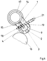
- the roller 9 is in contact with two adjacent rollers 14, 16.
- the bracket 1 receiving the quick-release fastener 2 is arranged on the machine frame 21 in a first swivel joint 17, which in the present example is axially parallel to the roller 14.
- a second spring element 19 is supported on the holder 1 in a second swivel joint 18 to the machine frame 21.
- the spring force of the quick-release fastener 2 is directed essentially in the direction of the nip, which is formed by the rollers 9 and 14.
- each fast-lockable bearing is open, so that there is sufficient space for inserting the roller 9.
- the quick-release fastener 2 is pivoted manually by preferably 90 ° in the direction of rotation 6 around the screw-in element 3.
- the roller 9 is inserted into the holder 1 and bears against the first adjacent roller 14.
- guide surfaces 20 arranged on the holder 1 are advantageous.
- the quick fastener 2 is in the corresponding Direction of rotation 6 pivots so that the centering 10 is in contact with the outer ring of the bearing 7 and the roller bearing is thus locked.
- the quick-release fastener 2 is raised against the spring action over the bearing 7 and centers the roller 9 over the bearing 7.
- screw-in element 3 By means of screw-in element 3, the contact pressure and thus the roller strip between the rollers 9, 14 can be adjusted before or after inserting the roller 9.
- the same setting values of the roll strip can always be restored to the original position.
- the screw-in element 3 is coupled to a sleeve 15, this is moved in the linear direction 6 when the contact pressure is set, and thus the spring element 4 is compressed or relaxed.
- the roller 9 is assigned two adjacent rollers 14, 16, the quick-lockable bearing is used analogously.
- the holder 1 is additionally pivotable in the first swivel joint 17 on the machine frame 21.
- the second spring element 19 presses the roller 9, which has already been pressed onto the first adjacent roller 14, against the second adjacent roller 16.
- the roller 9 can rest with its bearing 7 on a guide surface 20.
- the centering 10 can also be designed as a ball catch or with a curvature for receiving the bearing.
Landscapes
- Engineering & Computer Science (AREA)
- General Engineering & Computer Science (AREA)
- Mechanical Engineering (AREA)
- Inking, Control Or Cleaning Of Printing Machines (AREA)
- Rolls And Other Rotary Bodies (AREA)
- Rotary Presses (AREA)
- Centrifugal Separators (AREA)
- Separation Using Semi-Permeable Membranes (AREA)
- Pyrrole Compounds (AREA)
Applications Claiming Priority (2)
| Application Number | Priority Date | Filing Date | Title |
|---|---|---|---|
| DE19511710A DE19511710C1 (de) | 1995-03-30 | 1995-03-30 | Einseitig offene Lagerung für rotationssymmetrische Bauteile, vorzugsweise für Walzenzapfen in Druckmaschinen |
| DE19511710 | 1995-03-30 |
Publications (3)
| Publication Number | Publication Date |
|---|---|
| EP0734857A2 true EP0734857A2 (fr) | 1996-10-02 |
| EP0734857A3 EP0734857A3 (fr) | 1996-10-09 |
| EP0734857B1 EP0734857B1 (fr) | 1999-05-06 |
Family
ID=7758181
Family Applications (1)
| Application Number | Title | Priority Date | Filing Date |
|---|---|---|---|
| EP96104633A Expired - Lifetime EP0734857B1 (fr) | 1995-03-30 | 1996-03-23 | Palier pour éléments cylindriques |
Country Status (5)
| Country | Link |
|---|---|
| US (1) | US5683202A (fr) |
| EP (1) | EP0734857B1 (fr) |
| JP (1) | JPH08277834A (fr) |
| AT (1) | ATE179653T1 (fr) |
| DE (2) | DE19511710C1 (fr) |
Cited By (4)
| Publication number | Priority date | Publication date | Assignee | Title |
|---|---|---|---|---|
| EP0911158A3 (fr) * | 1997-10-21 | 1999-11-03 | Valmet Rotomec s.p.a. | Dispositif pour maintenir et enlever un cylindre d'impression rotatif sur des supports |
| WO2001038093A1 (fr) * | 1999-11-26 | 2001-05-31 | Koenig & Bauer Aktiengesellschaft | Support pour cylindre d'une presse d'impression rotative |
| CN103381697A (zh) * | 2012-05-02 | 2013-11-06 | 海德堡印刷机械股份公司 | 用于印刷机的辊锁 |
| DE102022105837A1 (de) | 2021-04-19 | 2022-10-20 | Heidelberger Druckmaschinen Aktiengesellschaft | Walzenschloss für eine Walze einer Druckmaschine |
Families Citing this family (18)
| Publication number | Priority date | Publication date | Assignee | Title |
|---|---|---|---|---|
| CA2118048C (fr) * | 1994-09-30 | 2003-04-08 | James W. Schumm | Amplification multiplex de locus de sequences courtes repetees en tandem |
| US5994062A (en) | 1995-10-02 | 1999-11-30 | The United States Of America As Represented By The Department Of Health And Human Services | Epithelial protein and DNA thereof for use in early cancer detection |
| US6140305A (en) * | 1996-04-04 | 2000-10-31 | Bio-Rad Laboratories, Inc. | Hereditary hemochromatosis gene products |
| DE19719305A1 (de) * | 1997-05-07 | 1998-11-12 | Roland Man Druckmasch | Lageranordnung für eine Walze eines Farb- oder Feuchtwerkes |
| US6130042A (en) * | 1998-03-05 | 2000-10-10 | The United States Of America As Represented By The Department Of Health And Human Services | Compositions and methods for diagnosing periodontal disease |
| DE10111068B4 (de) * | 2000-04-07 | 2018-01-18 | Heidelberger Druckmaschinen Ag | Walzenschloss zum lösbaren Befestigen einer Walze in einer Druckmaschine |
| US20040023237A1 (en) * | 2001-11-26 | 2004-02-05 | Perelegen Sciences Inc. | Methods for genomic analysis |
| JP4068063B2 (ja) * | 2001-12-06 | 2008-03-26 | ケーニツヒ ウント バウエル アクチエンゲゼルシヤフト | 印刷機のローラを調節するための装置 |
| JP4171210B2 (ja) | 2001-12-17 | 2008-10-22 | 株式会社小森コーポレーション | 印刷機のローラ保持装置 |
| EP1568494B1 (fr) * | 2004-02-27 | 2012-11-28 | Müller Martini Holding AG | Dispositif pour réaliser des impression à format variable dans des machines à imprimer offset |
| JP4814309B2 (ja) | 2005-03-30 | 2011-11-16 | ゴス インターナショナル アメリカス インコーポレイテッド | ブランケット胴胴抜き支持面を有する印刷ユニット |
| WO2006104830A2 (fr) | 2005-03-30 | 2006-10-05 | Goss International Americas, Inc. | Presse a imprimer offset sur papier sans fin pourvue d'une lame plieuse articulee |
| US7775159B2 (en) | 2005-03-30 | 2010-08-17 | Goss International Americas, Inc. | Cantilevered blanket cylinder lifting mechanism |
| CN101208201B (zh) | 2005-03-30 | 2011-10-05 | 高斯国际美洲公司 | 具有自动装版的卷筒纸胶印印刷机 |
| JP4829291B2 (ja) | 2005-04-11 | 2011-12-07 | ゴス インターナショナル アメリカス インコーポレイテッド | 単一モータ駆動を用いて自動プレーティングを可能にする印刷ユニット |
| DE102005056649B3 (de) * | 2005-11-25 | 2007-05-31 | Langenstein & Schemann Gmbh | Vorrichtung zum Halten von wenigstens zwei Walzen einer Walzmaschine und Walzmaschine |
| CN112918085B (zh) * | 2021-01-22 | 2022-06-03 | 浙江荣大时尚科技有限公司 | 一种热转印机 |
| CN115815679B (zh) * | 2022-11-16 | 2024-11-19 | 苏州中航盛世刀辊制造有限公司 | 一种预防跳刀的加压机构 |
Family Cites Families (12)
| Publication number | Priority date | Publication date | Assignee | Title |
|---|---|---|---|---|
| GB191201942A (en) * | 1912-01-24 | 1912-12-05 | Goss Printing Press Co England | Improvements in Shaft Bearings particularly adapted for use with Inking Rollers of Printing Presses. |
| US3167010A (en) * | 1962-06-13 | 1965-01-26 | Wood Newspaper Mach Corp | Adjustable press roller sockets |
| US3480225A (en) * | 1968-04-02 | 1969-11-25 | Alexeff Snyder Ets | Self-locking chuck for roll shafts |
| US4030704A (en) * | 1975-07-25 | 1977-06-21 | Carl Beierle | Wire or cable reel support |
| IT1160413B (it) * | 1978-12-28 | 1987-03-11 | Cigardi Omc Sa | Dispositivo di bagnotura perfezionato, ad acqua ed a miscela acqua-alcool, applicabile su macchine da stampa offset |
| US4575286A (en) * | 1984-11-19 | 1986-03-11 | The Gleason Works | Gear cutter assembly |
| US4759286A (en) * | 1987-05-27 | 1988-07-26 | Am International, Inc. | Mounting bracket for printing or duplicating machine roller |
| IT1226463B (it) * | 1988-07-27 | 1991-01-16 | Sted Eng Srl | Aggancio rapido per la sostituzione di rulli |
| DE4216781C2 (de) * | 1992-05-21 | 1995-08-03 | Heidelberger Druckmasch Ag | Vorrichtung zur Aufnahme von Rotationskörperzapfen |
| US5241905A (en) * | 1992-10-27 | 1993-09-07 | Heidelberg Harris Inc. | Printing unit with releasable bearing clamp |
| DE4240487C1 (de) * | 1992-12-02 | 1993-12-09 | Roland Man Druckmasch | Walzenlagerung |
| DE4243657C2 (de) * | 1992-12-23 | 1997-05-07 | Heidelberger Druckmasch Ag | Walzenlager für Walzen in Druckwerken einer Druckmaschine |
-
1995
- 1995-03-30 DE DE19511710A patent/DE19511710C1/de not_active Expired - Fee Related
-
1996
- 1996-03-23 DE DE59601800T patent/DE59601800D1/de not_active Expired - Fee Related
- 1996-03-23 AT AT96104633T patent/ATE179653T1/de not_active IP Right Cessation
- 1996-03-23 EP EP96104633A patent/EP0734857B1/fr not_active Expired - Lifetime
- 1996-03-29 US US08/624,172 patent/US5683202A/en not_active Expired - Fee Related
- 1996-04-01 JP JP8079238A patent/JPH08277834A/ja active Pending
Cited By (6)
| Publication number | Priority date | Publication date | Assignee | Title |
|---|---|---|---|---|
| EP0911158A3 (fr) * | 1997-10-21 | 1999-11-03 | Valmet Rotomec s.p.a. | Dispositif pour maintenir et enlever un cylindre d'impression rotatif sur des supports |
| WO2001038093A1 (fr) * | 1999-11-26 | 2001-05-31 | Koenig & Bauer Aktiengesellschaft | Support pour cylindre d'une presse d'impression rotative |
| US6712000B1 (en) | 1999-11-26 | 2004-03-30 | Koenig & Bauer Aktiengesellschaft | Arrangement of bearings pertaining to a cylinder of a rotary printing press |
| CN103381697A (zh) * | 2012-05-02 | 2013-11-06 | 海德堡印刷机械股份公司 | 用于印刷机的辊锁 |
| CN103381697B (zh) * | 2012-05-02 | 2016-08-03 | 海德堡印刷机械股份公司 | 用于印刷机的辊锁 |
| DE102022105837A1 (de) | 2021-04-19 | 2022-10-20 | Heidelberger Druckmaschinen Aktiengesellschaft | Walzenschloss für eine Walze einer Druckmaschine |
Also Published As
| Publication number | Publication date |
|---|---|
| EP0734857B1 (fr) | 1999-05-06 |
| ATE179653T1 (de) | 1999-05-15 |
| US5683202A (en) | 1997-11-04 |
| JPH08277834A (ja) | 1996-10-22 |
| DE19511710C1 (de) | 1996-04-11 |
| DE59601800D1 (de) | 1999-06-10 |
| EP0734857A3 (fr) | 1996-10-09 |
Similar Documents
| Publication | Publication Date | Title |
|---|---|---|
| EP0734857A2 (fr) | Palier pour éléments cylindriques | |
| EP0741017B1 (fr) | Support de palier pour des extrémités d'arbres | |
| DE19944936A1 (de) | Vorrichtung zur Voreinstellung der Druckanstellung un der Druckabstellung von Zylindern eines Druckwerks in einer Rotationsdruckmaschine | |
| DE2030040C3 (de) | Greifeinrichtung an Zylindern bogenverarbeüender Maschinen | |
| EP0493772B1 (fr) | Dispositif de serrage et dispositif tendeur | |
| WO2001021333A2 (fr) | Dispositif pour installer et retirer un palier d'un cylindre d'appui | |
| DE4128994A1 (de) | Klemm- und spanneinrichtung | |
| DE3409479C2 (fr) | ||
| DE19526898A1 (de) | Verriegelungsvorrichtung für Fluiddruckzylinder | |
| DE10111068B4 (de) | Walzenschloss zum lösbaren Befestigen einer Walze in einer Druckmaschine | |
| DE4238343C2 (de) | Spannvorrichtung für ein Klischee | |
| DE4422612C1 (de) | Wascheinrichtung für Farbwerke von Druckmaschinen | |
| DE4400563A1 (de) | Walze in einem Farbwerk oder Feuchtwerk einer Rotationsdruckmaschine | |
| EP0795401B1 (fr) | Dispositif pour raccorder des tuyaux d'une façon détachable dans une machine d'impression | |
| DE69025835T2 (de) | Plattenaufwicklungsvorrichtung | |
| DE3115270C2 (de) | Druckplatten-Haltevorrichtung | |
| DE10003937A1 (de) | Vorrichtung zum Befestigen von biegsamen Druckformen | |
| EP0534214B1 (fr) | Procédé et dispositif pour la correction de divergences trapézoidales des repères | |
| EP0774353B1 (fr) | Machine d'impression offset | |
| DE4240487C1 (de) | Walzenlagerung | |
| DE4226192C2 (de) | Verfahren und Vorrichtung zur Korrektur trapezartiger Passerabweichungen | |
| DE102007059169B4 (de) | Vorrichtung zur statischen Positionierug von Einrichtungen | |
| EP0786338A1 (fr) | Dispositif pour la mise en pression et hors pression d'un cylindre | |
| DE10127133A1 (de) | Zylinder mit einer Klemmeinrichtung in einer Druckmaschine | |
| DE10024331A1 (de) | Verfahren und Vorrichtungen zum Klemmen und/oder Spannen |
Legal Events
| Date | Code | Title | Description |
|---|---|---|---|
| PUAI | Public reference made under article 153(3) epc to a published international application that has entered the european phase |
Free format text: ORIGINAL CODE: 0009012 |
|
| PUAL | Search report despatched |
Free format text: ORIGINAL CODE: 0009013 |
|
| 17P | Request for examination filed |
Effective date: 19960412 |
|
| AK | Designated contracting states |
Kind code of ref document: A2 Designated state(s): AT BE CH DE FR GB IT LI NL SE |
|
| AK | Designated contracting states |
Kind code of ref document: A3 Designated state(s): AT BE CH DE FR GB IT LI NL SE |
|
| 17Q | First examination report despatched |
Effective date: 19970403 |
|
| GRAG | Despatch of communication of intention to grant |
Free format text: ORIGINAL CODE: EPIDOS AGRA |
|
| GRAG | Despatch of communication of intention to grant |
Free format text: ORIGINAL CODE: EPIDOS AGRA |
|
| GRAH | Despatch of communication of intention to grant a patent |
Free format text: ORIGINAL CODE: EPIDOS IGRA |
|
| GRAH | Despatch of communication of intention to grant a patent |
Free format text: ORIGINAL CODE: EPIDOS IGRA |
|
| ITF | It: translation for a ep patent filed | ||
| GRAA | (expected) grant |
Free format text: ORIGINAL CODE: 0009210 |
|
| AK | Designated contracting states |
Kind code of ref document: B1 Designated state(s): AT BE CH DE FR GB IT LI NL SE |
|
| PG25 | Lapsed in a contracting state [announced via postgrant information from national office to epo] |
Ref country code: NL Free format text: LAPSE BECAUSE OF FAILURE TO SUBMIT A TRANSLATION OF THE DESCRIPTION OR TO PAY THE FEE WITHIN THE PRESCRIBED TIME-LIMIT Effective date: 19990506 |
|
| REF | Corresponds to: |
Ref document number: 179653 Country of ref document: AT Date of ref document: 19990515 Kind code of ref document: T |
|
| ET | Fr: translation filed | ||
| REG | Reference to a national code |
Ref country code: CH Ref legal event code: NV Representative=s name: E. BLUM & CO. PATENTANWAELTE Ref country code: CH Ref legal event code: EP |
|
| GBT | Gb: translation of ep patent filed (gb section 77(6)(a)/1977) |
Effective date: 19990507 |
|
| REF | Corresponds to: |
Ref document number: 59601800 Country of ref document: DE Date of ref document: 19990610 |
|
| PGFP | Annual fee paid to national office [announced via postgrant information from national office to epo] |
Ref country code: DE Payment date: 20000224 Year of fee payment: 5 |
|
| PLBE | No opposition filed within time limit |
Free format text: ORIGINAL CODE: 0009261 |
|
| STAA | Information on the status of an ep patent application or granted ep patent |
Free format text: STATUS: NO OPPOSITION FILED WITHIN TIME LIMIT |
|
| PG25 | Lapsed in a contracting state [announced via postgrant information from national office to epo] |
Ref country code: BE Free format text: LAPSE BECAUSE OF NON-PAYMENT OF DUE FEES Effective date: 20000331 |
|
| 26N | No opposition filed | ||
| BERE | Be: lapsed |
Owner name: MAN ROLAND DRUCKMASCHINEN A.G. Effective date: 20000331 |
|
| PG25 | Lapsed in a contracting state [announced via postgrant information from national office to epo] |
Ref country code: DE Free format text: LAPSE BECAUSE OF NON-PAYMENT OF DUE FEES Effective date: 20020101 |
|
| REG | Reference to a national code |
Ref country code: GB Ref legal event code: IF02 |
|
| PGFP | Annual fee paid to national office [announced via postgrant information from national office to epo] |
Ref country code: CH Payment date: 20030218 Year of fee payment: 8 |
|
| PGFP | Annual fee paid to national office [announced via postgrant information from national office to epo] |
Ref country code: GB Payment date: 20030226 Year of fee payment: 8 |
|
| PGFP | Annual fee paid to national office [announced via postgrant information from national office to epo] |
Ref country code: SE Payment date: 20030304 Year of fee payment: 8 Ref country code: AT Payment date: 20030304 Year of fee payment: 8 |
|
| PGFP | Annual fee paid to national office [announced via postgrant information from national office to epo] |
Ref country code: FR Payment date: 20030314 Year of fee payment: 8 |
|
| PG25 | Lapsed in a contracting state [announced via postgrant information from national office to epo] |
Ref country code: GB Free format text: LAPSE BECAUSE OF NON-PAYMENT OF DUE FEES Effective date: 20040323 Ref country code: AT Free format text: LAPSE BECAUSE OF NON-PAYMENT OF DUE FEES Effective date: 20040323 |
|
| PG25 | Lapsed in a contracting state [announced via postgrant information from national office to epo] |
Ref country code: SE Free format text: LAPSE BECAUSE OF NON-PAYMENT OF DUE FEES Effective date: 20040324 |
|
| PG25 | Lapsed in a contracting state [announced via postgrant information from national office to epo] |
Ref country code: LI Free format text: LAPSE BECAUSE OF NON-PAYMENT OF DUE FEES Effective date: 20040331 Ref country code: CH Free format text: LAPSE BECAUSE OF NON-PAYMENT OF DUE FEES Effective date: 20040331 |
|
| EUG | Se: european patent has lapsed | ||
| GBPC | Gb: european patent ceased through non-payment of renewal fee |
Effective date: 20040323 |
|
| REG | Reference to a national code |
Ref country code: CH Ref legal event code: PL |
|
| PG25 | Lapsed in a contracting state [announced via postgrant information from national office to epo] |
Ref country code: FR Free format text: LAPSE BECAUSE OF NON-PAYMENT OF DUE FEES Effective date: 20041130 |
|
| REG | Reference to a national code |
Ref country code: FR Ref legal event code: ST |
|
| PG25 | Lapsed in a contracting state [announced via postgrant information from national office to epo] |
Ref country code: IT Free format text: LAPSE BECAUSE OF NON-PAYMENT OF DUE FEES;WARNING: LAPSES OF ITALIAN PATENTS WITH EFFECTIVE DATE BEFORE 2007 MAY HAVE OCCURRED AT ANY TIME BEFORE 2007. THE CORRECT EFFECTIVE DATE MAY BE DIFFERENT FROM THE ONE RECORDED. Effective date: 20050323 |