EP0741017B1 - Support de palier pour des extrémités d'arbres - Google Patents
Support de palier pour des extrémités d'arbres Download PDFInfo
- Publication number
- EP0741017B1 EP0741017B1 EP96104695A EP96104695A EP0741017B1 EP 0741017 B1 EP0741017 B1 EP 0741017B1 EP 96104695 A EP96104695 A EP 96104695A EP 96104695 A EP96104695 A EP 96104695A EP 0741017 B1 EP0741017 B1 EP 0741017B1
- Authority
- EP
- European Patent Office
- Prior art keywords
- cover part
- support shell
- bearing
- lever
- shell
- Prior art date
- Legal status (The legal status is an assumption and is not a legal conclusion. Google has not performed a legal analysis and makes no representation as to the accuracy of the status listed.)
- Expired - Lifetime
Links
- 230000006835 compression Effects 0.000 claims description 4
- 238000007906 compression Methods 0.000 claims description 4
- 238000007774 anilox coating Methods 0.000 description 8
- 238000010276 construction Methods 0.000 description 1
- NJPPVKZQTLUDBO-UHFFFAOYSA-N novaluron Chemical compound C1=C(Cl)C(OC(F)(F)C(OC(F)(F)F)F)=CC=C1NC(=O)NC(=O)C1=C(F)C=CC=C1F NJPPVKZQTLUDBO-UHFFFAOYSA-N 0.000 description 1
- 230000000149 penetrating effect Effects 0.000 description 1
Images


Classifications
-
- F—MECHANICAL ENGINEERING; LIGHTING; HEATING; WEAPONS; BLASTING
- F16—ENGINEERING ELEMENTS AND UNITS; GENERAL MEASURES FOR PRODUCING AND MAINTAINING EFFECTIVE FUNCTIONING OF MACHINES OR INSTALLATIONS; THERMAL INSULATION IN GENERAL
- F16C—SHAFTS; FLEXIBLE SHAFTS; ELEMENTS OR CRANKSHAFT MECHANISMS; ROTARY BODIES OTHER THAN GEARING ELEMENTS; BEARINGS
- F16C13/00—Rolls, drums, discs, or the like; Bearings or mountings therefor
- F16C13/02—Bearings
-
- B—PERFORMING OPERATIONS; TRANSPORTING
- B41—PRINTING; LINING MACHINES; TYPEWRITERS; STAMPS
- B41F—PRINTING MACHINES OR PRESSES
- B41F13/00—Common details of rotary presses or machines
- B41F13/08—Cylinders
- B41F13/20—Supports for bearings or supports for forme, offset, or impression cylinders
-
- F—MECHANICAL ENGINEERING; LIGHTING; HEATING; WEAPONS; BLASTING
- F16—ENGINEERING ELEMENTS AND UNITS; GENERAL MEASURES FOR PRODUCING AND MAINTAINING EFFECTIVE FUNCTIONING OF MACHINES OR INSTALLATIONS; THERMAL INSULATION IN GENERAL
- F16C—SHAFTS; FLEXIBLE SHAFTS; ELEMENTS OR CRANKSHAFT MECHANISMS; ROTARY BODIES OTHER THAN GEARING ELEMENTS; BEARINGS
- F16C35/00—Rigid support of bearing units; Housings, e.g. caps, covers
Definitions
- the invention relates to a holder for mounted on shaft journals Bearings, preferably for printing and inking roller bearings of printing presses, consisting of a lower frame fixed Carrier shell and from a pivotally connected to this Cover part that with a lower, forming an actuating part Lever is provided in the open position of the lid part protrudes in or over the tray so that it passes through Lowering of the abutting against it, placed on the shaft journal Bearing the cover part in its closed position in the carrying shell pivoted, in which this with its circular arc curved inner side lies close to the bearing and that in his folded onto the bearing inserted in the tray Locked position is lockable.
- a holder of this type is known from EP 0 438 733 B1 it allows shaft journals to be placed on these bearings to be used in warehouse brackets by automated devices and digging out of these without manual work to Opening and closing the brackets are necessary.
- This well-known Bracket is relatively expensive because this is pivotally mounted on the support shell two cover parts are in their closed position with the closed position their faces face each other and with a connecting these Locking device are provided.
- the object of the invention is a simpler holder to create the type specified above.
- a single Cover part pivotably provided with a locking lever is that has an end hook-shaped part that with hooked an abutment of the support shell, and that one the locking lever automatically pivoting device provided is.
- the holder according to the invention is characterized by a simple Construction, since this is only one hinged cover part possesses, the free end easily and quickly for fixation the bearing can be locked with the support shell.
- the locking lever expediently exists automatically pivoting device from a loading in the closing direction
- Compression spring which is driven by a driven plunger o. Like. Can be pressed into its open position.
- the compression spring can consist of disc springs. By a pack of disc springs a high compressive force can be achieved with only a small spring height produce.
- driven plunger the piston rod of a pneumatic cylinder is.
- the abutment can be made from a pin behind the support shell consist.
- the hook-shaped part preferably has one wedge-shaped beveled flank that is exciting on the abutment attacks. In this way, the bearing is held without play ensured.
- a flexographic printing press 1 has a central impression cylinder 2 provided, on which the printing rollers 4 of all printing units are employable.
- the pressure cylinder 4 and those adjustable to it Anilox rollers 5 are supported in pedestals that are on the frame connected printing unit consoles 3 are displaceable.
- Flexographic printing machines of this type are, for example, from DE-C-29 41 521 and known from EP-B-0 438 733.
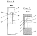
- each anilox roller bearing block 6 provided with a support shell 7, which is approximately semi-cylindrical Owns the wall.
- this carrier shell 7 that is on the shaft journal 8 of the anilox roller 9 mounted bearings 10 can be used at which can be a roller bearing, the outer diameter corresponds to the radius of curvature of the wall of the support shell 7.
- the anilox roller bearing block has on the left side of the carrier shell 7 6 a bearing block 11 for the cover part 12.
- the cover part 12 is provided with forked bearing legs 13, 14, wherein the bearing legs and the bearing block 11 with aligned holes are provided, in which a bearing block is held or arranged is.
- the cover part 12 is laterally connected to a lever 15, which in the manner shown in FIGS. 2, 3 and 5 in a lateral recess of the cover part.
- the lever 15 is provided with a bore 16 with which it supports the bearing pin 16 spreads. In addition, it is connected by a screw bolt 17 screwed to the cover part.
- the anilox roller bearing block 6 is also provided with a lateral recess 18 into which the lever 15 after inserting the bearing 10 into the bearing shell 7 without hindrance can immerse.
- the cover part is cylindrical-shaped on its underside Provide recess 20, the radius of curvature of the Diameter of the bearing 10 corresponds.
- a locking lever 21 is pivotable at the end of the cover part stored.
- the flanks are for mounting the locking lever 21 the groove 22 penetrating holes are provided, in which the the lever 21 bearing pin 23 is supported.
- the lever 21 is designed as an angle lever, the shorter angled one Leg 25 projects beyond a hole in the cover part 12.
- a plate spring assembly 26 used, of which the the lower plate spring is supported on an annular step of the bore 27.
- the holes in the disc springs are interspersed with an upper one widened head provided bolt 28, the upper Disc spring is supported on the ring step formed by the head.
- the head of the bolt 28 is supported in the 2 and 3 visible way on the lower flank of the shorter one Lever 25 off, so that the Belleville spring assembly 26 strives to To pivot lever 21 into its closed position shown in FIG. 3.
- the lever 21 is hook-shaped at its free lower end Provide part 30, which can be seen in Fig. 3 Locking position one in a groove of the anilox roller bearing block 6 held bolts 31 forming an abutment engages behind.
- a holder 33 for a pneumatic cylinder 34 placed, the piston rod 35 on the shorter Lever arm 25 of the locking lever 21 supports. Will the Pneumatic cylinder 34 pressurized, drives the piston rod 35 and pivots the locking lever 31 against the force of the plate spring assembly 26 into that shown in FIG. 2 unlocked position.
- the cover part 12 is provided with a stop 38 with which this in its open position shown in FIG. 2 can support on the anilox roller pedestal 6.
Landscapes
- Engineering & Computer Science (AREA)
- General Engineering & Computer Science (AREA)
- Mechanical Engineering (AREA)
- Rotary Presses (AREA)
- Motor Power Transmission Devices (AREA)
- Soil Working Implements (AREA)
- Inking, Control Or Cleaning Of Printing Machines (AREA)
- Rolls And Other Rotary Bodies (AREA)
Claims (6)
- Support pour des paliers disposés sur des tourillons d'arbre, de préférence pour des paliers de rouleaux d'impression et d'encrage de machines d'impression, constitué d'une coupelle de support inférieure, solidaire du châssis et d'une partie de couvercle reliée d'une manière pivotante à celle-ci qui est pourvue d'un levier inférieur, formant une pièce d'actionnement qui, dans la position ouverte de la partie de couvercle, fait saillie dans ou au-delà de la coupelle de support de telle manière qu'il fait pivoter, par un abaissement du palier heurtant celle-ci, disposé sur le tourillon d'arbre, dans la coupelle de support, la partie de couvercle dans sa position de fermeture dans laquelle celle-ci, avec son côté intérieur courbé en forme d'arc de cercle, s'applique étroitement au palier et qui peut être verrouillée dans sa position de fermeture rabattue sur le palier placé dans la coupelle de support, caractérisé en ce qu'une seule partie de couvercle (12) est reliée d'une manière pivotante à un levier de verrouillage (21) qui présente une partie (30) en forme de crochet au côté de l'extrémité qui s'accroche à une butée (31) de la coupelle de support (6), et en ce qu'il est prévu un dispositif faisant pivoter automatiquement le levier de verrouillage (21).
- Support selon la revendication 1, caractérisé en ce que le dispositif faisant pivoter le levier de verrouillage (21) est constitué d'un ressort de pression (26) sollicitant celui-ci dans la direction de fermeture qui peut être poussé par un poussoir entraíné (35) ou analogue dans sa position d'ouverture.
- Support selon la revendication 2, caractérisé en ce que le ressort de pression est constitué d'un groupe de ressorts à disques (26).
- Support selon la revendication 2 ou 3, caractérisé en ce que le poussoir entraíné est la tige de piston (35) d'un vérin pneumatique (34).
- Support selon l'une des revendications 1 à 4, caractérisé en ce que la butée est constituée d'un boulon (31) derrière lequel on peut passer de la coupelle de support.
- Support selon l'une des revendications 1 à 5, caractérisé en ce que la partie en forme de crochet (30) possède un flanc conique qui s'applique sous tension à la butée (31).
Applications Claiming Priority (2)
| Application Number | Priority Date | Filing Date | Title |
|---|---|---|---|
| DE19516455 | 1995-05-04 | ||
| DE19516455A DE19516455A1 (de) | 1995-05-04 | 1995-05-04 | Halterung für auf Wellenzapfen aufgesetzte Lager |
Publications (3)
| Publication Number | Publication Date |
|---|---|
| EP0741017A2 EP0741017A2 (fr) | 1996-11-06 |
| EP0741017A3 EP0741017A3 (fr) | 1997-04-23 |
| EP0741017B1 true EP0741017B1 (fr) | 1999-05-26 |
Family
ID=7761121
Family Applications (1)
| Application Number | Title | Priority Date | Filing Date |
|---|---|---|---|
| EP96104695A Expired - Lifetime EP0741017B1 (fr) | 1995-05-04 | 1996-03-25 | Support de palier pour des extrémités d'arbres |
Country Status (4)
| Country | Link |
|---|---|
| US (1) | US5669302A (fr) |
| EP (1) | EP0741017B1 (fr) |
| DE (2) | DE19516455A1 (fr) |
| ES (1) | ES2131886T3 (fr) |
Families Citing this family (22)
| Publication number | Priority date | Publication date | Assignee | Title |
|---|---|---|---|---|
| EP0881071A3 (fr) * | 1996-06-12 | 1998-12-09 | Fischer & Krecke Gmbh & Co. | Machine d'impression |
| DE19719305A1 (de) * | 1997-05-07 | 1998-11-12 | Roland Man Druckmasch | Lageranordnung für eine Walze eines Farb- oder Feuchtwerkes |
| IT1299666B1 (it) * | 1998-05-05 | 2000-03-24 | Uteco Spa Roto Flexo & Convert | Macchina rotativa flessografica a tamburo centrale a piu' colori |
| DE19821286C2 (de) * | 1998-05-12 | 2002-03-21 | Windmoeller & Hoelscher | Halterung für auf Wellenzapfen aufgesetzte Lager |
| ATE254537T1 (de) * | 1999-10-11 | 2003-12-15 | Gidue S P A | Druckeinheit mit einem druckzylinder mit vereinfachten entfernung und verriegelung |
| EP1568494B1 (fr) * | 2004-02-27 | 2012-11-28 | Müller Martini Holding AG | Dispositif pour réaliser des impression à format variable dans des machines à imprimer offset |
| ITFI20040139A1 (it) * | 2004-06-18 | 2004-09-18 | O M Futura S P A | Apparato di supporto per rulli goffratori e metodo per la sostituzione degli stessi |
| ITVR20040141A1 (it) * | 2004-09-10 | 2004-12-10 | Valentini Maria Grazia | Dispositivo di supporto e ritenuta a rilascio per un mozzo di un cilindro per macchina da stampa. |
| ITMI20042038A1 (it) * | 2004-10-26 | 2005-01-26 | Paper Converting Machine Co | Gruppo goffratore per materiale in foglio |
| DE102008025996A1 (de) * | 2008-05-29 | 2009-12-24 | Windmöller & Hölscher Kg | Druckmaschine mit mehreren Farbwerken |
| FR2934199B1 (fr) * | 2008-07-25 | 2011-07-15 | Cuir Ccm | Machine d'impression equipee d'un cylindre trame amovible |
| DE102009028201B4 (de) | 2009-08-04 | 2016-06-09 | Kba-Meprint Ag | Druckmaschine und ein Verfahren zur Handhabung von Zylindern |
| DE102009028199A1 (de) * | 2009-08-04 | 2011-02-17 | Kba-Metronic Aktiengesellschaft | Lageraufnahme eines Lagers eines Zylinderzapfens und ein Verfahren zum Schließen und Verriegeln einer Lageraufnahme |
| DE102009028214B4 (de) | 2009-08-04 | 2016-06-02 | Kba-Meprint Ag | Positioniervorrichtung zweier Zylinder und ein Verfahren zur Positionierung von Zylindern |
| DE102009028208B4 (de) | 2009-08-04 | 2017-04-13 | Koenig & Bauer Ag | Koppelvorrichtung eines Zylinders einer Druckmaschine und ein Verfahren zum Ankoppeln eines Zylinders einer Druckmaschine |
| ITFI20120070A1 (it) * | 2012-04-03 | 2013-10-04 | Futura Spa | Gruppo per la goffratura di materiale cartaceo. |
| CN104944189A (zh) * | 2015-06-16 | 2015-09-30 | 安徽明诚塑业有限公司 | 一种全自动接料彩印机转辊固定连接装置 |
| CN104986601A (zh) * | 2015-06-16 | 2015-10-21 | 安徽明诚塑业有限公司 | 一种彩印机的全自动接料装置 |
| DE102016206764A1 (de) * | 2016-04-21 | 2017-10-26 | Heidelberger Druckmaschinen Ag | Bearbeitungsmaschine mit freigebbarem Bearbeitungszylinder |
| CN106313908A (zh) * | 2016-08-22 | 2017-01-11 | 厦门顶尖电子有限公司 | 热敏打印机芯胶辊轴与主支架开口轴承的配合结构 |
| CN108099364A (zh) * | 2017-12-08 | 2018-06-01 | 青州蒙特机械有限公司 | 柔版印刷机用版辊自动锁定装置 |
| NL2025770B1 (en) | 2020-06-08 | 2022-01-28 | Marel Further Proc Bv | A rotary mould drum system configured for use in an installation for moulding food products from a pumpable foodmass |
Family Cites Families (10)
| Publication number | Priority date | Publication date | Assignee | Title |
|---|---|---|---|---|
| US1179797A (en) * | 1915-03-23 | 1916-04-18 | Thomas Bell | Distributer-roller bearing for printing-presses. |
| US1379818A (en) * | 1921-01-28 | 1921-05-31 | Hinnekens Florent | Bearing |
| DE1254112B (de) * | 1963-02-22 | 1967-11-16 | Kleinewefers Soehne J | Druckwalzen-Lagergehaeuse fuer Rouleaux-Druckmaschine |
| DE2941521C2 (de) * | 1979-10-12 | 1982-11-25 | Windmöller & Hölscher, 4540 Lengerich | Verfahren zum Austauschen der Formzylinder einer Flexodruckmaschine |
| US4528907A (en) * | 1984-06-22 | 1985-07-16 | Norwood Marking & Equipment Co., Inc. | Print head with dual exchangeable hot inking rolls |
| US4760789A (en) * | 1986-07-10 | 1988-08-02 | Am International, Inc. | Adjustable roller system for printing or duplicating machines |
| DE4001736A1 (de) * | 1990-01-22 | 1991-07-25 | Windmoeller & Hoelscher | Lagerhalterung fuer auf wellenzapfen aufgesetzte lager |
| DE4041497A1 (de) * | 1990-12-22 | 1992-06-25 | Roland Man Druckmasch | Lagerung fuer einen druckwerkzylinder |
| DE4109888A1 (de) * | 1991-03-26 | 1992-10-01 | Leybold Ag | Vorrichtung zur halterung und fuehrung einer achse oder welle oder eines lagerrings |
| JP2597629Y2 (ja) * | 1991-10-11 | 1999-07-12 | 株式会社小森コーポレーション | 印刷機のローラ保持装置 |
-
1995
- 1995-05-04 DE DE19516455A patent/DE19516455A1/de not_active Ceased
-
1996
- 1996-03-25 ES ES96104695T patent/ES2131886T3/es not_active Expired - Lifetime
- 1996-03-25 DE DE59601977T patent/DE59601977D1/de not_active Expired - Lifetime
- 1996-03-25 EP EP96104695A patent/EP0741017B1/fr not_active Expired - Lifetime
- 1996-05-02 US US08/641,904 patent/US5669302A/en not_active Expired - Lifetime
Also Published As
| Publication number | Publication date |
|---|---|
| EP0741017A3 (fr) | 1997-04-23 |
| DE19516455A1 (de) | 1996-11-07 |
| EP0741017A2 (fr) | 1996-11-06 |
| ES2131886T3 (es) | 1999-08-01 |
| US5669302A (en) | 1997-09-23 |
| DE59601977D1 (de) | 1999-07-01 |
Similar Documents
| Publication | Publication Date | Title |
|---|---|---|
| EP0741017B1 (fr) | Support de palier pour des extrémités d'arbres | |
| EP0734857B1 (fr) | Palier pour éléments cylindriques | |
| DE3731684A1 (de) | Aufspannvorrichtung | |
| DE19944936A1 (de) | Vorrichtung zur Voreinstellung der Druckanstellung un der Druckabstellung von Zylindern eines Druckwerks in einer Rotationsdruckmaschine | |
| DE4001736A1 (de) | Lagerhalterung fuer auf wellenzapfen aufgesetzte lager | |
| DE3440895A1 (de) | Farbwerk einer rotationsdruckmaschine, insbesondere offsetdruckmaschine | |
| AT392661B (de) | Presswalze, deren durchbiegung einstellbar ist | |
| DE4213663C2 (de) | Rakelbalken für ein Kurzfarbwerk einer Rollenrotationsdruckmaschine | |
| DE2029007C3 (de) | Vorrichtung zum Einstellen der Druckkraft einer in Haltern gelagerten Auftragwalze eines Feuchtwerkes einer Offsetdruckmaschine | |
| DE10127133C5 (de) | Zylinder mit einer Klemmeinrichtung in einer Druckmaschine | |
| DE4340482C2 (de) | Tiefdruckfarbwerk | |
| DE3526634A1 (de) | Vorrichtung zum anheben und verschieben von werkzeugen oder werkstuecken auf einem aufspanntisch | |
| DE2423504A1 (de) | Kalander, insbesondere zur bearbeitung von papierbahnen | |
| DE19821286C2 (de) | Halterung für auf Wellenzapfen aufgesetzte Lager | |
| DE3031150A1 (de) | Plattenklemmeinrichtung | |
| DE4240487C1 (de) | Walzenlagerung | |
| DE19931758C2 (de) | Trageeinrichtung zum Heben und Senken von Lasten | |
| DE3519293C2 (fr) | ||
| DE29803330U1 (de) | Hubvorrichtung | |
| DE10210561B4 (de) | Vorrichtung zum Einstellen und Halten der Abstände der Gummituchzylinder einer Mehrzahl von Druckwerken einer Satelliten- Bogenrotationsdruckeinheit zu einem gemeinsamen Gegendruckzylinder | |
| DE1952647C3 (de) | Anordnung zum Festlegen der Gelenkspindeln in einem Spindelstuhl | |
| DE69300437T2 (de) | Offsetdruckmaschine. | |
| EP1707361A2 (fr) | Rouleau applicateur pour un groupe d'impression offset | |
| DE2426327A1 (de) | Schraubenfederenden-schleifmaschine mit automatischer beschickungseinrichtung | |
| DE102006050569B3 (de) | Vorrichtung zum Umgang mit zylindrischen Großteilen, insbesondere zum Umgang mit Druckzylindern von Rollenoffestdruckmaschinen |
Legal Events
| Date | Code | Title | Description |
|---|---|---|---|
| PUAI | Public reference made under article 153(3) epc to a published international application that has entered the european phase |
Free format text: ORIGINAL CODE: 0009012 |
|
| AK | Designated contracting states |
Kind code of ref document: A2 Designated state(s): DE ES FR GB IT |
|
| PUAL | Search report despatched |
Free format text: ORIGINAL CODE: 0009013 |
|
| AK | Designated contracting states |
Kind code of ref document: A3 Designated state(s): DE ES FR GB IT |
|
| 17P | Request for examination filed |
Effective date: 19971023 |
|
| GRAG | Despatch of communication of intention to grant |
Free format text: ORIGINAL CODE: EPIDOS AGRA |
|
| GRAG | Despatch of communication of intention to grant |
Free format text: ORIGINAL CODE: EPIDOS AGRA |
|
| GRAH | Despatch of communication of intention to grant a patent |
Free format text: ORIGINAL CODE: EPIDOS IGRA |
|
| 17Q | First examination report despatched |
Effective date: 19980914 |
|
| GRAH | Despatch of communication of intention to grant a patent |
Free format text: ORIGINAL CODE: EPIDOS IGRA |
|
| GRAA | (expected) grant |
Free format text: ORIGINAL CODE: 0009210 |
|
| AK | Designated contracting states |
Kind code of ref document: B1 Designated state(s): DE ES FR GB IT |
|
| ITF | It: translation for a ep patent filed | ||
| REF | Corresponds to: |
Ref document number: 59601977 Country of ref document: DE Date of ref document: 19990701 |
|
| REG | Reference to a national code |
Ref country code: ES Ref legal event code: FG2A Ref document number: 2131886 Country of ref document: ES Kind code of ref document: T3 |
|
| GBT | Gb: translation of ep patent filed (gb section 77(6)(a)/1977) |
Effective date: 19990826 |
|
| ET | Fr: translation filed | ||
| PLBE | No opposition filed within time limit |
Free format text: ORIGINAL CODE: 0009261 |
|
| STAA | Information on the status of an ep patent application or granted ep patent |
Free format text: STATUS: NO OPPOSITION FILED WITHIN TIME LIMIT |
|
| 26N | No opposition filed | ||
| PGFP | Annual fee paid to national office [announced via postgrant information from national office to epo] |
Ref country code: GB Payment date: 20010226 Year of fee payment: 6 |
|
| PGFP | Annual fee paid to national office [announced via postgrant information from national office to epo] |
Ref country code: FR Payment date: 20010321 Year of fee payment: 6 |
|
| REG | Reference to a national code |
Ref country code: GB Ref legal event code: IF02 |
|
| PG25 | Lapsed in a contracting state [announced via postgrant information from national office to epo] |
Ref country code: GB Free format text: LAPSE BECAUSE OF NON-PAYMENT OF DUE FEES Effective date: 20020325 |
|
| GBPC | Gb: european patent ceased through non-payment of renewal fee |
Effective date: 20020325 |
|
| PG25 | Lapsed in a contracting state [announced via postgrant information from national office to epo] |
Ref country code: FR Free format text: LAPSE BECAUSE OF NON-PAYMENT OF DUE FEES Effective date: 20021129 |
|
| REG | Reference to a national code |
Ref country code: FR Ref legal event code: ST |
|
| PGFP | Annual fee paid to national office [announced via postgrant information from national office to epo] |
Ref country code: DE Payment date: 20140331 Year of fee payment: 19 |
|
| PGFP | Annual fee paid to national office [announced via postgrant information from national office to epo] |
Ref country code: IT Payment date: 20140313 Year of fee payment: 19 Ref country code: ES Payment date: 20140211 Year of fee payment: 19 |
|
| REG | Reference to a national code |
Ref country code: DE Ref legal event code: R119 Ref document number: 59601977 Country of ref document: DE |
|
| PG25 | Lapsed in a contracting state [announced via postgrant information from national office to epo] |
Ref country code: IT Free format text: LAPSE BECAUSE OF NON-PAYMENT OF DUE FEES Effective date: 20150325 |
|
| PG25 | Lapsed in a contracting state [announced via postgrant information from national office to epo] |
Ref country code: DE Free format text: LAPSE BECAUSE OF NON-PAYMENT OF DUE FEES Effective date: 20151001 |
|
| REG | Reference to a national code |
Ref country code: ES Ref legal event code: FD2A Effective date: 20160427 |
|
| PG25 | Lapsed in a contracting state [announced via postgrant information from national office to epo] |
Ref country code: ES Free format text: LAPSE BECAUSE OF NON-PAYMENT OF DUE FEES Effective date: 20150326 |