EP0735230A2 - Tête de propulsion pour la réception et le guidage d'un outil d'insertion - Google Patents
Tête de propulsion pour la réception et le guidage d'un outil d'insertion Download PDFInfo
- Publication number
- EP0735230A2 EP0735230A2 EP96890055A EP96890055A EP0735230A2 EP 0735230 A2 EP0735230 A2 EP 0735230A2 EP 96890055 A EP96890055 A EP 96890055A EP 96890055 A EP96890055 A EP 96890055A EP 0735230 A2 EP0735230 A2 EP 0735230A2
- Authority
- EP
- European Patent Office
- Prior art keywords
- housing
- drive head
- tool
- head according
- recesses
- Prior art date
- Legal status (The legal status is an assumption and is not a legal conclusion. Google has not performed a legal analysis and makes no representation as to the accuracy of the status listed.)
- Withdrawn
Links
- 238000003780 insertion Methods 0.000 title claims description 27
- 230000037431 insertion Effects 0.000 title claims description 27
- 230000004308 accommodation Effects 0.000 title 1
- 238000011010 flushing procedure Methods 0.000 claims abstract description 12
- 239000012530 fluid Substances 0.000 claims abstract description 10
- 238000006073 displacement reaction Methods 0.000 claims description 7
- 238000007789 sealing Methods 0.000 claims description 2
- 238000005553 drilling Methods 0.000 description 5
- 238000010276 construction Methods 0.000 description 2
- 238000009527 percussion Methods 0.000 description 2
- 230000000149 penetrating effect Effects 0.000 description 1
- 239000011435 rock Substances 0.000 description 1
Images

Classifications
-
- E—FIXED CONSTRUCTIONS
- E21—EARTH OR ROCK DRILLING; MINING
- E21B—EARTH OR ROCK DRILLING; OBTAINING OIL, GAS, WATER, SOLUBLE OR MELTABLE MATERIALS OR A SLURRY OF MINERALS FROM WELLS
- E21B6/00—Drives for drilling with combined rotary and percussive action
Definitions
- the invention relates to a drive head for receiving and guiding a rotatably mounted insertion tool with a stop to limit the displacement movement of the insertion tool when pulling the insertion tool, and an impact device.
- drilling heads In particular in connection with rock drilling machines, drilling heads are known, into which the boring bars or the tool are inserted.
- These drive heads generally contain a hydraulic or pneumatic impact device and a rotary drive and generally also include connections for the supply of flushing fluid. Due to the multiple function of such drilling heads, the change of tools or boring bars is relatively complicated.
- the insert tool is a wearing part and must be replaced at certain intervals. For exchange it is necessary to pull the insertion tool or the boring bar, for which the displacement path of the insertion tool must be limited to the outside. However, a certain shift must be permitted with regard to the percussion drive.
- a pressure ring is provided for this, which cooperates with a stop shoulder on the insertion tool.
- the insertion tool can therefore only be removed by loosening the pressure ring with the counterstop and completely removing the drive head. For this purpose, a flushing line must be removed. Screws must be removed and a front housing together with the corresponding bearing bushes or flushing bushes and the pressure ring must be removed. Only after complete disassembly is it possible to pull the pressure ring together with the insertion tool out of the gearbox, whereupon the pressure ring can be removed from the insertion tool. Assembly is carried out in the reverse order, with each replacement of the wearing part being associated with a machine downtime of up to 30 minutes. With large rotary hammers, disassembly can no longer be carried out by one person.
- the invention now aims to further develop the known design of a drive head in such a way that disassembly for the purpose of exchanging plug-in tools is made considerably easier, and in particular even with heavier rotary hammers, one-man operation is made possible.
- the possible sources of error during assembly should be significantly reduced and the tool change should be possible within a few minutes of machine downtime.
- the axial forces when pulling are to be made possible without excessive wear of supporting components, such as, for example, a pressure ring, and in addition to a reduction in wear when pulling the insert tool, there is also to be no loss of torque when pulling.
- the drive head of the type mentioned essentially consists in the fact that the stop is provided on a bearing bush rotatably mounted in the head housing, which can be locked axially immovably in a defined rotational position relative to the rotary drive and in a further rotational position relative to the rotary drive from the Housing can be pulled out together with the insertion tool.
- the bearing bush can now be locked axially immovably in a first defined rotational position relative to the rotary drive and secured against rotation relative to the rotary drive, a positive connection between the bearing bush and the rotary drive or the rotating insertion tool is ensured, in which rotation position the insertion tool can be pulled is.
- the bearing bush is rotated relative to the rotary drive into a second rotational position, in which unlocking takes place in this second rotational position and the bearing bush is axially displaced and together with the plug-in tool can be deducted.
- the twisting of the bearing bush relative to the rotary drive after releasing the corresponding lock is sufficient in the construction according to the invention, whereby in one rotational position the axial pulling is released together with the insertion tool, and in another rotational position in which the bearing bush relative to Rotary drive is locked, a stop rotating with the tool is created for pulling the tool out of the borehole.
- the head housing can remain in its position unchanged, so that no further sources of error arise during assembly.
- the disassembly of flushing lines can be omitted, since they can remain connected to the housing.
- the design is therefore advantageously made such that the head housing has at least one connection for a flushing fluid line, which is connected to bores or channels of the bearing bush in the locking rotational position of the bearing bush, the rotational position not being important in the locking position, but rather, that a certain axial position relative to the housing can no longer be changed in the locking rotational position.
- the bores or channels of the bearing bush In this position, which corresponds to the locking rotational position, the bores or channels of the bearing bush must be aligned or connected to the corresponding connections on the head housing.
- a particularly simple construction of the lock for the quick-release fastener can be achieved according to the invention in that the bearing bush has recesses or projections on its outer circumference, which cooperate with projections or recesses of a locking member connected to or supported on the housing in the manner of a bayonet lock.
- a secure locking can be achieved by turning through 90 ° or a smaller angle, with the locking against rotation relative to the rotary drive in the locking rotational position advantageously being effected in such a way that the bearing bush is secured by axial locking bolts which are in the locking position of Recesses of the locking member and recesses on the outer circumference of the bearing bush are encompassed, are secured against rotation in the locking position.
- the disassembly for the quick change of a plug-in tool is reduced to a corresponding turning of the securing bolt, which is then, supported by the force of the axially acting spring, pushed out of the locking position, whereupon the bearing bush can be turned into a rotational position, in which the axial displacement of the bearing bush is released together with the insertion tool.
- the design according to the invention is such that the locking member supported in the housing is formed by a fixing washer, which is connected in a rotationally fixed manner to a gearwheel via dowel pins and is supported on the housing by means of an axial bearing, as a result of which the axial forces are also secured by rigid housing parts can be included.
- the design is advantageously made such that the guide sleeve is designed as a flushing head insert and carries an annular chamber for fluid distribution and annular sealing elements on the inner jacket facing the insertion tool.
- the design is advantageously made such that the guide bush is supported on the attachment tool and the housing by means of slide bearings or radial bearings.
- a particularly simple and quick disassembly by turning through an angle of 90 ° can be achieved in that the fixing disc has two diametrically opposite recesses which correspond to two projections on the inside end of the guide bushing and that between the Recesses diametrically opposed to each other offset by 90 ° are arranged for the securing bolt (s), the securing bolt (s) advantageously being mounted in axial bores of the bearing bushing and penetrating the fixing disk in the axially inserted position.
- the disassembly can be carried out considerably more quickly than known devices, so that the replacement of wear parts, such as, for example, the insert tool and seals, is achieved much more quickly.
- FIG. 1 shows a design according to the prior art
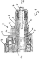
- FIG. 2 shows a section through the quick-change unit according to the invention, in FIG. 2 the lower part being cut in a rotational position rotated by 90 ° with respect to the upper part
- FIG. 3 one Section through the fixing washer, as used in Fig. 2.
- a drive head 1 is shown, the housing is formed in two parts.
- the front housing 2 is connected to the housing 3 carrying the rotary drive via screws 4.
- the front housing part 2 carries rinsing line connections, not shown, which are aligned with the channels 5 of a rinsing sleeve component 6.
- a bearing component 7 is also provided, which carries the radial bearing for the exchangeable drilling tool or the insertion tool 8.
- the insertion tool 8 has a stop shoulder 9 which cooperates with the stop shoulder 11 of a pressure ring 12 when the tool is pulled in the direction of the arrow 10.
- the pressure ring is stationary in the housing. When pulling and rotating insertion tool 8, the abutment surfaces 9 and 11 can rub, whereby the required torque increases significantly.
- the rotary drive is indicated schematically by the gear wheels 13, the insertion tool 8 being rotationally engaged with the bush 14 meshing with the gear wheel 13 and being axially displaceable for the purpose of a percussion drive.
- the screw 4 When changing the tool 8 in the embodiment of FIG. 1, the screw 4 must first be loosened. During further disassembly, the bearing component 7 and the flushing sleeve component 6 remain in the front housing part 2.
- the pressure ring is either inserted in the front housing part 2 or in the housing 3 and must be dismantled separately. The assembly is correspondingly complex.
- the rotary drive comprises a gear wheel 13.
- a guide bush 15 which is mounted relative to the front housing 2 via radial slide bearings 16 and relative to the insertion tool 8 via a further radial slide bearing 17.
- the guide bushing 15 has channels 18 and an annular space 19, via which flushing fluid can get into the corresponding connection channels 20 of the insertion tool 8.
- the connection for the fluid line opens on the outside of the front housing 2 and is schematically indicated at 21.
- the bearing bush 15 is connected to the rotary drive in a predetermined rotational position, secured by a securing bolt 22.
- the rotary drive is connected via dowel pins 23 to a fixing disk 24, this fixing disk, as can be seen in particular from FIG. 3, has recesses 25 and projections 26.
- the guide bushing can be adjusted with a corresponding rotational position of the guide bushing, whereupon the locking bolt 23 can be inserted through the bore 27 shown in FIG. 3 after being rotated through 90 ° and causes mutual locking.
- the bore 27 is provided in the wall of the sleeve 15.
- a corresponding recess is provided in the area of the projections 26 of the fixing disk 24, which ensures the rotationally locking connection of the bushing to the fixing disk 24 and thus the rotary drive 13.
- the bush 15 is thus in the locking position, as shown in Fig. 2 below, rotationally connected to the rotary drive and secured against axial displacement due to the projections 26 of the fixing washer 24.
- the rotational position is secured by the locking bolts 22.
- the securing bolt 22 To release a Relative rotation of the sleeve 15 and thus for rotation into a position in which the projections of the sleeve are aligned with the recesses 25 of the fixing washer, the securing bolt 22 must be displaced accordingly axially, for which purpose the head end 28 is rotated by 90 °.
- a transverse pin 29 comes into a transverse slot indicated in the secondary figure with 30, as a result of which the securing bolt 22 disengages from the fixing disk 24 while the spring 31 is relaxed.
- the guide bush 15 can subsequently be rotated through 90 ° and pulled off together with the insertion tool 8 and the front plate 32 rigidly connected to the bush.
- the fixing disk 24 is supported on the front housing 2 by the rotary drive via an axial bearing 33 and a radial bearing 35.
- the sleeve 15 can be pulled out together with the insertion tool 8 in the direction of the arrow 24.
- the assembly takes place in the opposite direction and is limited to turning the bushing after the insertion again into the locking position relative to the rotary drive and pushing the locking bolt 22 against the force of the spring 31 again and turning it into a position in which the Cross pin 29 prevents relaxation of the spring 31 and thus an axial displacement of the bolt.
- the tool 8 is shown in the position which is assumed when the tool is pulled out of the borehole.
- the end faces of the tool and the rotatably mounted bearing bush 15 abut one another. Since there is no relative rotation, excessive wear cannot occur in the area of the end faces.
Landscapes
- Life Sciences & Earth Sciences (AREA)
- Engineering & Computer Science (AREA)
- Geology (AREA)
- Mining & Mineral Resources (AREA)
- Physics & Mathematics (AREA)
- Environmental & Geological Engineering (AREA)
- Fluid Mechanics (AREA)
- General Life Sciences & Earth Sciences (AREA)
- Geochemistry & Mineralogy (AREA)
- Earth Drilling (AREA)
- Percussive Tools And Related Accessories (AREA)
Applications Claiming Priority (2)
| Application Number | Priority Date | Filing Date | Title |
|---|---|---|---|
| AT58595A AT406288B (de) | 1995-03-31 | 1995-03-31 | Antriebskopf für die aufnahme und führung eines einsteckwerkzeuges |
| AT585/95 | 1995-03-31 |
Publications (2)
| Publication Number | Publication Date |
|---|---|
| EP0735230A2 true EP0735230A2 (fr) | 1996-10-02 |
| EP0735230A3 EP0735230A3 (fr) | 1998-09-23 |
Family
ID=3494487
Family Applications (1)
| Application Number | Title | Priority Date | Filing Date |
|---|---|---|---|
| EP96890055A Withdrawn EP0735230A3 (fr) | 1995-03-31 | 1996-03-22 | Tête de propulsion pour la réception et le guidage d'un outil d'insertion |
Country Status (2)
| Country | Link |
|---|---|
| EP (1) | EP0735230A3 (fr) |
| AT (1) | AT406288B (fr) |
Cited By (2)
| Publication number | Priority date | Publication date | Assignee | Title |
|---|---|---|---|---|
| US6578644B2 (en) | 2000-12-12 | 2003-06-17 | Hilti Aktiengesellschaft | Percussion rotary hand-held power tool with a rotatable guide tube |
| EP2313602A4 (fr) * | 2008-06-03 | 2015-11-11 | Atlas Copco Rock Drills Ab | Dispositif et procédé comprenant une tête de rinçage pour une perforatrice, et perforatrice comprenant le dispositif |
Family Cites Families (5)
| Publication number | Priority date | Publication date | Assignee | Title |
|---|---|---|---|---|
| GB265043A (en) * | 1926-04-28 | 1927-02-03 | Percy Mynors Holman | Improvements in or relating to rock drills and like tools |
| US1664625A (en) * | 1927-03-04 | 1928-04-03 | Ingersoll Rand Co | Rotation mechanism for rock drills |
| US2337312A (en) * | 1943-04-27 | 1943-12-21 | Sullivan Machinery Co | Chuck mechanism |
| US3145787A (en) * | 1961-12-21 | 1964-08-25 | Jersey Prod Res Co | Rotary and input drilling apparatus |
| DE2459982C3 (de) * | 1974-12-18 | 1978-05-03 | Sandvik Ab, Sandviken (Schweden) | Kupplungsvorrichtung zur Verbindung einer Dreh-Schlag-Bohrmaschine mit einem Doppelgestänge |
-
1995
- 1995-03-31 AT AT58595A patent/AT406288B/de not_active IP Right Cessation
-
1996
- 1996-03-22 EP EP96890055A patent/EP0735230A3/fr not_active Withdrawn
Cited By (2)
| Publication number | Priority date | Publication date | Assignee | Title |
|---|---|---|---|---|
| US6578644B2 (en) | 2000-12-12 | 2003-06-17 | Hilti Aktiengesellschaft | Percussion rotary hand-held power tool with a rotatable guide tube |
| EP2313602A4 (fr) * | 2008-06-03 | 2015-11-11 | Atlas Copco Rock Drills Ab | Dispositif et procédé comprenant une tête de rinçage pour une perforatrice, et perforatrice comprenant le dispositif |
Also Published As
| Publication number | Publication date |
|---|---|
| EP0735230A3 (fr) | 1998-09-23 |
| AT406288B (de) | 2000-03-27 |
| ATA58595A (de) | 1999-08-15 |
Similar Documents
| Publication | Publication Date | Title |
|---|---|---|
| WO2020245000A1 (fr) | Clé de service pour porte-outils fixes et entraînés | |
| DE1477357A1 (de) | Vorrichtung zum Verbinden eines Werkzeuges mit der Spindel einer Werkzeugmaschine | |
| DE3725240C2 (fr) | ||
| EP0334807B1 (fr) | Dispositif de perçage à chambrage | |
| DE4105201C2 (fr) | ||
| DE3311289A1 (de) | Universalfraeskopf fuer eine werkzeugmaschine | |
| DE19641133C2 (de) | Wechselvorrichtung für Wellen-Nabe-Verbindungen | |
| EP0401156B1 (fr) | Dispositif d'alésage de contre-dépouille | |
| AT406288B (de) | Antriebskopf für die aufnahme und führung eines einsteckwerkzeuges | |
| DE2156153A1 (de) | Spindelanordnung fuer werkzeugmaschinen | |
| EP1860275A1 (fr) | Dispositif de couplage | |
| DE4236282C1 (de) | Schneckenkupplungseinrichtung an einer Kunststoff-Spritzgießmaschine | |
| DE3879226T2 (de) | Eine greifende und rotierende zangenanordnung. | |
| EP0545004A2 (fr) | Entraînement pour rotatives | |
| EP0882823B1 (fr) | Dispositif d'accouplement d'ensouple | |
| DE4432084C2 (de) | Verfahren und Werkzeug zum Aus- und Einbauen eines Walzringes | |
| EP1877610A1 (fr) | Metier a tisser dote d'une liaison amovible entre un moyen d'entrainement et l'ensouple d'un metier a tisser | |
| DE19837147C5 (de) | Spannfutter für Werkzeugmaschinen | |
| WO1999024200A1 (fr) | Raccord rapide pour outils de foreuse a pointes de diamants, en particulier pour outils de foreuse a carottage (raccord rapide de couronne de forage) | |
| DE102023200289B4 (de) | Vorrichtung, welche ein Rotationswerkzeug aufweist, und Verfahren zum Befestigen oder Lösen eines Schneideinsatzes bei einer solchen Vorrichtung | |
| CH695506A5 (de) | Rammgerät. | |
| CH665256A5 (de) | Bohrhammer mit einem drehmoment-einstellschluessel. | |
| DE1956210A1 (de) | Kupplungsvorrichtung zum Verbinden eines Paares von koaxialen Teilen | |
| DE19817144C1 (de) | Lösbare Verbindung für das mehrteilige Bohrgestänge eines als hydraulische Schlagdrehbohrvorrichtung ausgebildeten Bohrantriebs | |
| EP1808246B1 (fr) | Mandrin pour outils rotatifs |
Legal Events
| Date | Code | Title | Description |
|---|---|---|---|
| PUAI | Public reference made under article 153(3) epc to a published international application that has entered the european phase |
Free format text: ORIGINAL CODE: 0009012 |
|
| AK | Designated contracting states |
Kind code of ref document: A2 Designated state(s): AT BE CH DE DK ES FI FR GB GR IE IT LI LU NL PT SE |
|
| AX | Request for extension of the european patent |
Free format text: LT PAYMENT 960301;LV PAYMENT 960301;SI PAYMENT 960301 |
|
| RAX | Requested extension states of the european patent have changed |
Free format text: LT PAYMENT 960301;LV PAYMENT 960301;SI PAYMENT 960301 |
|
| PUAL | Search report despatched |
Free format text: ORIGINAL CODE: 0009013 |
|
| AK | Designated contracting states |
Kind code of ref document: A3 Designated state(s): AT BE CH DE DK ES FI FR GB GR IE IT LI LU NL PT SE |
|
| AX | Request for extension of the european patent |
Free format text: LT PAYMENT 960301;LV PAYMENT 960301;SI PAYMENT 960301 |
|
| 17P | Request for examination filed |
Effective date: 19981023 |
|
| 17Q | First examination report despatched |
Effective date: 19990722 |
|
| RAP1 | Party data changed (applicant data changed or rights of an application transferred) |
Owner name: BOEHLER PNEUMATIK INTERNATIONAL GMBH & CO KG |
|
| GRAG | Despatch of communication of intention to grant |
Free format text: ORIGINAL CODE: EPIDOS AGRA |
|
| GRAG | Despatch of communication of intention to grant |
Free format text: ORIGINAL CODE: EPIDOS AGRA |
|
| GRAH | Despatch of communication of intention to grant a patent |
Free format text: ORIGINAL CODE: EPIDOS IGRA |
|
| STAA | Information on the status of an ep patent application or granted ep patent |
Free format text: STATUS: THE APPLICATION IS DEEMED TO BE WITHDRAWN |
|
| 18D | Application deemed to be withdrawn |
Effective date: 20011206 |