EP0735377A2 - Prüfung der Induktion von Metalldetektorspulen - Google Patents
Prüfung der Induktion von Metalldetektorspulen Download PDFInfo
- Publication number
- EP0735377A2 EP0735377A2 EP96200826A EP96200826A EP0735377A2 EP 0735377 A2 EP0735377 A2 EP 0735377A2 EP 96200826 A EP96200826 A EP 96200826A EP 96200826 A EP96200826 A EP 96200826A EP 0735377 A2 EP0735377 A2 EP 0735377A2
- Authority
- EP
- European Patent Office
- Prior art keywords
- detection
- output signal
- magnitude
- signal
- coil
- Prior art date
- Legal status (The legal status is an assumption and is not a legal conclusion. Google has not performed a legal analysis and makes no representation as to the accuracy of the status listed.)
- Granted
Links
- 238000012360 testing method Methods 0.000 title claims abstract description 63
- 239000002184 metal Substances 0.000 title claims abstract description 54
- 238000001514 detection method Methods 0.000 claims abstract description 102
- 230000007246 mechanism Effects 0.000 claims description 8
- 238000000034 method Methods 0.000 claims description 4
- 230000015654 memory Effects 0.000 abstract description 5
- 230000004907 flux Effects 0.000 description 5
- 239000000463 material Substances 0.000 description 5
- 238000012546 transfer Methods 0.000 description 4
- 239000004459 forage Substances 0.000 description 3
- 238000003306 harvesting Methods 0.000 description 3
- 241001124569 Lycaenidae Species 0.000 description 2
- 230000002950 deficient Effects 0.000 description 2
- 230000001419 dependent effect Effects 0.000 description 2
- 238000013461 design Methods 0.000 description 2
- 230000006698 induction Effects 0.000 description 2
- 238000004382 potting Methods 0.000 description 2
- 230000004044 response Effects 0.000 description 2
- 230000035945 sensitivity Effects 0.000 description 2
- 230000002159 abnormal effect Effects 0.000 description 1
- 230000008859 change Effects 0.000 description 1
- 125000004122 cyclic group Chemical group 0.000 description 1
- 230000007547 defect Effects 0.000 description 1
- 238000010586 diagram Methods 0.000 description 1
- 239000000428 dust Substances 0.000 description 1
- 230000000694 effects Effects 0.000 description 1
- 230000001939 inductive effect Effects 0.000 description 1
- 238000012986 modification Methods 0.000 description 1
- 230000004048 modification Effects 0.000 description 1
- 230000002093 peripheral effect Effects 0.000 description 1
- 238000012545 processing Methods 0.000 description 1
- 230000003068 static effect Effects 0.000 description 1
- 238000006467 substitution reaction Methods 0.000 description 1
Images

Classifications
-
- G—PHYSICS
- G01—MEASURING; TESTING
- G01V—GEOPHYSICS; GRAVITATIONAL MEASUREMENTS; DETECTING MASSES OR OBJECTS; TAGS
- G01V13/00—Manufacturing, calibrating, cleaning, or repairing instruments or devices covered by groups G01V1/00 – G01V11/00
-
- G—PHYSICS
- G01—MEASURING; TESTING
- G01V—GEOPHYSICS; GRAVITATIONAL MEASUREMENTS; DETECTING MASSES OR OBJECTS; TAGS
- G01V3/00—Electric or magnetic prospecting or detecting; Measuring magnetic field characteristics of the earth, e.g. declination, deviation
- G01V3/08—Electric or magnetic prospecting or detecting; Measuring magnetic field characteristics of the earth, e.g. declination, deviation operating with magnetic or electric fields produced or modified by objects or geological structures or by detecting devices
- G01V3/10—Electric or magnetic prospecting or detecting; Measuring magnetic field characteristics of the earth, e.g. declination, deviation operating with magnetic or electric fields produced or modified by objects or geological structures or by detecting devices using induction coils
- G01V3/104—Electric or magnetic prospecting or detecting; Measuring magnetic field characteristics of the earth, e.g. declination, deviation operating with magnetic or electric fields produced or modified by objects or geological structures or by detecting devices using induction coils using several coupled or uncoupled coils
- G01V3/105—Electric or magnetic prospecting or detecting; Measuring magnetic field characteristics of the earth, e.g. declination, deviation operating with magnetic or electric fields produced or modified by objects or geological structures or by detecting devices using induction coils using several coupled or uncoupled coils forming directly coupled primary and secondary coils or loops
Definitions
- This invention relates to the testing of detection coils in a metal detector of an agricultural harvesting machine and more particularly to the testing of the inductance of the detection coils in a multi-channel magnetic metal detector.
- metal detectors in crop processing machines such as forage harvesters, the purpose of the metal detectors being to detect metal picked up from a field with the crop material.
- the metal detector detects the passage of a metal object through the crop feed path, the detector produces an output signal to stop the crop feed mechanism before the metal object can be fed into the crop cutter knives.
- the metal detector detection coils and associated detection circuits may be located within a housing to protect them from dust and moisture.
- the housing may in turn be located within a rotatable crop feed roll so as to position the detection coils as close as possible to the crop feed path.
- the coils may also be encased in a potting material. This makes it difficult to access the detection coils for test purposes.
- test coil for testing purposes, the test coil being disposed in proximity to the detection coils so that an emf (electromotive force) is induced in the detection coils upon application of a signal to the test coil.
- emf electroactive force
- Such additional coil may be removable as in the test apparatus of US-A-4,639,666.
- Such apparatus is not readily available to the operators of the harvesting machine during or in between harvesting operations and its use involves disconnecting portions of the metal detector circuitry in order to plug in the connector of the test apparatus, such that frequent testing is rather discouraged.
- Some metal detectors such as the one illustrated in US-A-4,433,528 have two channels. That is, the detectors have two detection coils, each connected to a respective one of two detection circuits which serve to amplify and filter the output signals from the detection coils. To insure a more uniform sensitivity of the metal detector across the width of the crop feed path, each detection coil is formed so as to comprise a series of generally triangular segments, the segments of one coil nesting between two segments of the other coil. Because of the close spacing, the detection coils are mutually inductively coupled. The present invention utilizes this mutual inductance in the testing of the inductance of the coils.
- a method for simultaneous testing the inductance of detection coils in a metal detector of an agricultural machine
- the sensed output signal may be used for comparison with a predetermined range of values, corresponding to normal coil conditions, and producing an error signal when it fall outside said range.
- an apparatus for testing the inductance of detection coils in a metal detector of an agricultural machine comprising:
- This testing apparatus may also comprise means for comparing the output signal from the second circuit with a range of values, corresponding to normal coil conditions and generate an error signal when it does not fall in said range.
- the applied test signal may be a square wave signal. It may be generated by a digital to analog converter which is loaded with a series of words representing the magnitude of the wave signal at successive points in time.
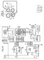
- the metal detector is located within a housing 70 that is in turn located within a rotatable lower front feed roll 72.
- Crop material 73 is picked up from a field by a pick-up mechanism (not shown) and fed between lower and upper front feed rolls 72, 71 and lower and upper rear feed rolls 76, 74 to a cutter mechanism comprising a rotating reel 78 having peripheral cutter knives 75 cooperating with a stationary cutter bar 77 to cut the crop material.
- a cutter mechanism comprising a rotating reel 78 having peripheral cutter knives 75 cooperating with a stationary cutter bar 77 to cut the crop material.
- metal objects fed between knives 75 and cutter bar 76 can severely damage the cutter mechanism.
- the metal detector prevents such damage by sensing metal objects and, upon sensing such an object, producing an output signal which is applied to a stop mechanism 98 to stop the feed rolls.
- the metal detector comprises first and second detector coils 10, 12, connected respectively to first and second channels or detection circuits 14, 16.
- coils 10, 12 are mutually inductively coupled and are disposed in magnetic detection fields generated by suitable means (not shown) so that metal objects passing through the magnetic detection fields perturb the flux of the fields thereby inducing an emf (electromotive force) in the coils.
- suitable means not shown
- the arrangement of coils 10, 12 and the means for generating the magnetic fields may, for example, be as shown in US-A-4,433,528.
- Each detection circuit includes an RFI filter section 18, a balanced resistor network 20 feeding first and second inputs 21, 23 of a differential amplifier 22, and a low pass audio filter 24.
- the ends of coil 12 are connected to inputs of the RFI filter section 18, which serves to filter out any radio frequency interference picked up by coil 12.
- the output leads 26, 28 of filter section 18 are connected to the balanced resistor network 20 which comprises four resistors R 1 , R 2 , R 3 and R 4 .
- Resistors R 1 and R 2 have equal resistances (about 1 K).
- a bias voltage V2 (+2.5 V) is connected to a junction 30 between first ends of R 1 and R 2 .
- the second ends of R 1 and R 2 are connected to leads 26, 28 at junctions 32 and 34, respectively.
- Resistors R 3 and R 4 have equal resistances (about 250 K).
- One end of resistor R 3 is connected to the first input 21 of differential amplifier 22 and the other end is connected to junction 32.
- One end of resistor R 4 is connected to the second input 23 of differential amplifier 22 and the other end is connected to junction 34.
- the detection coil 12 is located in a static magnetic detection field so that in the absence of movement of a metal object through the detection field, there is no potential difference between the ends of coil 12 and V2 determines the voltages at the inputs of differential amplifier 22 and thus the steady state output of the amplifier.
- Moving parts of the agricultural machine distort the detection field and the field is further distorted each time a tramp metal object passes through the field. As the detection field is distorted, an emf is induced in coil 12.
- the induced emf first adds to V2 at one of junctions 32, 34 and opposes V2 at the other junction as a metal object enters the detection field and then reverses polarity as the metal object leaves the detection field. This results in unequal voltages being applied to the inputs of the differential amplifier 22 and it produces an output signal that varies about the steady state reference according to the difference in potential at inputs 21, 23.
- the output signal from differential amplifier 22 is applied to the filter 24.
- Filter 24 filters out the high frequency "noise” caused by cyclic movement of parts of the agricultural machine in the detection field.
- the filtered signal CH1 at the output of filter 24 is applied via a lead 36 to one input of a multi-channel analog to digital converter (ADC) 40 (Fig. 1B).
- ADC analog to digital converter
- ADC 40 The purpose of ADC 40 is to convert the magnitudes of the analog signals CH0 and CH1 to digital values representing the magnitudes of the signals.
- the ADC is controlled by a conventional microcomputer 42 having a CPU and RAM, ROM and E 2 PROM memories.
- a serial bus link 41 interconnects the microcomputer 42 and ADC 40.
- the microcomputer executes a program during which it sends signals to the ADC 40 to enable the ADC, select one of the input channels, and transfer to the microcomputer a digital signal DATA, representing the magnitude of the output signal of the selected channel at the time the ADC is enabled.
- the ADC 40 is controlled to sample and digitize each of the signals CH0 and CH1 every 2.5 ms.
- a positive and a negative threshold or reference value is stored in the E 2 PROM memory of the microcomputer for each of the metal detector channels.
- each digital value transferred from the ADC is compared with the positive and negative threshold values for that channel.
- the threshold values define the upper and lower limits within which the magnitude of the output signal from a respective channel will fall as long as the coil connected to the channel does not detect the passage of a tramp metal object. If a comparison shows that a value produced by ADC 40 is greater than the positive threshold value or less than (i.e.
- the microcomputer 42 produces an output signal that is applied via serial data link 43 which may be a Controller Area Network (CAN), and a further microcomputer 45 to the stop mechanism 98 to stop the crop feed rolls.
- serial data link 43 which may be a Controller Area Network (CAN)
- CAN Controller Area Network
- the inductance of detection coils 10, 12 is tested by injecting a test signal of known magnitude into the detection coil connected to one detection circuit and determining the magnitude of the resulting output signal from the other detection circuit.
- the apparatus for injecting the test signal comprises an digital to analog converter (DAC) 44, a buffer 54, FET switches 50 and a latch register 48, in addition to microcomputer 42.
- DAC digital to analog converter
- DAC 44 is connected to microcomputer 42 via the serial data link 41.
- the microcomputer enables DAC 44 every 2.5 ms and transfers a digital value to a holding register in the DAC.
- the DAC converts the digital value to an equivalent analog voltage which is applied over a lead 52 to an attenuator 46 and a buffer 54.
- the buffer 54 is used for inductance testing of coils 10 and 12. Inductance testing requires a larger test signal than resistance testing and since DAC 44 may be used to generate the test signal for both tests, attenuator 46 serves to reduce the magnitude of the test signal during resistance testing.
- the output of attenuator 46 is connected to inputs 1B and 4B of two FET switches 50 and the output of buffer 54 is connected to inputs 2B and 3B of two further FET switches 50. Only one of the switches is turned on at a time, the active switch being determined by which of the addressing or selection signals SW1-SW4 is active.
- the signals SW3 and SW4 enable third and fourth switches, respectively so that the output of buffer 54 is passed through the third switch to output 3A or the output of attenuator 46 is passed through the fourth switch to the output 4A.
- Outputs 3A and 4A are connected together and are further connected through a resistor 58 to a point in detector channel 0 corresponding to the junction 32 in channel 1.
- the selection signals are applied to switches 50 from the register 48.
- Register 48 is an 8-bit serial input, parallel output register with latches. The register receives data from microcomputer 42 via the serial data link 41.
- microprocessor 42 sends a code word to latch register 48 to select which detection coil 10, 12 is to receive the test signal and which test is to be performed.
- the test performed and the coil to which the test signal is applied are determined by a 1-bit in one of four bit positions of the code word as indicated in the following table: TABLE I Code Word Register Output Test Performed 1000 0000 SW1 Resistance of coil 12 0100 0000 SW2 Inductance, signal applied to coil 12 0010 0000 SW3 Inductance, signal applied to coil 10 0001 0000 SW4 Resistance of coil 10
- the microcomputer 42 enables DAC 44 every 2.5 ms and transfers to a holding register in the DAC a digital value representing a point on a square wave.
- the digital values applied to DAC 44 are such that the DAC produces a square wave output signal having a low frequency.
- the frequency is such that an output signal, produced by the amplifier 22 in one of the detection circuits 14, 16 in response to the square wave as subsequently described, will pass through the low pass filter 24 in the detection circuit.
- the square wave signal is applied in parallel through buffer 54 and attenuator 46 to inputs of switches 50.
- the attenuator 46 is used only during resistance testing of detection coils 10, 12 as explained above and is not used during inductance testing of the coils.
- the code word initially loaded into latch register 48 will be 0010 0000 and the register produces the signal SW3 test if the induction test signal is to be injected into detection coil 10.
- the register is loaded with the value 0100 0000 so that it produces the signal SW2.
- the square wave output signal from DAC 44 passes through buffer 54, one of switches 50 and a resistor 36 to one end of detection coil 12.
- the resulting current flow through detection coil 12 produces a periodically varying magnetic field with flux lines linking detection coil 10. As the flux linking coil 10 varies, an emf is induced in coil 10.
- the number of flux lines produced by detection coil 12 is proportional to the inductance of coil 12 and the emf induced in coil 10 is proportional to the inductance of coil 10; hence the emf induced in coil 10 has a magnitude that is dependent on the inductances of both coils and may be measured to detect variations in the inductances of the coils.
- the emf induced in coil 10 is directly proportional to the time rate of change of the flux linkages. It is for this reason that a square wave is injected as the test signal.
- the induced emf in coil 10 provides a potential difference between the ends of the coil which is amplified and filtered by detection circuit 14 and applied to ADC 40.
- Microcomputer 42 enables ADC 40 every 2.5 ms and transfers to the microcomputer a digital value representing the magnitude of the output signal CH0 from detection circuit 14.
- the microcomputer includes a flash ROM (E 2 PROM) memory.
- This memory stores first and second threshold values MIN and MAX, respectively.
- MIN represents the minimum acceptable magnitude of an output signal from the metal detector when the square wave signal is applied to coil 12
- MAX represents the maximum acceptable magnitude of an output signal from the metal detector when the square wave signal is applied to coil 12. Since the magnitude of the square wave signal applied to coil 12 is known, one may calculate from the circuit design of the detection channels what the maximum positive magnitude (X) of the output signal from the metal detector should be.
- the threshold values MAX and MIN are chosen to be greater than, and less than X, respectively.
- the differences between MAX and X and MIN and X are dependent on tolerance, that is, on how much variation in a detector output signal is acceptable without unduly affecting the performance of the detector.
- the tolerance value is added to X to determine MAX and subtracted from X to determine MIN. Having made this determination, the threshold values MAX and MIN are loaded into the E 2 PROM at the factory or when a new metal detector is installed and thus define a predetermined range of acceptable magnitudes of the detector output signal in response to the square wave signal.
- the digital values produced by ADC 40 during the time the square wave is applied to coil 12, are applied to a positive peak detector 66 implemented by programming in the microcomputer 42.
- the peak detector determines the peak or largest of the digital values produced by the ADC 40. This peak value is then compared by a comparator 68 with MAX and MIN. If the peak value is greater than MAX or less than MIN, the microcomputer sends an error message via serial data link 43 and microcomputer 45 to a display 60 to provide an operator with an indication that the inductance test of the metal detector coils has found an abnormal condition.
- the coil inductance test described above does not measure the inductance of a detection coil nor does it provide an indication of which coil 10 or 12 is defective. It merely provides an indication that one of the coils is defective. This presents no problem since the coils are normally embedded in potting material and replaced as a unit in the event of a defect or failure.
- the test may also be performed by injecting the square wave into coil 10 while ADC 40 samples the output signal from detection channel or circuit 16.
- latch register 48 is loaded with the value 0010 000 so that the signal SW3 is produced.
- SW3 enables a switch 50 so that the square wave from buffer 54 is applied through resistor 58 to coil 10.
- Microcomputer 42 controls ADC 40 so that the output signal from detection circuit 14 is sampled and transferred to the computer for comparison with MAX and MIN.
- the test result is the same, regardless of whether the test signal is injected into detection coil 10 or detection coil 12.
Landscapes
- Life Sciences & Earth Sciences (AREA)
- Engineering & Computer Science (AREA)
- Physics & Mathematics (AREA)
- Geophysics (AREA)
- General Life Sciences & Earth Sciences (AREA)
- General Physics & Mathematics (AREA)
- Remote Sensing (AREA)
- Manufacturing & Machinery (AREA)
- Electromagnetism (AREA)
- Environmental & Geological Engineering (AREA)
- Geology (AREA)
- Geophysics And Detection Of Objects (AREA)
- Investigating Or Analyzing Materials By The Use Of Magnetic Means (AREA)
Applications Claiming Priority (4)
| Application Number | Priority Date | Filing Date | Title |
|---|---|---|---|
| US08/414,788 US5627475A (en) | 1995-03-31 | 1995-03-31 | Metal detector coil resistance testing |
| US414788 | 1995-03-31 | ||
| US08/414,330 US5644236A (en) | 1995-03-31 | 1995-03-31 | Method and apparatus for simultaneously testing the inductance of detection coils in a multiple channel metal detector |
| US414330 | 1995-03-31 |
Publications (3)
| Publication Number | Publication Date |
|---|---|
| EP0735377A2 true EP0735377A2 (de) | 1996-10-02 |
| EP0735377A3 EP0735377A3 (de) | 1997-09-03 |
| EP0735377B1 EP0735377B1 (de) | 2004-03-17 |
Family
ID=27022506
Family Applications (1)
| Application Number | Title | Priority Date | Filing Date |
|---|---|---|---|
| EP19960200826 Expired - Lifetime EP0735377B1 (de) | 1995-03-31 | 1996-03-27 | Prüfung der Induktion von Metalldetektorspulen |
Country Status (2)
| Country | Link |
|---|---|
| EP (1) | EP0735377B1 (de) |
| DE (1) | DE69631850T2 (de) |
Cited By (4)
| Publication number | Priority date | Publication date | Assignee | Title |
|---|---|---|---|---|
| GB2457954A (en) * | 2008-02-29 | 2009-09-02 | Radiodetection Ltd | Electromagnetic detector for detecting a current carrying conductor |
| EP3002614A1 (de) * | 2014-10-03 | 2016-04-06 | Cable Detection Limited | Erdeinbaudetektion |
| CN109283598A (zh) * | 2018-08-24 | 2019-01-29 | 西安陆海地球物理科技有限公司 | 检波器测试仪的震动激励系统及方法 |
| US10209385B2 (en) | 2014-10-03 | 2019-02-19 | Cable Detection Limited | Buried service detection |
Families Citing this family (1)
| Publication number | Priority date | Publication date | Assignee | Title |
|---|---|---|---|---|
| EP4134712B1 (de) * | 2021-08-11 | 2024-05-22 | Sesotec GmbH | Verfahren zur überprüfung der funktion eines metalldetektors |
Family Cites Families (2)
| Publication number | Priority date | Publication date | Assignee | Title |
|---|---|---|---|---|
| US4084135A (en) * | 1975-08-25 | 1978-04-11 | The Goodyear Tire & Rubber Company | System and method for checking the sensitivity and performance of an electromagnetic field variation detector |
| US4230987A (en) * | 1979-02-26 | 1980-10-28 | Sensor Corporation | Digital eddy current apparatus for generating metallurgical signatures and monitoring metallurgical contents of an electrically conductive material |
-
1996
- 1996-03-27 EP EP19960200826 patent/EP0735377B1/de not_active Expired - Lifetime
- 1996-03-27 DE DE69631850T patent/DE69631850T2/de not_active Expired - Lifetime
Cited By (11)
| Publication number | Priority date | Publication date | Assignee | Title |
|---|---|---|---|---|
| GB2457954A (en) * | 2008-02-29 | 2009-09-02 | Radiodetection Ltd | Electromagnetic detector for detecting a current carrying conductor |
| US8115489B2 (en) | 2008-02-29 | 2012-02-14 | Radiodetection Limited | Detector for detecting a current carrying conductor and a method of validating operation of the detector |
| GB2457954B (en) * | 2008-02-29 | 2012-04-04 | Radiodetection Ltd | A detector for detecting a current carrying conductor and a method of validating operations of the detector |
| CN101526626B (zh) * | 2008-02-29 | 2012-07-25 | 雷迪有限公司 | 一种探测载流导体的探测装置及对其探测操作的验证方法 |
| EP2096466B1 (de) * | 2008-02-29 | 2019-12-11 | Radiodetection Limited | Detektor zur Erkennung eines stromführenden Leiters und Verfahren zur Überprüfung des Detektorbetriebs |
| EP3002614A1 (de) * | 2014-10-03 | 2016-04-06 | Cable Detection Limited | Erdeinbaudetektion |
| CN105487123A (zh) * | 2014-10-03 | 2016-04-13 | 电缆检测有限公司 | 埋地公共设施检测 |
| US10151850B2 (en) | 2014-10-03 | 2018-12-11 | Cable Detection Limited | Buried service detection |
| US10209385B2 (en) | 2014-10-03 | 2019-02-19 | Cable Detection Limited | Buried service detection |
| CN109283598A (zh) * | 2018-08-24 | 2019-01-29 | 西安陆海地球物理科技有限公司 | 检波器测试仪的震动激励系统及方法 |
| CN109283598B (zh) * | 2018-08-24 | 2021-08-03 | 西安陆海地球物理科技有限公司 | 检波器测试仪的震动激励系统及方法 |
Also Published As
| Publication number | Publication date |
|---|---|
| EP0735377A3 (de) | 1997-09-03 |
| EP0735377B1 (de) | 2004-03-17 |
| DE69631850T2 (de) | 2004-08-12 |
| DE69631850D1 (de) | 2004-04-22 |
Similar Documents
| Publication | Publication Date | Title |
|---|---|---|
| EP0735376B1 (de) | Prüfung des Widerstandes einer Metalldetektorspule | |
| US5677634A (en) | Apparatus for stress testing capacitive components | |
| EP0358483B1 (de) | Automatischer Felderdungsdetektor und Lokalisator | |
| US5921939A (en) | Device for monitoring measurement electrodes to detect the presence of faults in electrode, leads and in the connection of the electrodes to a patient | |
| US6025711A (en) | Sensor circuit with diagnostic capability | |
| DE10131229B4 (de) | Eine physikalische Größe erfassender Sensor | |
| US4417590A (en) | Electroencephalograph | |
| US4746869A (en) | Circuit for testing inductive coils | |
| US4030012A (en) | Amplifier malfunction detector | |
| EP0735377B1 (de) | Prüfung der Induktion von Metalldetektorspulen | |
| US5644236A (en) | Method and apparatus for simultaneously testing the inductance of detection coils in a multiple channel metal detector | |
| US4409987A (en) | Electroencephalograph | |
| DE69203007T2 (de) | Vorrichtung zur Fehleridentifizierung in Fahrzeuginsassen-Schutzsystemen. | |
| US4202354A (en) | Electroencephalograph | |
| US4382227A (en) | Multipurpose test equipment input circuitry | |
| CA1040267A (en) | Automatic zeroing electrometer | |
| US6598182B1 (en) | Electromigration and extrusion monitor and control system | |
| US4562429A (en) | Static event detector and tape probe | |
| US4204546A (en) | Electroencephalograph | |
| EP0366453A2 (de) | Variabler Strom-Spannungs-Verstärker mit einem verstärkungsunabhängigen Prüfungsmodus | |
| US4236511A (en) | Electroencephalograph | |
| JPH09152303A (ja) | 位置検出装置 | |
| EP0826984B1 (de) | Wandlerschaltung mit Frequenzveränderungsfähigkeit | |
| CN218272670U (zh) | 一种霍尔电流传感器故障检测装置 | |
| JP2768793B2 (ja) | 原子炉の出力領域中性子モニタ |
Legal Events
| Date | Code | Title | Description |
|---|---|---|---|
| PUAI | Public reference made under article 153(3) epc to a published international application that has entered the european phase |
Free format text: ORIGINAL CODE: 0009012 |
|
| AK | Designated contracting states |
Kind code of ref document: A2 Designated state(s): DE FR GB |
|
| PUAL | Search report despatched |
Free format text: ORIGINAL CODE: 0009013 |
|
| AK | Designated contracting states |
Kind code of ref document: A3 Designated state(s): DE FR GB |
|
| 17P | Request for examination filed |
Effective date: 19980209 |
|
| RAP1 | Party data changed (applicant data changed or rights of an application transferred) |
Owner name: CNH BELGIUM N.V. |
|
| GRAP | Despatch of communication of intention to grant a patent |
Free format text: ORIGINAL CODE: EPIDOSNIGR1 |
|
| GRAS | Grant fee paid |
Free format text: ORIGINAL CODE: EPIDOSNIGR3 |
|
| GRAA | (expected) grant |
Free format text: ORIGINAL CODE: 0009210 |
|
| AK | Designated contracting states |
Kind code of ref document: B1 Designated state(s): DE FR GB |
|
| REG | Reference to a national code |
Ref country code: GB Ref legal event code: FG4D |
|
| REF | Corresponds to: |
Ref document number: 69631850 Country of ref document: DE Date of ref document: 20040422 Kind code of ref document: P |
|
| ET | Fr: translation filed | ||
| PLBE | No opposition filed within time limit |
Free format text: ORIGINAL CODE: 0009261 |
|
| STAA | Information on the status of an ep patent application or granted ep patent |
Free format text: STATUS: NO OPPOSITION FILED WITHIN TIME LIMIT |
|
| 26N | No opposition filed |
Effective date: 20041220 |
|
| REG | Reference to a national code |
Ref country code: DE Ref legal event code: R082 Ref document number: 69631850 Country of ref document: DE Representative=s name: PATENTANWAELTE WALLACH, KOCH & PARTNER, DE |
|
| PGFP | Annual fee paid to national office [announced via postgrant information from national office to epo] |
Ref country code: DE Payment date: 20140118 Year of fee payment: 19 |
|
| PGFP | Annual fee paid to national office [announced via postgrant information from national office to epo] |
Ref country code: FR Payment date: 20140115 Year of fee payment: 19 |
|
| REG | Reference to a national code |
Ref country code: DE Ref legal event code: R082 Ref document number: 69631850 Country of ref document: DE Representative=s name: PATENTANWAELTE WALLACH, KOCH, DR. HAIBACH, FEL, DE Effective date: 20140428 Ref country code: DE Ref legal event code: R082 Ref document number: 69631850 Country of ref document: DE Representative=s name: PATENTANWAELTE WALLACH, KOCH & PARTNER, DE Effective date: 20140428 Ref country code: DE Ref legal event code: R081 Ref document number: 69631850 Country of ref document: DE Owner name: CNH INDUSTRIAL BELGIUM NV, BE Free format text: FORMER OWNER: CNH BELGIUM NV, ZEDELGEM, BE Effective date: 20140428 |
|
| PGFP | Annual fee paid to national office [announced via postgrant information from national office to epo] |
Ref country code: GB Payment date: 20140120 Year of fee payment: 19 |
|
| REG | Reference to a national code |
Ref country code: FR Ref legal event code: CD Owner name: CNH INDUSTRIAL BELGIUM NV Effective date: 20140725 |
|
| REG | Reference to a national code |
Ref country code: DE Ref legal event code: R119 Ref document number: 69631850 Country of ref document: DE |
|
| GBPC | Gb: european patent ceased through non-payment of renewal fee |
Effective date: 20150327 |
|
| REG | Reference to a national code |
Ref country code: FR Ref legal event code: ST Effective date: 20151130 |
|
| PG25 | Lapsed in a contracting state [announced via postgrant information from national office to epo] |
Ref country code: GB Free format text: LAPSE BECAUSE OF NON-PAYMENT OF DUE FEES Effective date: 20150327 Ref country code: DE Free format text: LAPSE BECAUSE OF NON-PAYMENT OF DUE FEES Effective date: 20151001 |
|
| PG25 | Lapsed in a contracting state [announced via postgrant information from national office to epo] |
Ref country code: FR Free format text: LAPSE BECAUSE OF NON-PAYMENT OF DUE FEES Effective date: 20150331 |