EP0735448A2 - Machine vibrante - Google Patents
Machine vibrante Download PDFInfo
- Publication number
- EP0735448A2 EP0735448A2 EP96302168A EP96302168A EP0735448A2 EP 0735448 A2 EP0735448 A2 EP 0735448A2 EP 96302168 A EP96302168 A EP 96302168A EP 96302168 A EP96302168 A EP 96302168A EP 0735448 A2 EP0735448 A2 EP 0735448A2
- Authority
- EP
- European Patent Office
- Prior art keywords
- vibratory
- output
- detecting means
- self
- machine
- Prior art date
- Legal status (The legal status is an assumption and is not a legal conclusion. Google has not performed a legal analysis and makes no representation as to the accuracy of the status listed.)
- Granted
Links
Images













Classifications
-
- G—PHYSICS
- G05—CONTROLLING; REGULATING
- G05D—SYSTEMS FOR CONTROLLING OR REGULATING NON-ELECTRIC VARIABLES
- G05D19/00—Control of mechanical oscillations, e.g. of amplitude, of frequency, of phase
- G05D19/02—Control of mechanical oscillations, e.g. of amplitude, of frequency, of phase characterised by the use of electric means
Definitions
- This invention relates to vibratory apparatus which may be used, for example, for handling or transporting component parts such as bolts, nuts, electronic components, such as transistors, or the like.
- a closed loop consists of a vibratory machine 1, a vibration detector 2, a self-excited oscillation controller 3, a power amplifier 4, and a vibratory exciter 5.
- the phase lag of the transfer function is equal to 180 degrees at a certain frequency under the open loop condition, and the gain of the opened transfer function is larger than one (stability limit)
- a self-excited oscillation can be effected at the above certain frequency in the closed loop.
- the gain is required to be sufficiently high so as to improve the rise-up time of the self-excited oscillation.
- the gain may be equal to 100.
- the gain includes not only the gain of the vibration detector, the gain of the controller and the gain of the power amplifier, but also the input-output conversion gain of the vibratory exciter.
- the vibratory exciter 5 when it is an electro-magnet, it has the non-linear or square characteristic which is the relationship between the current flowing through the coil and the attractive force as shown in Fig.2. Accordingly, the input-output conversion gain or the differential coefficient is equal to zero or nearly equal to zero nearly at the current of zero or within the range shown by a reference mark A in Fig.2. A high gain cannot be obtained in an opened loop. Thus, a self-excited oscillation cannot be generated.
- a self-excited resonance-type vibratory apparatus has the advantage that it automatically follows up a resonance point.
- any control is required for maintaining an amplitude of a vibratory machine at a definite value.
- the output of the power amplifier is rectangular, and therefore, it includes much high frequency components.
- FIG.3 A self-excited vibratory apparatus Q as shown in Fig.3 was disclosed in the Japanese Patent Application No.154599/1986, in consideration of the above-described defects of the Prior Art.
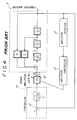
- Fig.4 shows a block diagram of transfer functions of an important part of the self-excited vibratory apparatus Q as shown in Fig.3.
- a vibratory machine is generally designated by a reference numeral 1', and it is represented by a shown characteristic equation.
- a vibration detector 2' is arranged adjacent to the vibratory machine 1'.
- the vibration detector 2' is an eddy current type sensor, and it is arranged adjacent to a leaf spring which combines a bowl (movable part) with a base.
- the output of the vibrator sensor 2' is supplied to an amplitude controller 3', and an output of the amplitude controller 3' is supplied to a power amplifier 4'.
- an output x of the vibratory machine 1' is supplied to a self-excited oscillation controller 7' which includes an adder 6' and a first order lag element 5'.
- the output x of the vibratory machine 1' is negatively fed-back to the adder 6'. Since the vibratory machine 1' is self-excited, another input to the adder 6' is zero.
- the output of the adder 6' is supplied to the first order lag element 5', and further an output of the first order lag element 5' is supplied to the power amplifier 4'.
- a mass m vibrates at an acceleration, dx 2 /dt 2 .
- the vibratory velocity of the mass m is equal to dx/dt, when the lag element is equal to 1/s, where s represents a Laplace transform.
- a damping force (cx dx/dt) is applied to the mass m , where c represents a viscous coefficient.
- the "dx/dt” is transferred to a displacement x by the lag element 1/s.
- a restoring force kx is further applied to the mass m , where k represents a spring constant of a restoring force of a spring.
- the vibratory machine 1' can be schematically represented by such a closed loop.
- the displacement x lags by 90 degrees behind the force at the resonant frequency. Since the displacement x is made to lag by 90 degrees, by the first order lag element 5' in the self-excited oscillation controller 7'.
- the phase difference is equal to 180 degree, in an opened loop.
- a self-excited oscillation becomes possible.
- a gain K 0 of the power amplifier 4' is over a stability limit
- the system shown in Fig.4 can self-excitedly oscillate.
- the difference between the present amplitude and a predetermined amplitude is detected in an amplitude controller 3'.
- the gain K 0 of the power amplifier 4' is controlled with the output representing the difference.
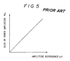
- the gain K 0 of the power amplifier 4' When the difference between the present amplitude and the predetermined amplitude is larger, the gain K 0 of the power amplifier 4' is higher. When the vibratory displacement of the vibratory machine 1' reaches the predetermined amplitude, the gain K 0 of the power amplifier 4' is brought to the stability limit. As shown in Fig.5, the relationship between the difference ⁇ r and the gain K 0 of the power amplifier 4' is linear. When the rise-up characteristic of the self-excited oscillation is made rapid, the gain K of the power amplifier 4' should be required to be sufficiently large, since the difference ⁇ r is large at the control start. However, the high frequency components or ripples of the output of the amplitude detector 2' is much amplified by the power amplifier 4'. Thus, the output of the power amplifier 4' varies very much. There is the disadvantage that the vibratory machine cannot be stably self-excitedly oscillated.
- Fig.6 shows a vibratory apparatus of the self-excited oscillation type of the Prior Art. It is generally denoted by a reference numeral 1".
- a vibratory machine 2 is, for example, a vibratory parts-feeder.
- a vibration detector 3" of the eddy current type is arranged adjacent to a leaf spring in the vibratory machine 2".
- An output of the vibration detector 3" is supplied to a self-excited oscillation controller 4".
- An out-put of the self-excited oscillation controller 4" is amplified by a power amplifier 5", and the amplified output is supplied to a vibratory exciter 6" which is, for example, the electro-magnetic exciter of the vibratory machine 2".
- the vibratory machine 2" is self-excitedly oscillated by the self-oscillation controller 4".
- a stop signal is supplied at time to as shown in Fig.7.
- an electric wire a between the self-excited oscillation controller 4" and the power amplifier 5" or another electric line b between the power amplifier 5" and the vibration exciter 6" is cut off.
- the amplitude of a movable part or a bowl of the vibratory machine 2" is exponentially decreased with time from time to .
- the bowl is vibrated at a predetermined amplitude till time to. It requires a considerable time that the amplitude of the bowl is reduced to 0.
- a spiral track is formed inside the bowl in the vibratory machine 2".
- Parts are oriented and posture-rectified along the spiral track in the bowl. It requires a considerable time that the amplitude of the bowl is reduced to zero after time to when the stop signal is generated. Accordingly,the parts supply is not stopped at the same time as the time to. For some time after time to , the parts continue to be supplied to the next stage. That is often a great disadvantage.
- the time that the amplitude of the bowl in the vibratory machine 2" is reduced to zero after the stop signal depends on the dumping characteristic of the vibratory machine 2". It is proportional to the velocity of the movable part. It is a resistive force. A force for vibrating the vibratory machine 2" at the resonant frequency increases with a dumping coefficients and it causes much loss of energy.
- Fig.8 shows another vibratory apparatus of the forced-vibration type. It is generally denoted by a reference numeral 1A.
- a current from the commercial supply 7 is supplied to an electro-magnetic coil 10 of an electro-magnet 9 in the vibratory parts-feeder 2A which is one example of the vibratory machine.
- the vibratory machine 2A is shown in details, in Fig.8.
- the frequency of the commercial supply 7 is equal to 50 Hz. It is supplied through a controller 8 to the vibratory machine 2A.
- the bowl 11 is oscillated at a predetermined amplitude.
- a switch is arranged at an electric line c between the commercial supply 7 and the controller 8, or an electric line d between the controller 8 and the electro-magnetic coil 10.
- the switch is turned off to stop the drive of the parts feeder 2.
- the bowl 11 is stopped.
- the vibratory parts-feeder 2 of the self-excited oscillation type it is transiently vibrated. Accordingly, it requires a considerable time that the amplitude of the bowl is reduced to 0.
- a vibratory apparatus comprising:
- a vibratory apparatus comprising:
- a vibratory apparatus comprising:
- a vibratory apparatus comprising:
- a vibratory apparatus comprising:
- a vibratory apparatus comprising:
- a vibratory apparatus comprising:
- a vibratory apparatus comprising:
- a vibratory apparatus comprising:
- a vibratory apparatus comprising:
- a vibratory apparatus comprising:
- a vibratory apparatus comprising: an exciting mechanism for imparting to said vibratory apparatus an electric power from an electric power source, the improvement in which vibratory speed detecting means is arranged adjacent to said movable part or attached to said movable part and said exciting mechanism is cut off from said electric power source when said vibratory apparatus is stopped, and the output of said vibratory speed detecting means is supplied directly to said exciting mechanism or amplified to said vibratory mechanism as a negative feed-back signal.
- Fig.1 is a block diagram of a vibratory apparatus of one Prior Art.
- Fig.2 is a chart for explaining operation of the Prior Art.
- Fig.3 is a block diagram of a vibratory apparatus of another Prior Art.
- Fig.4 is a block diagram of an important part of the other Prior Art.
- Fig.5 is a chart for explaining operation of the other Prior Art.
- Fig.6 is a block diagram of a further Prior Art.
- Fig.7 is a time chart for explaining the further Prior Art.
- Fig.8 is a side view of a vibratory apparatus of a further Prior Art.
- Fig.9 is a block diagram of a vibratory apparatus according to a first embodiment of this invention.
- Fig.10 is an enlarged view of a vibratory exciter in Fig.9.
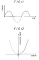
- Fig.ll is a chart for showing operation of the first embodiment.
- Fig.12 is another chart for explaining operation of the first embodiment.
- Fig.13 is a side view of a vibratory exciter according to a second embodiment of this invention.
- Fig.14 is a block diagram of an important part of a vibratory apparatus according to a third embodiment of this invention.
- Fig.15 is a chart for explaining the second embodiment of this invention.
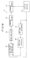
- Fig.16 is a block diagram of a vibratory apparatus according to a fourth embodiment of this invention.
- Fig.17 is a chart for explaining operation of the fourth embodiment.
- Fig.18 is a chart for explaining the comparison between this invention and the Prior Art
- Fig.19 is a chart for explaining the operation of the fourth embodiment of this invention.
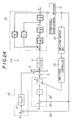
- Fig.20 is a block diagram of vibratory apparatus according to a fifth embodiment of this invention.
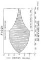
- Fig.21 is a chart for explaining the comparison between the Prior Art and this invention.
- Fig.22 is a chart for explaining the operation of the fifth embodiment of this invention.
- Fig.23 is a block diagram of a vibratory apparatus according to a sixth embodiment of this invention.
- Fig.24 is a block diagram of a vibratory apparatus according to a seventh embodiment of this invention.
- Fig.25 is a block diagram of an eighth embodiment of this invention.
- Fig.26 is a chart for explaining the operation of the eighth embodiment of this invention.
- Fig.27 is a chart for explaining a further operation of the eighth embodiment.
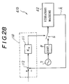
- Fig.28 is a block diagram of an important part of a ninth embodiment of this invention.
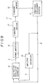
- Fig.9 shows a self-excited vibratory apparatus of the electro-magnet exciter type, according to a first embodiment of this invention. It is generally designated by a reference numeral 11.
- a vibratory machine 12 is a vibratory parts-feeder in this embodiment, the details of which is shown in Fig.10.
- a vibration displacement detector 13 is arranged adjacent to the vibratory parts-feeder 12. An output of the vibration displacement detector 13 is supplied to an amplitude (displacement) controller 14 which has the well-known construction. A predetermined amplitude is set in the amplitude controller 14. The output of the vibration displacement detector 13 is compared with the predetermined amplitude in the amplitude controller 14. An output of the amplitude controller 14 is supplied to an electric line b, which corresponds to the difference between the predetermined amplitude and the output of the vibration displacement detector 13.
- a self-excited oscillation controller 15 includes an alternative current amplifier 21 and a saturation limiter 22, as shown in Fig.14. An output of the controller 15 is supplied to an electric line c, and amplified by a power amplifier 16. An amplified output of the power amplifier 16 is supplied to a vibratory exciter 17.
- the vibratory exciter 17 is of the electro-magnet exciter type. It consists of an E-shaped stationary electro-magnet 18, an electro-magnetic coil 19 wound on the stationary electro-magnet 18 and an armature S facing to the stationary electro-magnet 18, spaced by an air gap G.
- a movable part M is combined with a stationary part T by obliquely arranged leaf springs 10.
- the vibration displacement detector 13 is arranged adjacent to the leaf springs 10. It is of the eddy current type, and the output of the detector 13 is supplied to the amplitude controller 14.
- a diode 23 is connected to the electro-magnetic coil 19.
- a self-exciting resistance of such a magnetic circuit is changed with the air gap G between the armature S and the stationary electro-magnet 18.
- the system is vibrated at the natural frequency. Accordingly, the phase difference between the force and the displacement is equal to 90 degrees. And the phase difference between the voltage and the current is equal to the angle of 90 degrees.
- the output of the vibratory displacement detector 13 is negatively fed-back to the self-excited oscillation controller 15 through the electric line a .
- the general phase difference is equal to 180 degrees. Accordingly, the system can be self-excitedly oscillated.
- the differentiation coefficient is equal to a certain value, since the relationship between the current and the attracting force or the input/output conversion gain has the same sign (+). Accordingly, the system starts to rapidly self-excitedly oscillate and the vibratory machine 12 can self-excitedly vibrate.
- the self-excited vibratory controller 15 includes the saturation limiter 22. It receives the output of the amplitude controller 14 and the amplitude of the limiter level varies with the difference between them. Accordingly, the vibratory part of the vibratory machine 12 vibrates at the predetermined amplitude set in the amplitude controller 14.
- the vibratory exciter 17 has ideally the phase lag of 90 degrees, but it has actually a phase lag shifted slightly from 90 degrees. Accordingly, phase lagging means may be added to the self-excited oscillation controller 15.
- the output of the vibratory displacement detector 13 can be negatively fed-back to the output line of the vibratory detector 13 accurately at the phase lag of 180 degree.
- the vibratory machine 12 can resonantly oscillate and thus the follow-up control can be effected.
- Fig.13 shows a vibratory exciter 17' according to a second embodiment of this invention. Parts which correspond to those in Fig.10, are denoted by the same reference numerals, the description of which will be omitted.
- a stationary electro-magnet 18' includes a permanent magnet 18a which is formed integrally there-with. Accordingly, a stationary magnetic flux B 0 generates as shown by the arrow. Accordingly, even when the current flowing through the electro-magnetic coil 19 is equal to 0, some attractive force is generated when a small current flows through the electro-magnetic coil 19 within the region B in the square characteristic as shown in Fig.15. Accordingly, the average input/output conversion gain is not equal to zero within the B region.
- the vibratory machine 12 can start easily to self-excitedly oscillate. And it can stably oscillate.
- the stationary part B 0 from the permanent magnet 18a is added to the changing part B from the magnetic flux due to the small current flowing through the electro-magnet 19.
- the detecting current of the detector 13 and the small current due to noise or the like flow through the electro-magnetic coil 19, they fluctuate in the positive region and so the average value of the input/output gain is not equal to 0.
- the self-excited oscillation starts.
- the stationary part B 0 is not imparted, the magnetic flux is equal to 0, and the input/output conversion gain is equal to 0 and so the self-excited oscillation does not start, since the small current changes near the original point 0.
- Fig.14 shows a self-excited oscillation controller 15' according to a third embodiment of this invention. It includes the alternative current amplifier 21 and a saturation limiter 22. An output of the saturation limiter 22 is supplied to an adder 25. A constant DC is supplied as a constant current instruction to the adder 25. The DC is flowed through the electro-magnetic coil 19.
- the differentiate coefficient (input-output conversion gain) of the attractive force is within the region B in the current-attractive force characteristics shown in Fig.15. Accordingly, an self-excited oscillation can be surely and stably started, although the electro-magnetic excitation system has the non-linear (square) characteristics.
- Fig.16 shows a self-excited type vibratory apparatus 21 according to a fourth embodiment of this invention.
- a vibratory machine 31 represents a vibratory parts-feeder. However, it may be another vibratory machine.
- a vibratory exciter 37 imparting exciting force is not of the electro-magnetic type exciter, but is of the piezo electric type or the moving coil type. Accordingly, between an output of a power amplifier 36 and an output of the vibratory exciter 37 there is no phase difference.
- a vibrational speed detector 32 is attached to the movable part of the vibratory machine 31 or arranged adjacent to the vibratory machine 31.
- the vibrational velocity detector 32 consists of an amplitude detector and differentiator or it consists of a vibratory acceleration detector and an integrator.
- the output of the vibratory velocity detector 32 is integrated in the amplitude detector 33.
- the amplitude is detected and it is supplied to an amplitude controller 34.
- It includes a comparator, and a predetermined amplitude value is set in the amplitude controller 34.
- the output of the amplitude detector 33 is supplied to another terminal of the comparator in the amplitude controller 34.
- the amplitude difference ⁇ r as the comparison result is supplied to the self-excited oscillation controller 35.
- the DC component of the input is cut and the alternative current component is amplified.
- the feedback gain K is so designed as to be controlled by the output of the amplitude controller 34.
- the relationship between the amplitude difference ⁇ r and the feedback gain K is as shown in Fig.17.
- K K 1 ⁇ r + K 3 ⁇ r 3 + Kcr
- K 1 , K 3 represent constants
- Kcr represent a stability limit gain.
- the gain curve is a cubic (three order) curve. Accordingly, when the amplitude difference ⁇ r is large, the gain K is very large.
- a DC power switch is connected to the power amplifier 36.
- the not-shown DC power switch is closed to put the power amplifier 36 into the operative condition.
- the self-excitedly oscillation controller 35, the amplitude controller 34 and so on are put into the operative condition.
- the amplitude of the movable part of the vibratory machine 31 is equal to zero at the control start.
- the amplitude difference ⁇ r is maximum.
- the initial value of the amplitude difference ⁇ r is equal to (the predetermined amplitude - 0).
- the amplitude difference ⁇ r is DC-amplified or PID-amplified.
- the ripple components superimposed on the output of the amplitude detector 33 are also amplified and so the feedback gain K 0 cannot be maintained within the stability of limit.
- the gain varies much. Accordingly, the output of the power amplifier 16 varies much.
- the feedback gain K is represented by the non-linear equation.
- K 3 ( ⁇ r) 3 decides mainly the feedback gain K at the control start and so the self-excitedly oscillation can be rapidly obtained and the gain K deciding the behavior of the vibratory parts-feeder can be smaller near the stability limit. Thus, the influence of ripple components can be reduced much.
- Fig.18 shows the change of the feedback gain of the Prior Art.
- the gain changes much in 900 msec to 910 msec after turning on the switch.
- the gain K is sinusoidarily changed much.
- Fig.19 shows the change of the gain feedback gain K according to this invention.
- the stability limit gain changes little in 900 msec to 910 msec after turning on the electric switch. It is proved that the ripple component of the output of the vibratory detector 33 has little influence.
- Fig.20 shows a vibratory apparatus according to a fifth embodiment of this invention. It is generally denoted by a reference numeral 21A.
- the (dx 2 /dt 2 ) can be obtained by multiplying 1/m by (mdx 2 /dt 2 ), where m represents the mass of the movable parts, in the above equation. By multiplying 1/s, where s represents Lapplus transfer element, (dx/dt) or velocity can be obtained. A dumping or viscous coefficient is multiplied by (dx/dt).
- a vibrational displacement x can be obtained.
- "kx" where k represents a spring constant, functions as the negative feedback.
- a velocity (dx/dt) is detected by a vibrational speed detector 41 in the vibratory system.
- An acceleration may be detected instead of the vibrational speed.
- the value is once integrated.
- an amplitude may be detected instead of them.
- the value is once differentiated.
- the output of the vibrational speed detector 41 is integrated in an amplitude detecting circuit 42 and it is supplied to an amplitude controller 43.
- a self-excited oscillation controller 24 is so constructed as in the Prior Art. It includes an alternative current amplifier 48 and a saturation limiter 49.
- An output of the vibration speed detector 41 is supplied through an electric-wire 44 to a stop apparatus 46 according to this invention.
- a power amplifier 47 has a gain factor Kv.
- a change-over switch S is connected to an output terminal of the stop apparatus 46 or a self-excited oscillation controller 24.
- a movable contact of the change-over switch S is connected through a power amplifier 25 to a vibration exciter 26. It is connected to an electric magnetic coil of the electro-magnet in the exciter 26.
- An amplitude controller 43 includes a comparator. A predetermined amplitude is set at one input terminal of the comparator, and the output terminal of the amplitude detecting circuit 42 is connected to another input terminal of the comparator in the amplitude controller 43.
- the saturation limiter 49 of the self-excited oscillation controller 24 is controlled in accordance with the amplitude difference between the present amplitude and the predetermined amplitude.
- the output of the vibrational speed detector 41 is positively fed-back through an electric wire 45 to the self-excited oscillation controller 24 and further it is negatively fed-back through an electric wire 44 to the stop apparatus 26.
- the change-over switch S is closed at the side of the self-excited oscillation controller 24.
- the output of the vibrational speed detector 41 is positively fed-back to the self-excited oscillation controller 24.
- the vibratory machine 22 is self-excitedly oscillated.
- the electro-magnet 26 has the phase lag of 90 degrees.
- the vibratory machine 22 is vibrated at the resonant point.
- the phase difference between the force and displacement is equal to 90 degrees.
- the self-excited oscillation controller 24 although the phase is neither advanced nor lagged, the phase difference of 180 degrees can be obtained in the closed loop between the output terminal of the vibratory speed detector 41 and the input terminal of the controller 24. Thus, the self-excited oscillation can be stably effected.
- the amplitude of the vibratory machine 22 is always detected by the amplitude detecting circuit 42.
- the level of the saturation limiter 49 in the self-excited oscillation controller 24 is so controlled as to maintain the bowl of the parts-feeder at a constant amplitude. As the result, the vibratory machine 22 is vibrated at the predetermined amplitude.
- the change-over switch S is connected to the side of the stop apparatus 46.
- the output of the vibration speed detector 41 is supplied to the stop apparatus 46. It is negatively fed-back to the stop apparatus 46.
- the output of the vibrational speed detector 41 is negatively fed-back to the stop apparatus 46 and it is amplified by the gain Kv and it is supplied to the vibratory exciter 26.
- the force from the exciter 26 is opposite to the direction of the vibration of the vibratory machine 22.
- the vibratory machine 22 stops in a short time in comparison with the case of the natural dumping force in the Prior Art.
- Fig.21 and Fig.22 show the effect of this invention in simulation.
- Fig.21 shows a wave shape of a vibrational displacement in the Prior Art, in this case.
- the vibratory machine 22 starts self-excitedly to oscillate at time 0 msec.
- the amplitude is increased as shown in Fig.21 and it is maintained at the predetermined value.
- the vibration stop instruction is supplied at time 500 msec, the vibrational displacement changes in the shown manner. It requires about one or two seconds that the movable part of the vibratory machine 22 stops.
- the dumping factor is equal to 0,005 and the resonant magnification is equal to 100.
- Fig.22 shows an effect of this embodiment in simulation.
- the self-excited oscillation can be effected in the same manner as the Prior Art.
- the vibration stops instruction is supplied at time 500 msec, the vibratory machine stops in 0,12 seconds.
- the time when the amplitude of the movable part is reduced to zero after the vibration stop instruction, is equal to about 1/10 of the corresponding time of the Prior Art.
- the vibratory parts-feeder can be almost instantaneously stopped and so the parts supply to the next stage can be rapidly stopped.
- Fig.23 shows a vibratory system according to a sixth embodiment of this invention. It is generally denoted by a reference numeral 21B. Parts which correspond to those in Fig.20 are denoted by the same reference numerals, the details of which will be omitted.
- the vibration displacement of the vibratory machine 22 is detected by a vibration displacement detector 51 and it is suitably amplified by the amplitude detecting circuit 42.
- the amplified output is supplied to the amplitude controller 43.
- the output of the vibratory displacement detector 51 may be amplified by a gain amplifier and then it may be negatively fed-back through the electric wire 45 to the self-excited oscillation circuit 24'. Further, it is negatively fed-back to the stop apparatus 57.
- it is supplied to a K D S amplifying apparatus 58 having a function of multiplication, gain K D ⁇ first order lag element s.
- the self-excited oscillation controller 24' includes an AC amplifier 48' having a gain K and an integration element 1/s.
- the phase lag is not generated by the vibratory exciter 26'.
- the change-over switch S is changed over at the side of the self-excited oscillation controller 24'.
- the output of the vibration displacement detector 51 is negatively fed-back to the controller 24'. It is integrated or the phase is made to lag by 90 degrees.
- the vibratory machine 22 is vibrated at the resonant point. Accordingly, the phase difference of 180 degrees is formed at the closed loop. Accordingly, the vibratory machine 22 can be stably self-excitedly vibrated.
- the change-over switch S is changed over at the side of the stop apparatus 57.
- the output of the amplitude detector 51 is negatively fed-back and it is differentiated.
- the phase is advanced by 90 degrees and amplified by the gain K D .
- the vibration of the vibratory machine 22 can be rapidly reduced to zero in the same manner as in the fifth embodiment.
- Fig.24 is a vibratory system according to a seventh embodiment of this invention. It is generally represented by a reference numeral 21C. Parts which correspond to those in Fig.23, are denoted by the same reference numerals, the detail of which will be omitted.
- the output of the vibrational displacement detector 51 is negatively fed-back to the self-excited oscillation controller 24'. Further, the output of the vibrational displacement detector 51 is negatively fed-back to a stop apparatus 60 which includes a DC amplifier 62 of a gain K DD and s 2 element.However, the output of the vibrational displacement detector 51 may be once differentiated and so advanced by 90 degrees. Instead, it may be twice differentiated.
- the vibratory exciter 61 is the electro-magnet as in the fifth embodiment. It has the phase lag element of 1/(s+a).
- the vibratory machine 22 starts self-excitedly to oscillate in the same manner as in the above embodiment.
- the change-over switch S is changed over at the side of the stop apparatus 60. Accordingly, the output of the amplitude detector 51 is negatively fed-back to the controller 24. The output is twice differentiated and the phase is advanced by 90 degrees. As in the fifth embodiment, the velocity signal is advanced by 90 degrees. Then, it is supplied to the vibratory exciter 61. Thus, the phase difference of 180 degrees can be obtained in the closed loop.
- the vibratory machine 22 receives a force opposite to the moving direction, since the output is negatively fed-back. Thus, the movable part of the vibratory machine 22 can be rapidly reduced to 0.
- Fig.25 to Fig.27 show an eighth embodiment of this invention.
- a minor loop circuit is added to the circuit of the fifth embodiment.
- the vibratory exciter is an electro-magnet 81. It has the lag element of (1/R) ⁇ [ 1/ (1+as) ].
- Current i as the output is detected by a current detector 89 having a gain Ki. It is amplified by current minor feedback gain controller 90 of gain K 2 . It is negatively fed-back to a comparator 83.
- the vibrational speed signal is negatively fed-back to another input terminal of the comparator 83.
- the output of the comparator 83 is supplied to the current minor feedback gain circuit 86.
- a power amplifier 87 having a gain K 0 The output is supplied to the electro-magnet 81.
- the electro-magnet 81 With the minor loop circuit, the electro-magnet 81 is put into the over-magnetizing condition as shown in Fig.26.
- the stop instruction is supplied, the voltage is steeply rised and it changes with time as shown in Fig.27. It can more rapidly rise in comparison with the case that the minor loop circuit is not used. Accordingly, the vibratory machine 42 can be more rapidly stopped.
- Fig.26 shows the case that the current minor feedback control is not effected.
- a voltage e is step-wisely supplied as the instruction signal.
- the current i gradually increases with time. At this case, the stop can be retarded.
- Fig.28 shows a vibratory apparatus according to a ninth embodiment of this invention. It is generally represented by a reference numeral 41D. It is of the forced-vibration type.
- a stop apparatus 110 includes a comparator 112 and a gain amplifier 111.
- the velocity (dx/dt) of the vibratory machine 42 is negatively fed-back to a comparator 112 and it is amplified by an amplifier 111 having gain Kv. Then, it is supplied to the electro-magnet of the vibratory machine 42.
- the electro-magnet makes the phase lag by 90 degrees.
- phase advance element may be added in the stop apparatus 110.
- the vibratory machine 12 is the vibratory parts-feeder.
- all kinds of vibratory machines having an electro-magnetic vibrational mechanism can be applied to the first embodiment of this invention.
- the vibratory detector 13 is of the eddy current type and it is adjacent or attached to the leaf spring 10.
- a vibratory exciter of the piezo electric type may be used. At this case it is attached to the movable part M and the output of the vibratory detector is twice integrated to obtain the vibrational displacement and it is supplied to the amplitude controller 14.
- the vibrational speed of the vibratory machine 31 is detected and the output is positively fed-back.
- the closed loop is formed to effect the self-excited oscillation.
- a vibratory displacement may be detected and an output of the vibrational displacement is negatively fed-back to the self-excited oscillation controller 35.
- the above described feedback gain K may be varied to make the phase lag.
- the phase difference between the force and the displacement is equal to ⁇ /2 at the resonant point. Accordingly, a lag element of ⁇ /2 may be used to make the phase lag by ⁇ /2.
- the eighth embodiment of Fig.25 is applied to the fifth embodiment. However, it may be applied to the other embodiments.
- the amplifier 111 should be an electric power amplifier in the embodiment of Fig.28. Instead, an electric power amplifier may be arranged between the change-over switch S and the vibratory machine 42.
- the vibratory exciter may be of the moving coil type or piezo electric type.
- any vibrational speed detecting means may be arranged adjacent to or attached to the movable part of the vibratory apparatus, an output of the vibrational speed detector is directly or amplified and negatively fed-back to the vibrational force generating mechanism.
- the output is once differentiated.
- a force opposite to the vibrational direction of the moving part is applied to the moving part.
- the moving part can be rapidly stopped.
Landscapes
- Physics & Mathematics (AREA)
- General Physics & Mathematics (AREA)
- Engineering & Computer Science (AREA)
- Automation & Control Theory (AREA)
- Jigging Conveyors (AREA)
- Apparatuses For Generation Of Mechanical Vibrations (AREA)
- Vibration Prevention Devices (AREA)
Applications Claiming Priority (9)
| Application Number | Priority Date | Filing Date | Title |
|---|---|---|---|
| JP97740/95 | 1995-03-29 | ||
| JP9773995 | 1995-03-29 | ||
| JP97739/95 | 1995-03-29 | ||
| JP9774095 | 1995-03-29 | ||
| JP09773995A JP3603376B2 (ja) | 1995-03-29 | 1995-03-29 | 電磁石加振方式の自励振動型振動装置 |
| JP09774095A JP3752701B2 (ja) | 1995-03-29 | 1995-03-29 | 自励振動型振動制御装置 |
| JP10046695A JP3531278B2 (ja) | 1995-03-31 | 1995-03-31 | 振動装置 |
| JP10046695 | 1995-03-31 | ||
| JP100466/95 | 1995-03-31 |
Publications (3)
| Publication Number | Publication Date |
|---|---|
| EP0735448A2 true EP0735448A2 (fr) | 1996-10-02 |
| EP0735448A3 EP0735448A3 (fr) | 1997-04-09 |
| EP0735448B1 EP0735448B1 (fr) | 2001-07-11 |
Family
ID=27308484
Family Applications (1)
| Application Number | Title | Priority Date | Filing Date |
|---|---|---|---|
| EP96302168A Expired - Lifetime EP0735448B1 (fr) | 1995-03-29 | 1996-03-28 | Machine vibrante |
Country Status (4)
| Country | Link |
|---|---|
| US (1) | US5777232A (fr) |
| EP (1) | EP0735448B1 (fr) |
| DE (1) | DE69613737T2 (fr) |
| SG (1) | SG42361A1 (fr) |
Cited By (1)
| Publication number | Priority date | Publication date | Assignee | Title |
|---|---|---|---|---|
| CN106193999A (zh) * | 2016-07-25 | 2016-12-07 | 肖锐 | 矩形混凝土灌注桩成孔机 |
Families Citing this family (20)
| Publication number | Priority date | Publication date | Assignee | Title |
|---|---|---|---|---|
| DE19531674C2 (de) * | 1995-08-29 | 1997-06-19 | Mrw Digit Electronicgeraete Gm | Steuergerät für elektrisch angetriebene Vibrationsförderer |
| JP4080590B2 (ja) * | 1997-05-08 | 2008-04-23 | セイコーインスツル株式会社 | 超音波モータ装置および超音波モータ装置付き電子機器 |
| GB9823900D0 (en) * | 1998-11-02 | 1998-12-30 | Arthur G Russell Uk Limited | Vibratory system |
| JP4694681B2 (ja) * | 1999-11-26 | 2011-06-08 | セイコーインスツル株式会社 | 超音波モータ及び超音波モータ付き電子機器 |
| US6471040B1 (en) | 2000-09-01 | 2002-10-29 | Fmc Technologies, Inc. | Vibratory feeder embodying self-contained control |
| JP3804512B2 (ja) * | 2001-10-26 | 2006-08-02 | 株式会社豊田自動織機 | 振動子駆動用電源装置 |
| US7117754B2 (en) * | 2002-10-28 | 2006-10-10 | The Curators Of The University Of Missouri | Torque ripple sensor and mitigation mechanism |
| DE102004058328A1 (de) * | 2004-12-02 | 2006-06-08 | Framatome Anp Gmbh | Regeleinrichtung |
| US7228957B1 (en) * | 2005-12-09 | 2007-06-12 | Tna Australia Pty Limited | Slip conveyor assembly |
| EP2080928B1 (fr) * | 2006-05-08 | 2014-11-19 | Shinko Electric Co., Ltd | Appareil d'amortissement pour réduire les vibrations de la carrosserie d'une automobile |
| EP2011751B1 (fr) * | 2007-07-06 | 2011-07-20 | Feintool Intellectual Property AG | Convoyeur linéaire de vibrations |
| CN101256109B (zh) * | 2008-03-24 | 2010-08-18 | 苏州东菱振动试验仪器有限公司 | 带气压补偿控制的电动振动台振动中心控制器 |
| WO2011086879A1 (fr) * | 2010-01-18 | 2011-07-21 | 独立行政法人産業技術総合研究所 | Procédé de mesure de la viscosité et dispositif de mesure de la viscosité |
| US10180382B2 (en) * | 2012-01-27 | 2019-01-15 | National Institute Of Advanced Industrial Science And Technology | Viscoelasticity measurement method and viscoelasticity measurement device |
| CN104272159B (zh) * | 2012-02-28 | 2016-11-02 | 株式会社尼康 | 驱动装置、驱动方法及光学设备 |
| DE102014111166B4 (de) * | 2014-08-06 | 2017-10-19 | Afag Holding Ag | Schwingförderer und Verfahren zum Betrieb eines Schwingförderers |
| CH713047A1 (de) * | 2016-10-14 | 2018-04-30 | K Tron Tech Inc | Verfahren zur Regelung der Vibrationsbewegung eines Vibrationsförderers und einen Vibrationsförderer. |
| CN106959196B (zh) * | 2017-03-21 | 2023-05-26 | 中国地震局工程力学研究所 | 一种伺服振动台及控制方法 |
| CN117682287A (zh) | 2017-12-22 | 2024-03-12 | 弹性钢接头公司 | 用于监测输送机系统的装置和方法 |
| GB2572350B (en) * | 2018-03-27 | 2023-01-25 | Hitachi Rail Ltd | An electromechanical generator for converting mechanical vibrational energy into electrical energy |
Family Cites Families (17)
| Publication number | Priority date | Publication date | Assignee | Title |
|---|---|---|---|---|
| US3842661A (en) * | 1968-03-22 | 1974-10-22 | Marshall Res And Dev Corp | Shock spectrum analysis method and apparatus |
| US4002270A (en) * | 1975-05-02 | 1977-01-11 | Cleveland Machine Controls, Inc. | Vibratory feeder system |
| JPS55114930A (en) * | 1979-02-28 | 1980-09-04 | Hitachi Ltd | Stable control unit of vibration test machine |
| US4331263A (en) * | 1979-11-30 | 1982-05-25 | Christopher Scientific Co., Inc. | Control unit for use in a vibratory feeder system |
| US4544867A (en) * | 1983-04-04 | 1985-10-01 | Jones Jr John O | Vibrator for furniture |
| US4677353A (en) * | 1983-09-27 | 1987-06-30 | Dresser Industries, Inc. | Electro-inductive vibratory monitoring system |
| JP2681772B2 (ja) * | 1985-11-07 | 1997-11-26 | 株式会社豊田中央研究所 | 振動制御装置 |
| US4737695A (en) * | 1986-07-16 | 1988-04-12 | Kim Hong G | Air pump for aquarium |
| US4811835A (en) * | 1986-10-07 | 1989-03-14 | K-Tron International, Inc. | Vibratory material feeder |
| US4825332A (en) * | 1987-02-20 | 1989-04-25 | Hiroshi Aoki | Electromagnetic driving circuit |
| US4888705A (en) * | 1987-10-26 | 1989-12-19 | Kearfott Guidance And Navigation Corp. | System for measuring the position of vibrating object |
| US4935838A (en) * | 1988-08-25 | 1990-06-19 | Westinghouse Electric Corp. | Structural magnetic vibration controller and method for actively controlling vibrations on stationary components of rotary machinery |
| US5074403A (en) * | 1989-05-08 | 1991-12-24 | K-Tron Technologies, Inc. | Apparatus and method for two loop control of vibratory material feeders |
| GB9112973D0 (en) * | 1991-06-15 | 1991-08-07 | Marriott Paul A | Improvements to vibrating materials handling and processing devices |
| US5341307A (en) * | 1993-02-19 | 1994-08-23 | K-Tron Technologies, Inc. | Apparatus and method for controlling flow rate in vibratory feeders |
| US5333819A (en) * | 1993-03-12 | 1994-08-02 | General Electric Company | Self tuning motion/vibration suppression system |
| DE69407219T2 (de) * | 1993-06-16 | 1998-07-09 | Ykk Corp | Verfahren und Vorrichtung zum Steuern des Antriebs von selbst-erregten Vibrationsförderern |
-
1996
- 1996-03-26 US US08/620,674 patent/US5777232A/en not_active Expired - Fee Related
- 1996-03-28 EP EP96302168A patent/EP0735448B1/fr not_active Expired - Lifetime
- 1996-03-28 DE DE69613737T patent/DE69613737T2/de not_active Expired - Fee Related
- 1996-03-28 SG SG1996006619A patent/SG42361A1/en unknown
Cited By (1)
| Publication number | Priority date | Publication date | Assignee | Title |
|---|---|---|---|---|
| CN106193999A (zh) * | 2016-07-25 | 2016-12-07 | 肖锐 | 矩形混凝土灌注桩成孔机 |
Also Published As
| Publication number | Publication date |
|---|---|
| DE69613737T2 (de) | 2001-10-25 |
| EP0735448A3 (fr) | 1997-04-09 |
| SG42361A1 (en) | 1997-08-15 |
| US5777232A (en) | 1998-07-07 |
| DE69613737D1 (de) | 2001-08-16 |
| EP0735448B1 (fr) | 2001-07-11 |
Similar Documents
| Publication | Publication Date | Title |
|---|---|---|
| EP0735448B1 (fr) | Machine vibrante | |
| EP0734784B1 (fr) | Générateur de vibrations elliptiques | |
| EP1117176A2 (fr) | Système auto-oscillant pour commander un actionneur oscillant linéaire utilisant sa fréquence de résonance | |
| Despotović et al. | Vibration control of resonant vibratory feeders with electromagnetic excitation | |
| Ribic et al. | High-performance feedback control of electromagnetic vibratory feeder | |
| JPH07288995A (ja) | 電磁アクチュエータ変位装置のセンサ不要な測定装置 | |
| KR100376008B1 (ko) | 진동장치 | |
| US4677353A (en) | Electro-inductive vibratory monitoring system | |
| JP3752701B2 (ja) | 自励振動型振動制御装置 | |
| JP3603376B2 (ja) | 電磁石加振方式の自励振動型振動装置 | |
| RU2096903C1 (ru) | Электропривод постоянного тока | |
| JP3895479B2 (ja) | 振動試験装置及び振動試験装置制御方法 | |
| JPH11139533A (ja) | 自励共振型振動装置 | |
| SU1363392A1 (ru) | Вибропривод | |
| JPH0595678U (ja) | 共振振動体の制御装置 | |
| US4663574A (en) | Reactive position detector for electromagnetic vibrators | |
| KR100198025B1 (ko) | 진동기의 구동제어장치 | |
| RU2025890C1 (ru) | Способ управления синхронным двигателем в режиме колебаний | |
| JPH11327656A (ja) | センサレス自励共振型電磁振動装置 | |
| SU1492428A1 (ru) | Виброэлектропривод | |
| RU2059282C1 (ru) | Устройство управления электромагнитным вибратором | |
| JPH1035850A (ja) | 振動装置 | |
| JPS5939611A (ja) | 振動式部品供給装置の制御装置 | |
| JPH0566845A (ja) | 位置決め制御装置 | |
| JPH05241663A (ja) | 位置決め制御方法および装置 |
Legal Events
| Date | Code | Title | Description |
|---|---|---|---|
| PUAI | Public reference made under article 153(3) epc to a published international application that has entered the european phase |
Free format text: ORIGINAL CODE: 0009012 |
|
| AK | Designated contracting states |
Kind code of ref document: A2 Designated state(s): CH DE LI |
|
| PUAL | Search report despatched |
Free format text: ORIGINAL CODE: 0009013 |
|
| AK | Designated contracting states |
Kind code of ref document: A3 Designated state(s): CH DE LI |
|
| 17P | Request for examination filed |
Effective date: 19970915 |
|
| 17Q | First examination report despatched |
Effective date: 19991018 |
|
| GRAG | Despatch of communication of intention to grant |
Free format text: ORIGINAL CODE: EPIDOS AGRA |
|
| GRAG | Despatch of communication of intention to grant |
Free format text: ORIGINAL CODE: EPIDOS AGRA |
|
| GRAH | Despatch of communication of intention to grant a patent |
Free format text: ORIGINAL CODE: EPIDOS IGRA |
|
| GRAH | Despatch of communication of intention to grant a patent |
Free format text: ORIGINAL CODE: EPIDOS IGRA |
|
| GRAA | (expected) grant |
Free format text: ORIGINAL CODE: 0009210 |
|
| AK | Designated contracting states |
Kind code of ref document: B1 Designated state(s): CH DE LI |
|
| REG | Reference to a national code |
Ref country code: CH Ref legal event code: NV Representative=s name: MICHELI & CIE INGENIEURS-CONSEILS Ref country code: CH Ref legal event code: EP |
|
| REF | Corresponds to: |
Ref document number: 69613737 Country of ref document: DE Date of ref document: 20010816 |
|
| PLBE | No opposition filed within time limit |
Free format text: ORIGINAL CODE: 0009261 |
|
| STAA | Information on the status of an ep patent application or granted ep patent |
Free format text: STATUS: NO OPPOSITION FILED WITHIN TIME LIMIT |
|
| 26N | No opposition filed | ||
| PGFP | Annual fee paid to national office [announced via postgrant information from national office to epo] |
Ref country code: CH Payment date: 20040329 Year of fee payment: 9 |
|
| PGFP | Annual fee paid to national office [announced via postgrant information from national office to epo] |
Ref country code: DE Payment date: 20040408 Year of fee payment: 9 |
|
| PG25 | Lapsed in a contracting state [announced via postgrant information from national office to epo] |
Ref country code: LI Free format text: LAPSE BECAUSE OF NON-PAYMENT OF DUE FEES Effective date: 20050331 Ref country code: CH Free format text: LAPSE BECAUSE OF NON-PAYMENT OF DUE FEES Effective date: 20050331 |
|
| PG25 | Lapsed in a contracting state [announced via postgrant information from national office to epo] |
Ref country code: DE Free format text: LAPSE BECAUSE OF NON-PAYMENT OF DUE FEES Effective date: 20051001 |
|
| REG | Reference to a national code |
Ref country code: CH Ref legal event code: PL |