EP0735455A2 - Aktive Leistungssteuerung in einem Computersystem - Google Patents
Aktive Leistungssteuerung in einem Computersystem Download PDFInfo
- Publication number
- EP0735455A2 EP0735455A2 EP96302149A EP96302149A EP0735455A2 EP 0735455 A2 EP0735455 A2 EP 0735455A2 EP 96302149 A EP96302149 A EP 96302149A EP 96302149 A EP96302149 A EP 96302149A EP 0735455 A2 EP0735455 A2 EP 0735455A2
- Authority
- EP
- European Patent Office
- Prior art keywords
- computer system
- event
- processor module
- interface module
- network
- Prior art date
- Legal status (The legal status is an assumption and is not a legal conclusion. Google has not performed a legal analysis and makes no representation as to the accuracy of the status listed.)
- Granted
Links
Images


Classifications
-
- G—PHYSICS
- G06—COMPUTING OR CALCULATING; COUNTING
- G06F—ELECTRIC DIGITAL DATA PROCESSING
- G06F1/00—Details not covered by groups G06F3/00 - G06F13/00 and G06F21/00
- G06F1/26—Power supply means, e.g. regulation thereof
- G06F1/32—Means for saving power
- G06F1/3203—Power management, i.e. event-based initiation of a power-saving mode
- G06F1/3206—Monitoring of events, devices or parameters that trigger a change in power modality
- G06F1/3209—Monitoring remote activity, e.g. over telephone lines or network connections
Definitions
- This invention relates to the field of power management. More particularly, the present invention relates to conserving overall power in a computer network having a number of computer systems.
- I/O devices such as disk drives and stopping processor clocks.
- I/O peripheral input/output
- a signal is sent to the disk drive controller to enter a power saving mode, e.g., to power down the drive motor.
- the system clock coupled to the processor may be stopped.
- a user restarts the computer system by depressing a switch which causes the disk drive controller to power up the drive motor and restarts the system clock.
- U.S. Patent 4,980,836, issued to Carter et al. discloses a battery-powered portable computer in which a power control logic circuit continuously monitors selected peripheral devices such as the keyboard, and in the absence of activity from the selected peripheral devices within a predetermined interval, stops the system clock and/or turns peripheral devices such as modems and disk drives off. Subsequently, the user depresses a standby switch which signals the power control logic circuit to restore power to the modem and disk drive, and also restarts the system clock.
- Disadvantages of the conventional power conservation methods described above include the need for user intervention to reawaken or restart the computer system, and the inability of the computer system to process any incoming data while it is in the power saving mode, i.e, sleeping.
- the Carter computer is unable to automatically power up and establish a network connection when a network packet arrives at its network interface, i.e., the modem, because power to the modem is disconnected when the computer system is in the power saving mode.
- the Carter computer when the Carter computer is powered-down, it also appears to be sleeping with respect to its network interface until it is awaken by the user, e.g., by depressing the keyboard.
- the present invention provides a method and apparatus for actively managing the overall power consumption of a computer network which includes a plurality of computer systems interconnected to each other.
- Each computer system has one or more processor modules and one or more I/O interface modules.
- Suitable interconnect(s) for coupling the modules of each computer system include packet-switched interconnects and circuit-switched system buses.
- Suitable network connections for coupling the computer systems of the network include high speed cluster connections, local area network (LAN) such as ethernet, and wide area network (WAN) such as asynchronous transfer mode (ATM).
- LAN local area network
- WAN wide area network
- ATM asynchronous transfer mode
- each computer system of the computer network is capable of independently initiating a transition into a power-conserving mode, i.e., a "sleep" state, while keeping the respective network interface “alive” and fully operational. Subsequently, each computer system can independently transition back into a fully operational state, i.e., an "awake” state, when triggered by either a deterministic or an asynchronous event. As a result, the sleep states of the computer systems are transparent to the computer network.
- Deterministic events are events triggered internally by a computer system, e.g., an internal timer waking the computer system up at midnight to perform housekeeping chores such as daily tape backups.
- the source of asynchronous events are external in nature. Examples of asynchronous events include input/output (I/O) activity causing a keyboard interrupt from a keyboard controller, and the arrival of a data packet arriving at a network interface controller of the computer system.
- I/O input/output
- the computer systems are packet-switched and the interconnects of the computer systems are cross-bar switches.
- Crossed reference co-pending patent application entitled “Packet Switched Cache Coherent Multiprocessor System", our reference number P731, assigned to Sun Microsystems, Inc. provides a detailed description of a patch switch and related packet switching protocol.
- a system controller (SC) provides control signals for directing the flow of packets through the interconnect in each computer system.
- the control mechanism provided by the SC can be distributed, i.e., with the functionality of the SC distributed among several processor modules. System controllers remains awake while one or more of their respective modules are powered down.
- the computer system Upon entering the sleep state, the computer system sets the appropriate status/semaphore bits corresponding to its processor module(s). Important data of the processor module(s) including kernel state information is stored in a stable memory. Any cache memory of the processor module(s) is flushed into a main memory of the computer system. Finally, the processor module(s) of the computer system are powered down. Semaphore bits inhibit power up of processor module(s) when the processor module(s) are executing critical code while in the process of being powered down.
- the computer system is awaken by either a deterministic or an asynchronous event, the SC receive a wakeup interrupt request which causes the SC to send a reset signal to powered-down modules.
- the powered-down modules execute a power-up sequence.
- the processor module(s) poll a SC status bit to determine the cause of the reset signal. Previously stored important data is restored if the cause of the reset signal is a wakeup interrupt for the computer system as opposed to a system-wide power-on reset.
- the status/semaphore bits are cleared to indicate that the processor module(s) of the computer system are now powered-up. The computer system is now able to service the cause of the event.
- the power conservation of the computer network results from the ability of each computer system to appear to be continuously awake while actually sleeping, thereby contributing to an illusion that the entire computer network is continuously "alive" when in fact one or more of its computer systems may be in the sleep state.
- This illusion is possible because the system controllers, the interconnects and network interfaces of each modules remain fully operational while the processor modules and peripheral devices are powered down. Hence the powered down state of each processor module is transparent to the other computer systems of the computer network.
- the power management of the present invention advantageously enables the computer system to rapidly wake up from the sleep state in response to stimuli by powering down selected modules thereby accomplishing power conservation without requiring a static shutdown of the computer network, i.e., without affecting the overall performance and response of the computer network.
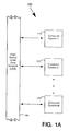
- Figure 1A is a block diagram showing a computer network including multiple computer systems coupled to each other for implementing the power management scheme of the present invention.
- Figure 1B shows one of the multi-module computer systems of Figure 1A.
- Figure 1C, 1D and 1E illustrate exemplary modules, a processor module, an I/O interface module, and a graphics module, respectively, of the multi-module computer system of Figure 1B.
- Figure 1F shows another one of the multi-module computer systems of Figure 1A.
- Figure 2 is a flow diagram showing a transition of the computer system from an awake state into a sleep state.
- Figure 3A and 3B are flow diagrams illustrating the processing of an asynchronous event and a deterministic event, respectively.
- Figure 3C is a flow diagram showing a transition the computer system from the sleep state into the awake state.
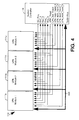
- Figures 4 is a block diagram of a four module computer system illustrating reset signals for powering up processor module(s) while preserving the states of the I/O interface module.
- Asynchronous event an event triggered externally with respect to the computer system.
- Deterministic event events triggered by the computer system, e.g., the expiration of an internal timer.
- Sleep state a state of the computer system where one or more of its modules are powered-down.
- Awake state a state of the computer system whereby all its modules are powered-up.
- Wakeup sequence a sequence executed by the computer system to transition from the sleep state into the awake state.
- Power-up sequence a sequence executed by a module to transition from a powered-down state into a powered-up state.
- Power-down sequence a sequence executed by a module to transition from a powered-up state into a powered-down state.
- I/O_Wakeup_Enable bit a control bit in an I/O interface module for inhibiting DMA requests from an I/O bus coupled to the I/O interface module. This bit causes the I/O interface module to issue an interrupt request (Int_Req) for a system controller. The system controller then wakes up the computer system by sending a reset signal to any powered-down module(s).
- the S_Sleep_Enter semaphore bit of the system controller provides an indicator that the computer system is in the process of entering the sleep state, and inhibits power up of the processor module(s) until the corresponding S_Wakeup_Enable semaphore bit is set.
- the setting of the S_Wakeup_Enable bit indicates that the processor module(s) of the computer system has completed the power-down sequence and it is now safe to initiate a power up of the processor module(s).
- Wakeup_Reset bit a status bit of the system controller for indicating that the cause of reset signal is a wakeup of the computer system, as opposed to a system-wide power on reset.
- a computer network 100 for implementing the power management scheme includes a local area network (LAN) 192 and a plurality of computer systems 110, 120, ... 170.
- LAN 192 provides a high speed data link between computer systems 110, 120, ... 170.
- computer systems can be coupled to each other by a wide variety of networking topologies including high speed local buses, local area network (LAN) such as ethernet, and wide area network (WAN) such as asynchronous transfer mode (ATM), and combinations of the above.
- LAN local area network
- WAN wide area network
- ATM asynchronous transfer mode
- computer systems 110, 120, ... 170 are similar and hence the following description of computer system 110 is applicable to computer systems 120, ... 170.
- computer system 110 includes a plurality of modules 111a, 111b, ... 111z, an interconnect (IC) 112, a system controller (SC) 114 and a main memory 115.
- Modules 111a, 111b, ... 111z are individually coupled to interconnect 112.
- Main memory 115 is also coupled to interconnect 112.
- Control lines couple system controller 114 to each of modules 111a, 111b, ... 111z, interconnect 112, and main memory 115.
- the plurality of modules 111a, 111b, ... 111z includes one or more processor module(s) and one or more input/output (I/O) interface module(s).
- module 111a is a processor module
- module 111b is an I/O interface module
- module 111z is a graphics interface module.
- Module 111b is coupled to LAN 192 via an I/O bus 116 and an I/O controller 118a.
- computer system 110 is a packet-switched and interconnect 112 is a datapath crossbar. Interconnect interfaces of modules 111a, 111b, ... 111z enable the modules to exchange data and control packets with each other via interconnect 112.
- computer system 110 is packet-switched, i.e., circuit-switched data lines are not required, the principles of the invention are also applicable to other non packet-switched systems.
- packet-switched i.e., circuit-switched data lines are not required
- the principles of the invention are also applicable to other non packet-switched systems.
- FIG. 1C illustrates exemplary processor module 111a of computer system 110.
- Processor module 111a includes an interconnect interface 111a2 and an optional local cache memory 111a1.
- interconnect interface 111a2 and an optional local cache memory 111a1.
- processor modules of computer network 100 are similar in structure, a description of the operation of processor module 111a is equally applicable to other processor modules of computer systems 110, 120,... 170.
- I/O bus 116 couples exemplary I/O interface module 111b to I/O controllers 118a, 118b, 118c, 118d of computer system 110.
- I/O controllers 118a, 118b, 118c, 118d provide interfaces for LAN 192, SCSI devices such as a hard disk drive 194, a keyboard 196 and an inactivity timer 198.
- Suitable system buses for implementing I/O bus 116 include the SBus and the PCI bus.
- computer system 110 is described as having one I/O interface module 111b, additional I/O interface modules can be added to computer system 110 for providing additional I/O capability, e.g., an ATM connection, an ISDN connection and a PCMCIA card.
- Figure 1E shows exemplary graphics interface module 111z of computer system 110.
- Module 111z is coupled to a graphics display device 195 via a graphics controller 119.
- Additional graphics controller(s) may be added for supporting additional graphics display devices.
- Graphics controller 119 may also control multiple graphics display devices.
- the power management scheme for computer network 100 of the present invention provides processor modules of computer systems 110, 120, ... 170 the ability to transparently enter and leave the sleep state while LAN 192 remains powered-up, thereby permitting computer network 100 to remain fully operational while reducing overall power consumption. This is possible because the respective I/O interface modules of computer systems 110, 120, ... 170 remain powered-up while one or more processor modules and selected peripheral devices are powered down when computer network 100 enter the sleep state; the rationale being processor modules typically consume the most power, along with peripheral devices such as disk drives and display monitors.
- the processor modules may be powered-down independently, the powered-down modules are powered up by a single reset signal of computer system 110. In other implementations, separate reset signals can be used for powering up individual modules.
- computer system 110 enters the sleep state under one of the following exemplary conditions.
- First, computer system 110 may enter the sleep state whenever it receives a time-out notification from inactivity timer 198.
- inactivity timer 198 Various criteria can be used by inactivity timer 198, such as inactivity of keyboard 196 or inactivity of user process(es) executing on processor module 111a.
- Second, computer system 110 can enter the sleep state upon completion of specific tasks.
- processor module 111a can initiate an entry by computer system 110 into the sleep state upon completion of house-keeping chore such as a periodic memory backup or a chronological task such as user accounting for charge backs.
- a network message may arrive at computer system 110 from a network manager via LAN 192 to computer system 110 initiating an entry into the sleep state.
- a user at computer system 110 may initiate an entry of computer system 110 into the sleep state by depressing a standby power switch.
- a brown-out/power-failure detector of computer system 110 may initiate an entry into the sleep state upon detecting an impeding shut-down of the primary power supply of computer system 110.
- Other conditions for entering the sleep state are possible since the topology of computer network 100, particularly computer system 110, advantageously permits both systems designers and end-users a great deal of flexibility in implementing different conditions for entering into the sleep state.
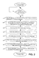
- FIG. 2 is a flow diagram illustrating steps executed by computer system 110 to enter the sleep state.
- processor module 111a sets an I/O_Wakeup_Enable status bit of I/O interface module 111b (step 210).
- I/O_Wakeup_Enable bit When the I/O_Wakeup_Enable bit is set, all direct memory access (DMA) arbitration on system bus 390 is inhibited, preventing any DMA to a potentially halted main memory 115. Consequently, any bus arbitration request for DMAs will trigger an interrupt request (Int_Req) for powering up processor module 111a.
- a DMA request from I/O interface module 111b will result in an Int_Req to system controller 114 for powering up processor module 111a to process the DMA.
- system controller 114 is responsible for policing traffic through interconnect 112 and for powering-up processor module 111a when the need arises.
- an S_Sleep_Enter semaphore bit of system controller 114 is set (step 220). Setting the S_Sleep_Enter bit ensures that processor module 111a can execute critical sections of the power down sequence without any power-up reset signals arriving at processor module 111a.
- the S_Sleep_Enter bit provides an indicator to system controller 114 that processor module 111a is in the process of being powered down and inhibits any attempt to power up processor module 111a until a second semaphore bit, the S_Wakeup_Enable bit, of system controller 114 is set by processor module 111a to indicate that module 111a has completed its power-down sequence and can now be powered-up.
- each module is coupled to a distributed system controller and a distributed memory.
- module 121a is coupled to distributed system controller 124a and distributed memory 125a.
- processor modules of modules 121a ... 121z can be individually powered down, with a separate semaphore bit pair, i.e., S_Sleep_Enter and S_Wakeup_Enable bits, provided for each processor module.
- Important state data of processor module 111a are then stored in stable memory, e.g., non-volative memory (step 230).
- the contents of local cache memory 111a1 are flushed into main memory 115 (step 240).
- the contents of main memory 115 can be copied onto hard drive 194 if powering down of the DRAMs in main memory 115 is supported (step 245).
- one processor module is responsible for initiating a power down of the shared resources of computer system 110, e.g., peripheral devices such as disk drive 194 and graphics display device 195 (step 250).
- peripheral devices such as disk drive 194 and graphics display device 195
- graphics controller 119 may halt the vertical/horizontal synchronization signals and blank the video signal to display device 195.
- display device 195 can be powered down.
- the second semaphore bit is set (step 260). Setting the S_Wakeup_Enable bit provides an indicator that processor 111a has completed its power-down sequence. System controller 114 can now generate a reset signal to power up processor module 111a.
- a ShutDown instruction is executed by processor module 111a thereby completing the entry of computer system 110 into the sleep state (step 270).
- a processor module e.g., processor module 111a
- the internal clock of processor module 111a is disabled in a manner consistent with the underlying semiconductor technology. For example, in CMOS technology, it is advantageous to be able to stop the internal processor clock to minimizing power consumption.
- processor module 111a when processor module 111a is powered-down, the main system clock of computer system 110 remains running while the internal processor clock of processor module 111a is suppressed internally by processor module 111a.
- data packets may be discarded at the network level, i.e., ignored by system controller 114. Although some network level packets may be lost, robust higher level protocols such as TCP may be capable of recovering from such a loss without losing the network connection, thereby providing end-to-end integrity of data packets transmitted by user applications executing on computer network 100.
- This advantageous aspect of the present invention provides computer systems 110, 120, ... 170 with the illusion of appearing to be "awake" while actually in the sleep state.
- the incoming data packets are buffered at I/O interface module 111b until the intended recipient of the data packet, e.g., processor module 111a, has been powered up.
- computer system 110 when computer system 110 is in the sleep state, computer system 110 can be awaken under pre-defined conditions called events.
- events There are two classes of events; namely deterministic events and asynchronous events. Note the following definitions of deterministic and asynchronous events are provided to better illustrate the various events since the transition of computer system 110 from the sleep state into the awake state in response to different events are similar.
- Deterministic events are events triggered internally by computer system 110.
- An example of a deterministic event is when computer system 110 needs to execute a housekeeping chore such as a daily back up of the contents of a hard drive onto magnetic tape, when an internal timer expires, e.g., at midnight.
- a housekeeping chore such as a daily back up of the contents of a hard drive onto magnetic tape
- an internal timer expires, e.g., at midnight.
- Such an event is deterministic because computer system 110 is the originator of the event and as such, controls the beginning and end of the housekeeping chore.
- processor module 111a is the "write-enabled" owner of a data structure whose most current copy is stored in local cache 111a1 of processor module 111a, and a second processor module of computer system 110 needs to read and then write over the data structure, such a read of the data structure initiated by the second processor module is also deterministic with respect to computer system 110.
- asynchronous events are events triggered by a source external to computer system 110.
- An example of an asynchronous event is the arrival of a network packet at network controller 118a and destined for a processor module of computer system 110.
- Another example of an asynchronous event is a user depressing a key on keyboard 196, or depressing a standby button of computer system 110.
- Figures 3A and 3B are flow diagrams illustrating the processing of an asynchronous event and a deterministic event, respectively.
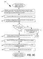
- Figure 3C is a flow diagram illustrating the wakeup sequence executed by computer system 110 to transition from the sleep state into the awake state.
- Figure 4 shows an implementation of computer system 110 illustrating a pair of reset signals for waking up computer system 110. The reset signals power up any powered-down module(s) among modules 111a, 111c, ... 111z while preserving the states of modules which remain powered-up, e.g., I/O interface module 111b.
- the two reset signals used by system controller 114 are the UPA_Reset and UPA_Arb_Reset signals; the UPA_Arb_Reset signal is provided to modules that are not powered down, e.g., I/O interface module 111b, while the UPA_Reset signal is provided to powered-down modules, e.g., processor module 111a and graphic module 111z. In other implementations, where only selected processor modules are powered down, the UPA_Arb_Reset signal is provided to processor module(s) that remain powered-up.
- I/O bus 116 drops any DMA request resulting from the asynchronous event (step 320).
- a corresponding interrupt request (Int_Req) is generated by I/O interface module 111b for system controller (SC) 114 (step 325).
- System controller 114 NACKs (negative acknowledgment) the Int_Req from I/O interface module 111b (step 330).
- System controller 114 sets the Wakeup_Reset bit and also asserts a Reset_Call bit to initiate a wakeup sequence for computer system 110 (step 340).
- I/O interface module 111b keeps resending Int_Req to SC 114 (step350).
- SC 114 responds by reNACKing (step 370) until computer system 110 has completed the wakeup sequence (step 360).
- the I/O_Wakeup_Enable bit is cleared to indicate that the processor module(s) of computer system 110 are now powered-up, e.g., processor module 111a is now powered up and is able process to the cause of the Int_Req.
- system controller 114 Upon completion of the wakeup sequence, system controller 114 sends an ACK to I/O interface module 111b and a corresponding interrupt packet to processor module 111a (step 380).
- Processor module 111a is now powered-up and able to handle the interrupt packet from SC 114 (step 390).
- Computer system 110 is now in the awake state.
- an Int_Req is generated for system controller 114 (step 322).
- System controller 114 NACKs the Int_Req (step 332).
- system controller 114 sets the Wakeup_Reset bit, and also asserts the Reset_Call bit to initiates a wakeup sequence for computer system 110 (step 340).
- system controller sends a corresponding interrupt packet to processor module 111a (step 382).
- Processor module 111a is powered-up and able to handle the interrupt packet, e.g., attend to the expiration of the timer (step 392).
- Computer system 110 is now in the awake state.
- reset signals are sent to processor module 111a in the following manner.
- system controller 114 asserts a request to become a master of system bus 490.
- SC 114 asserts the UPA_Arb_Reset signal for powered-up module(s), and UPA_Reset signal for powered-down module(s), e.g., I/O interface module 111b and processor module 111a, respectively (step 341).
- the UPA_Arb_Reset signal allows the powered-up modules to synchronize their internal arbitration state(s) i.e., selectively clear arbitration state(s), without completely clearing all its internal states.
- System controller 114 holds the UPA_Arb_Reset signal low for the same duration as UPA_Reset signal. Note that before de-asserting the UPA_Arb_Reset signal, SC 114 de-asserts its request for system bus 490, and resets its own internal arbitration state to update the respective status bits of processor modules 111a, 111c.
- processor module 111a executes a power-up boot sequence (step 342).
- the boot sequence code is located in a suitable non-volatile memory such as in a boot PROM.
- the Wakeup_Reset bit in system controller 114 is then polled to determine the cause of the reset signals (step 343).
- a powered-down module of computer system 110 e.g., processor module 111a
- module 111a is unaware of the origin or cause of the reset signal, i.e., whether the UPA_Reset signal was caused by a wakeup sequence or by a system-wide power-up sequence of computer system 110.
- the Wakeup_Reset bit is not set, computer system 110 executes a system-wide power-up sequence (step 345).
- the Wakeup_Reset bit is set, computer system 110 proceed with the execution of the wakeup sequence.
- addition states are provided, e.g., a "suspend” state, a "standby” state.
- the suspend state has a lower level of readiness than that of the sleep state.
- computer system 110 In the suspend state, computer system 110 is not network available, i.e., it appears to be sleeping with respect to the rest of computer network 100.
- the main power supply of computer system 110 is in a low power "standby" mode.
- a backup battery provides power to an alarm timer for waking computer system 110. Upon expiration of the alarm timer, the main power supply is re-enabled which wakes computer system 110 up.
- depressing a "power" key on keyboard 196 or a main on/off power switch also restarts computer system 110.
- the suspend state is useful for computer systems that need not be “network alive", i.e., appear awake all the time.
- the standby state of computer system 110 has a readiness level between that of the sleep state and the awake state. In the standby state, all processor modules remain awake while inactive peripheral devices, e.g., disk drive(s) and display device(s) are turned off or enter a low power mode.
- inactive peripheral devices e.g., disk drive(s) and display device(s) are turned off or enter a low power mode.
- the total number of processor modules within each computer system can be smaller or larger.
- the control functions provided by the system controller of each computer system can be distributed among the modules of each computer system.
- Other computer network configurations and hybrids of processor modules are also possible.
- clusters of multi-module computer systems may be coupled to each other by a variety of means including high speed buses. It is also possible for some processor modules to remain continuously powered up, and/or for some I/O interface modules which only control passive devices such as magnetic tape drives and laser disk drives to be powered down. Hence the scope of the invention should be determined by the following claims.
Landscapes
- Engineering & Computer Science (AREA)
- Theoretical Computer Science (AREA)
- Physics & Mathematics (AREA)
- General Engineering & Computer Science (AREA)
- General Physics & Mathematics (AREA)
- Power Sources (AREA)
- Multi Processors (AREA)
Applications Claiming Priority (2)
| Application Number | Priority Date | Filing Date | Title |
|---|---|---|---|
| US414879 | 1995-03-31 | ||
| US08/414,879 US5692197A (en) | 1995-03-31 | 1995-03-31 | Method and apparatus for reducing power consumption in a computer network without sacrificing performance |
Publications (3)
| Publication Number | Publication Date |
|---|---|
| EP0735455A2 true EP0735455A2 (de) | 1996-10-02 |
| EP0735455A3 EP0735455A3 (de) | 2000-04-19 |
| EP0735455B1 EP0735455B1 (de) | 2002-12-18 |
Family
ID=23643381
Family Applications (1)
| Application Number | Title | Priority Date | Filing Date |
|---|---|---|---|
| EP96302149A Expired - Lifetime EP0735455B1 (de) | 1995-03-31 | 1996-03-28 | Aktive Leistungssteuerung in einem Computersystem |
Country Status (5)
| Country | Link |
|---|---|
| US (1) | US5692197A (de) |
| EP (1) | EP0735455B1 (de) |
| JP (1) | JP3803418B2 (de) |
| CA (1) | CA2172774A1 (de) |
| DE (1) | DE69625405T2 (de) |
Cited By (5)
| Publication number | Priority date | Publication date | Assignee | Title |
|---|---|---|---|---|
| EP0973086A1 (de) * | 1998-07-15 | 2000-01-19 | Hewlett-Packard Company | Ferneineschaltung eines Rechners |
| GB2348524A (en) * | 1998-12-14 | 2000-10-04 | Ibm | Low power mode computer with simplified power supply |
| EP0936532A3 (de) * | 1998-02-13 | 2002-03-27 | Fujitsu Limited | Fernsteuerungsverfahren für Leistungssparfunktion |
| EP1223500A4 (de) * | 1999-09-20 | 2006-03-22 | Matsushita Electric Industrial Co Ltd | Steuergerät |
| EP1708411A1 (de) * | 2005-03-28 | 2006-10-04 | Canon Kabushiki Kaisha | Netzwerkgerät mit Energiesparmodus sowie zugehöriges Kontrollverfahren |
Families Citing this family (89)
| Publication number | Priority date | Publication date | Assignee | Title |
|---|---|---|---|---|
| IT1278526B1 (it) * | 1995-12-12 | 1997-11-24 | Eric Verheecke | Procedimento di automatizzazione di procedure informatiche e dispositivo per la sua attuazione |
| US5974552A (en) * | 1995-12-29 | 1999-10-26 | Samsung Electronics Co., Ltd. | Method and apparatus for executing a scheduled operation after wake up from power off state |
| JP3621497B2 (ja) * | 1996-03-01 | 2005-02-16 | 株式会社東芝 | コンピュータシステム及び同システムにおけるクロック停止信号制御方法 |
| JP3274608B2 (ja) * | 1996-07-12 | 2002-04-15 | 日本電気株式会社 | 携帯端末装置 |
| US5925131A (en) * | 1996-08-19 | 1999-07-20 | Compaq Computer Corporation | Computer and computer network having a power down inhibit |
| JP3039395B2 (ja) * | 1996-10-17 | 2000-05-08 | 日本電気株式会社 | 無線携帯端末における情報処理部の起動方式 |
| JP3763903B2 (ja) | 1996-10-29 | 2006-04-05 | 株式会社日立製作所 | 情報処理装置 |
| US5838982A (en) * | 1996-12-19 | 1998-11-17 | Intel Corporation | Power switch method and apparatus for preventing a failure in the power controller |
| US7031441B1 (en) * | 1996-12-30 | 2006-04-18 | Intel Corporation | Method and apparatus for supporting on-demand connectivity for network applications |
| EP0855718A1 (de) * | 1997-01-28 | 1998-07-29 | Hewlett-Packard Company | Speichersteuerung in niedrigem Verbrauchsmodus |
| US6260111B1 (en) * | 1997-08-15 | 2001-07-10 | International Business Machines Corporation | System and method for network power management incorporating user identity and preferences via a power managed smart card |
| US5938771A (en) * | 1997-10-30 | 1999-08-17 | Advanced Micro Devices, Inc. | Apparatus and method in a network interface for enabling power up of a host computer using magic packet and on-now power up management schemes |
| US6308278B1 (en) * | 1997-12-29 | 2001-10-23 | Intel Corporation | Supplying standby voltage to memory and wakeup circuitry to wake a computer from a low power mode |
| US6131167A (en) * | 1997-12-31 | 2000-10-10 | Intel Corporation | Method and apparatus to reduce power consumption on a bus |
| US6065122A (en) * | 1998-03-13 | 2000-05-16 | Compaq Computer Corporation | Smart battery power management in a computer system |
| US6895448B2 (en) | 1998-03-26 | 2005-05-17 | O2 Micro, Inc. | Low-power audio CD player for portable computers |
| US6954804B2 (en) * | 1998-03-26 | 2005-10-11 | Micro, Inc. | Controller for portable electronic devices |
| US6675233B1 (en) * | 1998-03-26 | 2004-01-06 | O2 Micro International Limited | Audio controller for portable electronic devices |
| JP3236563B2 (ja) * | 1998-06-19 | 2001-12-10 | ファナック株式会社 | 制御装置 |
| US6292890B1 (en) * | 1998-09-29 | 2001-09-18 | Compaq Computer Corporation | Computer system with dynamically configurable boot order |
| US7206849B1 (en) * | 1998-10-05 | 2007-04-17 | Symbol Technologies, Inc. | Communication in a wireless communications network when a mobile computer terminal may be unreachable |
| US6212645B1 (en) * | 1998-10-09 | 2001-04-03 | Mediaq Inc. | Programmable and flexible power management unit |
| US6088806A (en) * | 1998-10-20 | 2000-07-11 | Seiko Epson Corporation | Apparatus and method with improved power-down mode |
| US6604201B1 (en) | 1998-10-28 | 2003-08-05 | Matsushita Electric Industrial Co., Ltd. | Network unit with power saving mode inhibit based on interconnection relationship to neighboring nodes which is stored on the unit |
| US6233692B1 (en) * | 1998-12-02 | 2001-05-15 | Intel Corporation | Power share controller for providing continuous system peripheral bay access between at least two data processing systems on a data network with no interruption to peripheral bay operation |
| KR100572307B1 (ko) * | 1998-12-04 | 2006-08-14 | 삼성전자주식회사 | 전원 관리 기능을 구비한 컴퓨터 시스템 |
| US6523124B1 (en) * | 1999-04-23 | 2003-02-18 | Palm, Inc. | System and method for detection of an accessory device connection status |
| US6467041B1 (en) * | 1999-05-06 | 2002-10-15 | International Business Machines Corporation | Third party host packet replication |
| US6393570B1 (en) * | 1999-05-28 | 2002-05-21 | 3Com Corporation | Low-power apparatus for power management enabling |
| US6587950B1 (en) * | 1999-12-16 | 2003-07-01 | Intel Corporation | Cluster power management technique |
| US6499102B1 (en) * | 1999-12-29 | 2002-12-24 | Intel Corporation | Method of dynamically changing the lowest sleeping state in ACPI |
| US6701442B1 (en) | 2000-05-09 | 2004-03-02 | 3Com Corporation | Power management circuit for selectively applying power to network monitoring circuitry which monitors the receipt of network wake-up messages |
| US7818443B2 (en) * | 2000-12-01 | 2010-10-19 | O2Micro International Ltd. | Low power digital audio decoding/playing system for computing devices |
| US7526349B2 (en) * | 2000-12-01 | 2009-04-28 | O2Micro International Limited | Low power digital audio decoding/playing system for computing devices |
| US7522964B2 (en) | 2000-12-01 | 2009-04-21 | O2Micro International Limited | Low power digital audio decoding/playing system for computing devices |
| US7522966B2 (en) * | 2000-12-01 | 2009-04-21 | O2Micro International Limited | Low power digital audio decoding/playing system for computing devices |
| US7522965B2 (en) | 2000-12-01 | 2009-04-21 | O2Micro International Limited | Low power digital audio decoding/playing system for computing devices |
| US7890741B2 (en) * | 2000-12-01 | 2011-02-15 | O2Micro International Limited | Low power digital audio decoding/playing system for computing devices |
| JP2002268778A (ja) * | 2001-03-14 | 2002-09-20 | Toshiba Corp | 情報処理装置 |
| US20020169680A1 (en) * | 2001-05-10 | 2002-11-14 | International Business Machines Corporation | Method and apparatus for building commercial distributed computing networks via computer cost subsidization |
| US7139922B2 (en) * | 2001-07-30 | 2006-11-21 | Intel Corporation | Powering down a computer in response to a thermal event |
| US6993571B2 (en) * | 2001-08-16 | 2006-01-31 | International Business Machines Corporation | Power conservation in a server cluster |
| US7337333B2 (en) * | 2001-09-19 | 2008-02-26 | Dell Products L.P. | System and method for strategic power supply sequencing in a computer system with multiple processing resources and multiple power supplies |
| US7111179B1 (en) | 2001-10-11 | 2006-09-19 | In-Hand Electronics, Inc. | Method and apparatus for optimizing performance and battery life of electronic devices based on system and application parameters |
| US20030079151A1 (en) * | 2001-10-18 | 2003-04-24 | International Business Machines Corporation | Energy-aware workload distribution |
| US7017052B2 (en) * | 2001-11-16 | 2006-03-21 | Lenovo Pte. Ltd. | Method and system for reducing boot time for a computer |
| US6685334B2 (en) | 2002-04-30 | 2004-02-03 | G-5 Electronics | System and method of power management for a solar powered device |
| US6924667B2 (en) * | 2002-07-19 | 2005-08-02 | O2Micro International Limited | Level shifting and level-shifting amplifier circuits |
| US20050102457A1 (en) * | 2003-11-12 | 2005-05-12 | Dell Products L.P. | System and method for interrupt processing in a multiple processor system |
| US7937557B2 (en) | 2004-03-16 | 2011-05-03 | Vns Portfolio Llc | System and method for intercommunication between computers in an array |
| US7366921B2 (en) * | 2004-04-23 | 2008-04-29 | Hewlett-Packard Development Company, L.P. | Selecting input/output devices to control power consumption of a computer system |
| JP4465598B2 (ja) | 2004-07-05 | 2010-05-19 | ソニー株式会社 | 集積回路およびその処理制御方法、並びに、プログラム |
| US7251726B2 (en) * | 2004-09-09 | 2007-07-31 | Hewlett-Packard Development Company, L.P. | Multiple functionality associated with a computer ON/OFF pushbutton switch |
| JP4666990B2 (ja) * | 2004-09-30 | 2011-04-06 | 株式会社日本デジタル研究所 | ネットワークraidシステム |
| US7636861B2 (en) * | 2005-01-27 | 2009-12-22 | Hewlett-Packard Development Company, L.P. | Bus technique for controlling power states of blades in a blade enclosure |
| TWI326043B (en) * | 2005-09-05 | 2010-06-11 | Hon Hai Prec Ind Co Ltd | The system, method and electrical apparatus for data transferring |
| US7966481B2 (en) | 2006-02-16 | 2011-06-21 | Vns Portfolio Llc | Computer system and method for executing port communications without interrupting the receiving computer |
| EP1821174B9 (de) * | 2006-02-16 | 2010-10-27 | VNS Portfolio LLC | Asynchroner stromsparender Computer |
| US7617383B2 (en) * | 2006-02-16 | 2009-11-10 | Vns Portfolio Llc | Circular register arrays of a computer |
| US7904615B2 (en) | 2006-02-16 | 2011-03-08 | Vns Portfolio Llc | Asynchronous computer communication |
| US8151126B2 (en) * | 2006-06-29 | 2012-04-03 | Arm Limited | Controlling power consumption in a data processing apparatus |
| CN101206517B (zh) * | 2006-12-22 | 2011-06-22 | 群康科技(深圳)有限公司 | 电脑 |
| US7734942B2 (en) * | 2006-12-28 | 2010-06-08 | Intel Corporation | Enabling idle states for a component associated with an interconnect |
| US8125936B2 (en) * | 2007-03-08 | 2012-02-28 | Marvell International Ltd. | Low power data streaming |
| US7555637B2 (en) * | 2007-04-27 | 2009-06-30 | Vns Portfolio Llc | Multi-port read/write operations based on register bits set for indicating select ports and transfer directions |
| KR20090032415A (ko) * | 2007-09-28 | 2009-04-01 | 삼성전자주식회사 | 프로세서 웨이크 업 기능을 갖는 멀티포트 반도체 메모리장치 및 이를 채용한 멀티 프로세서 시스템 그리고 멀티프로세서 시스템에서의 프로세서 웨이크 업 방법 |
| US20090222832A1 (en) * | 2008-02-29 | 2009-09-03 | Dell Products, Lp | System and method of enabling resources within an information handling system |
| US20100023730A1 (en) * | 2008-07-24 | 2010-01-28 | Vns Portfolio Llc | Circular Register Arrays of a Computer |
| US20100033433A1 (en) * | 2008-08-08 | 2010-02-11 | Dell Products, Lp | Display system and method within a reduced resource information handling system |
| US8134565B2 (en) * | 2008-08-08 | 2012-03-13 | Dell Products, Lp | System, module and method of enabling a video interface within a limited resource enabled information handling system |
| US8108582B2 (en) * | 2008-08-27 | 2012-01-31 | Hewlett-Packard Development Company, L.P. | Notifying asynchronous events to a host of a data storage system and apparatus for the same |
| US8370673B2 (en) * | 2008-10-30 | 2013-02-05 | Dell Products, Lp | System and method of utilizing resources within an information handling system |
| US8533506B2 (en) * | 2010-06-04 | 2013-09-10 | Lenovo (Singapore) Pte. Ltd. | System wakeup on wireless network messages |
| US8751843B2 (en) | 2008-12-16 | 2014-06-10 | The Regents Of The University Of Michigan | Computer energy conservation with a scalable PSU configuration |
| WO2010149216A1 (en) * | 2009-06-26 | 2010-12-29 | Nokia Siemens Networks Oy | Wake up procedure for a base station in a communications network |
| US8392732B2 (en) | 2010-04-16 | 2013-03-05 | Comcast Cable Communications, Llc | Systems, apparatuses, and methods to monitor signals received by a paging monitor to detect an activity trigger |
| US9285856B2 (en) * | 2010-12-21 | 2016-03-15 | Qualcomm Incorporated | Method and system for rapid entry into and for rapid exiting from sleep states for processors of a portable computing device |
| US9104499B2 (en) | 2010-12-21 | 2015-08-11 | Qualcomm Incorporated | System for minimizing resource latency between processor application states in a portable computing device by scheduling resource state set transitions |
| US10324430B2 (en) | 2011-02-09 | 2019-06-18 | Vertiv It Systems, Inc. | Infrastructure control fabric system and method |
| US9715222B2 (en) * | 2011-02-09 | 2017-07-25 | Avocent Huntsville, Llc | Infrastructure control fabric system and method |
| US8732506B2 (en) | 2011-05-26 | 2014-05-20 | Cisco Technology, Inc. | Method and apparatus for providing power to a server platforms by using a capacitor to provide power during a second power supply transitioning on |
| JP5917031B2 (ja) * | 2011-07-04 | 2016-05-11 | サイプレス セミコンダクター コーポレーション | マイクロコンピュータ |
| ES2663745T3 (es) | 2011-08-23 | 2018-04-16 | Philips Lighting Holding B.V. | Sistema de iluminación que comprende una unidad maestra y unidades esclavas en donde la unidad maestra puede moverse a un modo de reposo con una unidad esclava como maestra |
| US8954980B2 (en) | 2011-11-11 | 2015-02-10 | Qualcomm Incorporated | Conserving power through work load estimation for a portable computing device using scheduled resource set transitions |
| US9250685B2 (en) | 2012-11-05 | 2016-02-02 | Comcast Cable Communications, Llc | Remotely waking a sleeping device using a wake configuration file |
| US9471132B2 (en) * | 2013-09-27 | 2016-10-18 | Intel Corporation | Techniques for putting platform subsystems into a lower power state in parallel |
| DE102014215075A1 (de) * | 2014-07-31 | 2016-02-04 | Siemens Aktiengesellschaft | Steuerung mindestens eines Rechners eines Schienenfahrzeugs |
| JP5892349B1 (ja) * | 2014-11-21 | 2016-03-23 | パナソニックIpマネジメント株式会社 | 無線通信装置およびその制御方法 |
| CN113448907B (zh) * | 2021-08-31 | 2021-12-21 | 北京智联安科技有限公司 | 一种低功耗串行异步收发器及数据接收方法、介质 |
Family Cites Families (10)
| Publication number | Priority date | Publication date | Assignee | Title |
|---|---|---|---|---|
| US5287537A (en) * | 1985-11-15 | 1994-02-15 | Data General Corporation | Distributed processing system having plural computers each using identical retaining information to identify another computer for executing a received command |
| US4980836A (en) * | 1988-10-14 | 1990-12-25 | Compaq Computer Corporation | Apparatus for reducing computer system power consumption |
| EP0415376A3 (en) * | 1989-08-28 | 1992-04-08 | Kabushiki Kaisha Toshiba | Computer unit with a resume function |
| US5148380A (en) * | 1990-08-27 | 1992-09-15 | Acer Incorporated | Method and apparatus for conserving power in a data processing system |
| EP0508685A3 (en) * | 1991-04-10 | 1992-12-23 | International Business Machines Corporation | Power-on control system for a computer |
| US5432946A (en) * | 1991-04-11 | 1995-07-11 | International Business Machines Corp. | LAN server personal computer with unattended activation capability |
| US5303171A (en) * | 1992-04-03 | 1994-04-12 | Zenith Data Systems Corporation | System suspend on lid close and system resume on lid open |
| US5283905A (en) * | 1991-06-24 | 1994-02-01 | Compaq Computer Corporation | Power supply for computer system manager |
| US5497494A (en) * | 1993-07-23 | 1996-03-05 | International Business Machines Corporation | Method for saving and restoring the state of a CPU executing code in protected mode |
| US5381414A (en) * | 1993-11-05 | 1995-01-10 | Advanced Micro Devices, Inc. | Method and apparatus for determining if a data packet is addressed to a computer within a network |
-
1995
- 1995-03-31 US US08/414,879 patent/US5692197A/en not_active Expired - Lifetime
-
1996
- 1996-03-27 CA CA002172774A patent/CA2172774A1/en not_active Abandoned
- 1996-03-28 DE DE69625405T patent/DE69625405T2/de not_active Expired - Fee Related
- 1996-03-28 EP EP96302149A patent/EP0735455B1/de not_active Expired - Lifetime
- 1996-03-29 JP JP09959796A patent/JP3803418B2/ja not_active Expired - Lifetime
Cited By (8)
| Publication number | Priority date | Publication date | Assignee | Title |
|---|---|---|---|---|
| EP0936532A3 (de) * | 1998-02-13 | 2002-03-27 | Fujitsu Limited | Fernsteuerungsverfahren für Leistungssparfunktion |
| EP0973086A1 (de) * | 1998-07-15 | 2000-01-19 | Hewlett-Packard Company | Ferneineschaltung eines Rechners |
| US6453423B1 (en) | 1998-07-15 | 2002-09-17 | Hewlett-Packard Company | Computer remote power on |
| GB2348524A (en) * | 1998-12-14 | 2000-10-04 | Ibm | Low power mode computer with simplified power supply |
| US6415387B1 (en) | 1998-12-14 | 2002-07-02 | International Business Machines Corporation | Low power mode computer with simplified power supply |
| EP1223500A4 (de) * | 1999-09-20 | 2006-03-22 | Matsushita Electric Industrial Co Ltd | Steuergerät |
| EP1708411A1 (de) * | 2005-03-28 | 2006-10-04 | Canon Kabushiki Kaisha | Netzwerkgerät mit Energiesparmodus sowie zugehöriges Kontrollverfahren |
| CN100446474C (zh) * | 2005-03-28 | 2008-12-24 | 佳能株式会社 | 网络设备和控制网络设备的方法 |
Also Published As
| Publication number | Publication date |
|---|---|
| DE69625405D1 (de) | 2003-01-30 |
| US5692197A (en) | 1997-11-25 |
| EP0735455A3 (de) | 2000-04-19 |
| EP0735455B1 (de) | 2002-12-18 |
| JPH0934601A (ja) | 1997-02-07 |
| JP3803418B2 (ja) | 2006-08-02 |
| DE69625405T2 (de) | 2003-08-14 |
| CA2172774A1 (en) | 1996-10-01 |
Similar Documents
| Publication | Publication Date | Title |
|---|---|---|
| US5692197A (en) | Method and apparatus for reducing power consumption in a computer network without sacrificing performance | |
| EP1099167B1 (de) | Verfahren und gerät zum strommodus-übergang in einem multigewinde-prozessor | |
| US6782472B2 (en) | Method of initializing a memory controller by executing software in a second memory to wake up a system | |
| US7100062B2 (en) | Power management controller and method | |
| US6243831B1 (en) | Computer system with power loss protection mechanism | |
| US6760850B1 (en) | Method and apparatus executing power on self test code to enable a wakeup device for a computer system responsive to detecting an AC power source | |
| EP0662652B1 (de) | Verfahren und Vorrichtung zur Reduzierung der Leistungsaufnahme in einem Rechnersystem | |
| US6711691B1 (en) | Power management for computer systems | |
| US20030159076A1 (en) | Keyboard controller providing power management for a portable computer system | |
| US6125450A (en) | Stop clock throttling in a computer processor through disabling bus masters | |
| TWI298436B (en) | An operation method in an apparatus, an electronic system therefor, and a computer readable medium therefor | |
| CN102037428A (zh) | 具有用于提供降低电源消耗的睡眠状态的次要存储器控制器的集成电路及方法 | |
| JPH07230347A (ja) | Scsiディスクドライブパワーダウン装置 | |
| JPH0836445A (ja) | コンピュータシステムのための電力管理システム | |
| JPH10228340A (ja) | 電子装置 | |
| CN101013340A (zh) | 一种降低无线网卡功耗的方法 | |
| JPH11288334A (ja) | コンピュータ・システムのパワーダウン方法及び装置 | |
| CN1584847B (zh) | 在交流电源不存在时的操作状态保存的方法和系统 | |
| US6477655B1 (en) | System and method to set PME—status bit and wake up the system, and selectively load device driver by searching who set the bit without requiring clock | |
| CN1327344C (zh) | 无交流电源时保存和恢复工作状态的基本输入/输出系统 | |
| US8832483B1 (en) | System-on-chip with power-save mode processor | |
| EP1656602A1 (de) | Netztaste und einrichtungs-aufweckereignisverarbeitungsverfahren bei abwesenheit von wechselstromversorgung | |
| CN120762520B (zh) | 一种上下电控制系统、方法及存储介质 | |
| JP2000112580A (ja) | コンピュータシステムおよびそのウェイクアップ制御方法 | |
| TW202526579A (zh) | 電源管理系統與電腦設備 |
Legal Events
| Date | Code | Title | Description |
|---|---|---|---|
| PUAI | Public reference made under article 153(3) epc to a published international application that has entered the european phase |
Free format text: ORIGINAL CODE: 0009012 |
|
| AK | Designated contracting states |
Kind code of ref document: A2 Designated state(s): DE GB |
|
| PUAL | Search report despatched |
Free format text: ORIGINAL CODE: 0009013 |
|
| AK | Designated contracting states |
Kind code of ref document: A3 Designated state(s): DE GB |
|
| 17P | Request for examination filed |
Effective date: 20001019 |
|
| 17Q | First examination report despatched |
Effective date: 20010308 |
|
| GRAG | Despatch of communication of intention to grant |
Free format text: ORIGINAL CODE: EPIDOS AGRA |
|
| GRAG | Despatch of communication of intention to grant |
Free format text: ORIGINAL CODE: EPIDOS AGRA |
|
| GRAG | Despatch of communication of intention to grant |
Free format text: ORIGINAL CODE: EPIDOS AGRA |
|
| GRAH | Despatch of communication of intention to grant a patent |
Free format text: ORIGINAL CODE: EPIDOS IGRA |
|
| GRAH | Despatch of communication of intention to grant a patent |
Free format text: ORIGINAL CODE: EPIDOS IGRA |
|
| GRAA | (expected) grant |
Free format text: ORIGINAL CODE: 0009210 |
|
| AK | Designated contracting states |
Kind code of ref document: B1 Designated state(s): DE GB |
|
| REG | Reference to a national code |
Ref country code: GB Ref legal event code: FG4D |
|
| REF | Corresponds to: |
Ref document number: 69625405 Country of ref document: DE Date of ref document: 20030130 Kind code of ref document: P Ref document number: 69625405 Country of ref document: DE Date of ref document: 20030130 |
|
| PLBE | No opposition filed within time limit |
Free format text: ORIGINAL CODE: 0009261 |
|
| STAA | Information on the status of an ep patent application or granted ep patent |
Free format text: STATUS: NO OPPOSITION FILED WITHIN TIME LIMIT |
|
| 26N | No opposition filed |
Effective date: 20030919 |
|
| PGFP | Annual fee paid to national office [announced via postgrant information from national office to epo] |
Ref country code: DE Payment date: 20070322 Year of fee payment: 12 |
|
| PG25 | Lapsed in a contracting state [announced via postgrant information from national office to epo] |
Ref country code: DE Free format text: LAPSE BECAUSE OF NON-PAYMENT OF DUE FEES Effective date: 20081001 |
|
| PGFP | Annual fee paid to national office [announced via postgrant information from national office to epo] |
Ref country code: GB Payment date: 20150325 Year of fee payment: 20 |
|
| REG | Reference to a national code |
Ref country code: GB Ref legal event code: PE20 Expiry date: 20160327 |
|
| PG25 | Lapsed in a contracting state [announced via postgrant information from national office to epo] |
Ref country code: GB Free format text: LAPSE BECAUSE OF EXPIRATION OF PROTECTION Effective date: 20160327 |