EP0735511A2 - Verfahren und Vorrichtung zum Ändern einer bestimmten Farbe in einem Farbbilde - Google Patents
Verfahren und Vorrichtung zum Ändern einer bestimmten Farbe in einem Farbbilde Download PDFInfo
- Publication number
- EP0735511A2 EP0735511A2 EP96103981A EP96103981A EP0735511A2 EP 0735511 A2 EP0735511 A2 EP 0735511A2 EP 96103981 A EP96103981 A EP 96103981A EP 96103981 A EP96103981 A EP 96103981A EP 0735511 A2 EP0735511 A2 EP 0735511A2
- Authority
- EP
- European Patent Office
- Prior art keywords
- color
- vector
- vectors
- subject
- substitute
- Prior art date
- Legal status (The legal status is an assumption and is not a legal conclusion. Google has not performed a legal analysis and makes no representation as to the accuracy of the status listed.)
- Withdrawn
Links
Images


Classifications
-
- G—PHYSICS
- G06—COMPUTING OR CALCULATING; COUNTING
- G06T—IMAGE DATA PROCESSING OR GENERATION, IN GENERAL
- G06T11/00—Two-dimensional [2D] image generation
- G06T11/10—Texturing; Colouring; Generation of textures or colours
Definitions
- the present invention relates to a method of and an apparatus for selectively changing a specified color of an image part included in a color image into another desired color.
- the process of preparing a cutout mask requires a substantial time and labor.
- the conventional method accordingly requires much time and labor in preparing a cutout mask prior to the actual color change process.
- An object of the present invention is thus to provide a method of and an apparatus for executing an actual color change process without preparing any cutout masks.
- the present invention is directed to a method of changing a color in a color image into another color.
- the method comprises the steps of: (a) specifying first and second colors for defining a color range to be processed by color change operation; (b) specifying a substitute color, which is to be used as a color component of a changed color after the color change operation; (c) obtaining first and second color vectors representing the first and second colors in a color space; (d) obtaining a substitute color vector representing the substitute color in the color space; (e) obtaining a third color vector linearly independent of the first and second color vectors; (f) expressing a color of each pixel in the color image by a linear combination of the first through third color vectors, to thereby obtain first through third coefficients for the first through third color vectors; and (g) if the first coefficient for a current pixel is positive, executing the color change operation through combing the substitute color vector, the second color vector, and the third color vector while using the first through third coefficients as weighting factors,
- the color change operation can be readily executed without preparing any masks.
- the step (g) comprises the step of executing the color change operation only if the first and second coefficients are both positive for the current pixel.
- the third color vector represents white in the preferred embodiment.
- the step (e) comprises the steps of: transforming the first and second color vectors to fourth and fifth color vectors in a hue/saturation/brightness space; and selecting a vector representing white in the color space as the third color vector when saturation components of the fourth and fifth color vectors are more than a predetermined value; and when a saturation component of at least one of the fourth and fifth color vectors is less than the predetermined value, rotating a hue component of one the fourth and fifth color vectors, whose saturation component is the greater, by a predetermined angle in the hue/saturation/brightness space to generate a sixth color vector and transforming the sixth color vector into the color space to generate the third color vector.
- the target color of color change operation is selected depending upon the hue of each pixel, and the hue component of the target color can be changed accordingly.
- the method comprises the steps of: (a) specifying a subject color and a pair of adjoining non-subject colors for defining a color range to be processed by color change operation; (b) specifying a substitute color, which is to be used as a color component of a changed color after the color change operation; (c) obtaining a first color vector representing the first color in a color space, and a pair of second color vectors representing the pair of adjoining non-subject colors; (d) obtaining a substitute color vector representing the substitute color in the color space; (e) successively selecting one of the pair of second color vectors, and obtaining a third color vector linearly independent of the first color vector and the selected second color vector, to thereby obtain a pair of vector combinations each including the first vector, the selected second vector, and the third vector; (f) selecting one of the pair of vector combinations, and expressing a color of each pixel in the color image by a linear combination of three color vectors included in the selected vector combination, to thereby obtain
- the color including both components of the target color and either one of the pair of adjoining non-target colors can be selected as a target of color change operation.
- the step (a) comprises the steps of: specifying a plurality of candidate colors as candidates for the pair of adjoining non-subject colors; and selecting two of the plurality of candidate colors, as the pair of adjoining non-subject colors, whose hue component vectors have the smallest angle which includes a hue component vector of the subject color.
- a color range defined by the pair of adjoining non-target colors on the hue ring can be selected as a target of color change operation. This allows the user to easily specify the target range of color change operation.
- the step (f) comprises the steps of: successively selecting one of the pair of vector combinations; obtaining the first through third coefficients for the three color vectors included in the selected vector combination; and providing the first through third coefficients for the selected vector combination to be used in the step (g) only if the first and second coefficients are both positive for the selected vector combination.
- the target range of color change operation can be determined based on the signs of the first and second coefficients. This desirably simplifies the process of color change operation.
- the present invention is further directed to an apparatus of changing a color in a color image into another color.
- the apparatus comprises: means for specifying first and second colors for defining a color range to be processed by color change operation, and a substitute color, which is to be used as a color component of a changed color after the color change operation; means for obtaining first and second color vectors representing the first and second colors in a color space; means for obtaining a substitute color vector representing the substitute color in the color space; computation means for obtaining a third color vector linearly independent of the first and second color vectors; means for expressing a color of each pixel in the color image by a linear combination of the first through third color vectors, to thereby obtain first through third coefficients for the first through third color vectors; and color changing means for, if the first coefficient for a current pixel is positive, executing the color change operation through combing the substitute color vector, the second color vector, and the third color vector while using the first through third coefficients as weighting factors, respectively, to thereby produce a changed
- the apparatus comprises: means for specifying a subject color and a pair of adjoining non-subject colors for defining a color range to be processed by color change operation, and a substitute color, which is to be used as a color component of a changed color after the color change operation; means for obtaining a first color vector representing the first color in a color space, and a pair of second color vectors representing the pair of adjoining non-subject colors; means for obtaining a substitute color vector representing the substitute color in the color space; computation means for successively selecting one of the pair of second color vectors, and obtaining a third color vector linearly independent of the first color vector and the selected second color vector, to thereby obtain a pair of vector combinations each including the first vector, the selected second vector, and the third vector; coefficient operation means for selecting one of the pair of vector combinations, and expressing a color of each pixel in the color image by a linear combination of three color vectors included in the selected vector combination, to thereby obtain first through third coefficients for the three color vector
- Fig. 1 illustrates an original color image which is a target of color change process in a first embodiment according to the present invention.
- the original color image is a photograph in which a model with black hair puts on yellow cloths with rose patterns.
- the rose patterns include white and pink petals and green leaves surrounding the petals. The following description will show a color change process of changing yellow, the background color of the cloths, into red.
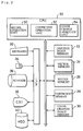
- Fig. 2 is a block diagram illustrating an image processing system applied for executing a color change process in the first embodiment of the invention.
- the image processing system is constructed as a computer system including a CPU 20, an original image memory 22 for storing an original color image, a vector memory 24 for storing components of color vectors, a matrix memory 26 for storing a matrix, which will be described later, a coefficient memory 28 for storing coefficients assigned to the color vectors, and a color-changed image memory 30 for storing a processed image after the color change process.
- the system is further provided with a keyboard 32 and a mouse 34 functioning as input means or specification means, a scanner 36 as image input means, a color CRT 38 as display means, and a hard disk drive 40 as external storage means.
- the CPU 20 implements functions of a matrix operation unit 50, a coefficient operation unit 52, and a color change operation unit 54.
- the CPU 20 executes software programs stored in a RAM (not shown) to implement these functions, which will be described below in detail.
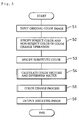
- Fig. 3 is a flowchart showing a general routine of color change process in the first embodiment.
- image data representing an original color image are captured by the scanner 36 and stored in the original image memory 22.
- the original color image is, for example, a color photograph as shown in Fig. 1.
- the original image memory 22 includes a frame memory, and the image stored in the original image memory 22 is displayed on the color CRT 38.
- the user specifies one subject color of the color change process and one non-subject color at step S2, and then specifies one substitute color at step S3.
- the subject color and the non-subject color define a target color range which is to be processed by the color change process, as will be described later in detail.
- the substitute color will substitute for the subject color in the color change process.
- yellow the background color of the clothes
- green the non-subject color while red is specified as the substitute color.
- the user can specify the colors by indicating one point in the color image displayed on the color CRT 38 with a pointing device, such as the mouse 34.
- the substitute color may be an arbitrary color not included in the original color image.
- the subject color and the non-subject color correspond to the "first color” and the “second color” of the invention, respectively.
- a variety of known methods can be applied in specifying the subject, non-subject and substitute colors.
- a plurality of points representing close colors are specified, and an average of the close colors is obtained to determine the subject color.
- the non-subject color and the substitute color can be determined in the same manner.
- Another possible method utilizes a color picker (sometimes called a color guide) , which is generally used for picking up arbitrary colors, to determine the subject color, the non-subject color, and the substitute color.
- Fig. 4 shows the positions of the subject color, the non-subject color, and the subject color on the Munsell's hue ring.
- the subject color and the non-subject color and the substitute will not be referred to by their specific colors, such as yellow, green and red, so as to generally explain the color change process.
- the matrix operation unit 50 calculates color vectors representing the subject color, the non-subject color, and the substitute color to obtain a matrix including those color vectors.
- the matrix will be explained later in detail.
- Fig. 5 is a flowchart showing details of step S4.
- the matrix operation unit 50 normalizes a color vector representing the subject color to determine a first color vector, and normalizes another color vector representing the non-subject color to determine a second color vector.
- Fig. 6 is a graph showing the first color vector for the subject color and the second color vector for the non-subject color.
- a color vector representing a subject color C sub is given by Vsub(R1,G1,B1), where (R1,G1,B1) respectively denote R (Red), G (Green), and B (Blue) components of the subject color C sub .
- the G axis of the RGB color space is omitted in Fig. 6.
- the matrix operation unit 50 determines a unit vector V1(r1,g1,b1) of the color vector Vsub and stores the components (r1,g1,b1) of the unit vector in the vector memory 24.
- the unit vector denotes a vector whose length is equal to one.
- the matrix operation unit 50 also determines a unit vector V2(r2,g2,b2) of a color vector Vnsub(R2,G2,B2) representing the non-subject color and stores the components (r2,g2,b2) of the unit vector in the vector memory 24 in the same manner.
- step S12 a normalized color vector Vrep for the substitute color is obtained in the same manner as in step S11.
- the first color vector V1 and the second color vector V2 thus obtained represent two of three vectors constituting a basis for expressing colors in the RGB space.
- a unit vector independent of the first and second color vector V1 and V2 is selected as a third color vector V3 for constructing the basis.
- the third color vector V3 is a unit vector which is not a linear combination of the first and second color vectors V1 and V2.
- a unit vector V WH representing 'white' can be selected as the third color vector V3.
- the unit vector V WH representing white has components of ( 1 ⁇ 3 , 1 ⁇ 3 , 1 ⁇ 3 ).
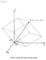
- Fig. 7 shows the first through third color vectors V1, V2, and V3 in the RGB space.
- linearly independent three color vectors V1, V2, and V3 define a basis of the color space.
- Any color E(Re,Ge,Be) in the color space can be expressed as a linear combination of the three color vectors V1, V2, and V3 as given by Equation (1):
- step S14 it is determined whether either one of the first color vector V1 and the second color vector V2 is sufficiently close to the unit white vector V WH ( 1 ⁇ 3 , 1 ⁇ 3 , 1 ⁇ 3 ).
- the process proceeds to step S14 at which another vector other than the unit vector V WH is determined as the third color vector V3.
- the first color vector V1 and the second color vector V2 are transformed to vectors in an HSV coordinate system, or Hue/Saturation/Brightness system, according to Equations (4a)-(4e):
- MAX max(r, g, b)
- MIN min(r, g, b)
- H arctan ⁇ ⁇ 3 (g - b) (r - g) + (r - b) ⁇
- V MAX + MIN 2
- S MAX - MIN
- Fig. 8 shows the HSV space, where the unit vector V WH representing white exists on the coordinate axis of brightness V. This means that the unit white vector V WH does not have either the saturation S or the hue H.
- the HSV space is a cylindrical polar coordinate system or zr ⁇ coordinate system, where the brightness V corresponds to a vertical coordinate z, the saturation S to a distance r from the z-axis, and the hue H to an angle ⁇ .
- a color vector having a small saturation S will be close to the unit white vector V WH ( 1 ⁇ 3 , 1 ⁇ 3 , 1 ⁇ 3 ).
- the predetermined level can be set equal to 10, or 0Ah in hexadecimal notation.
- a color vector is sufficiently close to the unit white vector V WH when the ratio S/V of the saturation to the brightness is not greater than a predetermined value.
- Fig. 9 shows a process of specifying another vector other than the unit white vector V WH as the third color vector V3.
- One of the first and second color vectors V1 and V2 which is farther from the unit white vector V WH is selected first.
- the first color vector V1 with the relatively large saturation S is selected.
- a value of 90 is then subtracted from the hue H of the selected first color vector V1. This is equivalent to a clockwise rotation of the first color vector V1 by 90 degrees in the HSV space.
- a vector (H-90,S,V) thus obtained is inversely transformed to a vector in the RGB coordinate system, and the R, G, and B components of the transformed vector are normalized to give a unit vector as the new third color vector V3.
- the third color vector V3 determined through such operations is also shown in Fig. 9.
- the angle of rotation in the above operation can be set equal to an arbitrary value other than 90 degrees.
- the third color vector V3 thus obtained is linearly independent of the first color vector V1 and the second color vector V2, and therefore the three color vectors V1 through V3 will constitute a basis of the color space.
- any color in the color space is expressed as a linear combination of the three color vectors V1 through V3 as given by the above Equation (1). Since the third color vector V3 is obtained by rotating the hue component of the first color vector V1 or the second color vector V2, the third color vector V3 represents a real color. Since the three color vectors V1 through V3 respectively represent real colors, and the coefficients k1 through k3 for these color vectors actually give a mixing ratio of the three real colors.
- the third color vector V3 can be set to be linearly independent of the first color vector V1 and the second color vector V2 by a variety of methods other than the above process.
- a cross product V1xV2 of the first and the second color vectors V1 and V2 can be set as the third color vector V3.
- the cross product V1xV2 may not represent a real color and the coefficients k1 through k3 for the respective color vectors do not accordingly have actual significance. It is thus preferable to determine the third color vector by rotating the hue component of the first color vector or the second color vector as described above.
- the matrix operation unit 50 prepares a 3x3 matrix M given by Equation (3) consisting of the components of the three color vectors V1 through V3 at step S15 of Fig. 5.
- the unit 50 also produces a color change matrix Mrep, which will be described later in detail.
- the 3x3 matrix M and the color change matrix Mrep are stored in the matrix memory 26.
- K E ⁇ M -1
- the set of coefficients K(k1,k2,k3) can be determined by multiplying a matrix of the arbitrary color E(Re,Ge,Be) by an inverse of the matrix M. Therefore, at step S16, the matrix operation unit 50 calculates the inverse matrix M -1 and stores the inverse matrix M -1 in the matrix memory 26.
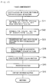
- Fig. 10 is a flowchart showing details of the color change process.
- the coefficient operation unit 52 reads out a color E(Re,Ge,Be) of each pixel included in the color image stored in the original image memory 22, and substitutes the color E(Re,Ge,Be) into the right-hand side of Equation (5), thereby determining a coefficient matrix K(k1,k2,k3) corresponding to the color E(Re,Ge,Be).
- the coefficient matrix K(k1,k2,k3) is stored in the coefficient memory 28.
- the color change operation unit 54 executes the processing of steps S22 through S24.
- step S22 it is determined whether the coefficient k1 of the first color vector V1 is positive. The reason why the branching decision is based on the sign of the first coefficient k1 will be described later.
- step S23 which executes color change operation.
- the color change operation converts the color E(Re,Ge,Be) of the current pixel expressed by Equation (1) into another color E'(Re',Ge',Be') according to the following Equation (6):
- Equation (6) the first color vector V1 in the right-hand side of Equation (1) is replaced by a substitute color vector Vrep.
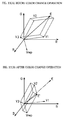
- Fig. 11 shows color vectors representing a color E prior to the color change operation and another color E' after the color change.
- the vector representing the color E prior to the color change operation is a composite vector composed of the first through the third color vectors V1, V2, V3 as shown in Fig. 11(A).
- the vector representing the color E' after the color change is a composite vector composed of the substitute color vector Vrep, the second color vector V2, and the third color vector V3 as shown in Fig. 11(B).
- the matrix operation unit 50 pre-computes a color change matrix Mrep expressed by Equation (7) given below, and stores the color change matrix Mrep into the matrix memory 26 at step S15 in the flowchart of Fig. 5:
- the color change matrix Mrep is obtained by replacing the first color vector V1 with the substitute color vector Vrep in the matrix M (expressed by Equation (3)), which consists of the first through third color vectors V1, V2, V3.
- the color E' after the color change is computed at step S23 by multiplying the coefficient matrix K determined according to Equation (5) by the color change matrix Mrep.
- Image data representing the color E' after the color change for each pixel are stored into the color-changed image memory 30.
- step S23 After the process of step S23 is completed or when the first coefficient k1 is not positive at step S22, the process proceeds to step S24 to determine whether there are any more pixels to be processed. If exists, the process returns to step S21 to repeat the processing of steps S21 through S23. If not, the process returns to the main routine shown in Fig. 3.
- the reason why the branching decision at step S22 is based on the sign of the first coefficient k1 is as follows.
- the first coefficient k1 represents the intensity of the first color vector V1, among the three vectors V1-V3, in the color of each pixel.
- the more the color of the current pixel contains a component of the first color vector V1 (that is, the component of the subject color) the greater the first coefficient k1 becomes. Therefore the execution of the color change operation only if the first coefficient k1 is positive can change only the color of those pixels which contain a component of the subject color.
- the hatched section represents a target hue range which is subjected to the color change operation.
- the coefficient k1 for the first color vector V1 (that is, the subject color vector) is positive.
- the target hue range of the color change operation is one of the two semicircular hue ranges separated by the non-subject color vector V2 (more precisely, the hue component of the vector V2) and its anti-parallel vector -V2, and includes the subject color vector V1 (more precisely, the hue component of the vector V1).
- the execution of the color change operation only for the color of pixels with the positive first coefficient k1 has other advantages. As the value of the first coefficient k1 increases, the color E' after the color change (expressed by Equation (6)) becomes closer to the substitute color. In the image part with a smooth color gradient, this allows the subject color component to be replaced by the substitute color component while maintaining the smooth color gradient.
- step S6 the image obtained through the color change operation is displayed on the color CRT 38.
- Fig. 12 is a flowchart showing a routine of color change process executed in a second embodiment of the present invention.
- the flowchart of Fig. 12 is similar to that of Fig. 10, except that step S22 in Fig. 10 is replaced by step S30.
- step S30 only if both the first coefficient k1 and the second coefficient k2 are positive, the process proceeds to step S23 to execute the color change operation.
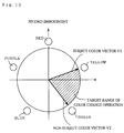
- Fig. 13 shows a target hue range which is subjected to the color change operation in the second embodiment.
- the hatched section in Fig. 13 shows the target hue range of the color change operation.
- the first coefficient k1 and the second coefficient k2 are positive in the target hue range.
- the target hue range of the color change operation in the second embodiment is an area defined by the subject color vector (first color vector) V1 and the non-subject color vector (second color vector) V2.
- the user can specify the borders of the target hue range of the color change operation by the subject color and the non-subject color.
- the user can easily and accurately determine the desired hue range as a target of the color change operation by specifying the subject color and the non-subject color.
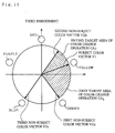
- a plurality of non-subject colors are specified at step S2 in the flowchart of Fig. 3.
- Fig. 14 shows three non-subject color vectors V2a through V2c corresponding to three non-subject colors on the hue ring.
- Fig. 15 is a flowchart showing details of step S4 (in the flowchart of Fig. 3) executed in the third embodiment.
- step S13 one subject color vector (first color vector) and a plurality of non-subject color vectors (second color vectors) are transformed to vectors in the HSV coordinate system.
- two non-subject color vectors which have the smallest angle not greater than 180 degrees and which include the subject color vector V1 within the angle are extracted as a "pair of adjoining non-subject color vectors".
- the first non-subject color vector V2a and the second non-subject color vector V2b are chosen as the pair of adjoining non-subject color vectors.
- the plurality of non-subject colors specified first in the third embodiment correspond to a plurality of candidate colors in the present invention.
- Equations (8a) and (8b) and color change matrices Mrepa and Mrepb expressed by Equations (9a) and (9b) are prepared for the pair of adjoining non-subject color vectors V2a and V2b:
- the matrices Ma and Mb given by Equations (8a) and (8b) are hereinafter referred to as "color coordinate matrices".
- the process proceeds to step S16 at which inverses of the color coordinate matrices Ma and Mb are prepared respectively.
- the two color coordinate matrices Ma and Mb correspond to "two sets of vector combinations" in the present invention.
- the matrix Ma including the selected non-subject color vector V2a and its inverse matrix are prepared at steps S15 and S16.
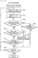
- Fig. 16 is a flowchart showing a routine of the color change process executed in the third embodiment.
- step S40 any one of the color coordinate matrices prepared at step S15 is selected.
- step S41 at which an inverse of the selected color coordinate matrix is computed, and a coefficient matrix for one target pixel is calculated from the inverse matrix according to Equations (10a)-(10b):
- a first coefficient matrix ka is calculated according to Equation (10a) at step S41.
- step S42 it is determined whether only one color coordinate matrix or two color coordinate matrices are prepared at step S15 in the flowchart of Fig. 15.
- the pair of adjoining non-subject color vectors V2a and V2b are extracted as in the example of Fig. 14, it is determined at step S42 that two color coordinate matrices Ma and Mb have been prepared at step S15 and the process proceeds to step S43.
- step S43 only if both the first and the second coefficients (for example, k1a and k2a) included in the coefficient matrix (for example, Ka) computed at step S41 are positive, the process proceeds to step S45 to execute the color change operation.
- the target hue range of the color change operation is a first target area CA1 shown in Fig. 14.
- the first target area CA1 is defined by the first non-subject color vector V2a and the subject color vector V1.
- step S43 in the flowchart of Fig. 16 if at least one of the first and second coefficients included in the coefficient matrix is not positive, the process proceeds to step S46, at which it is determined whether there remains another color coordinate matrix to be processed. If the answer is positive at step S46, the process returns to step S40 to select a next color coordinate matrix (for example, the second color coordinate matrix Mb) and repeats the processing of steps S41 through S46. If the color coordinate matrix Mb corresponding to the second non-subject color vector V2b is selected at step S40, the target hue range of the color change operation is a second target area CA2 shown in Fig. 14. The second target area CA2 is defined by the second non-subject color vector V2b and the subject color vector V1.
- the hue range defined by the two non-subject color vectors V2a and V2b represents the target color range which is subjected to the color change operation.
- the user can thus specify the borders of the target hue range of the color change operation by the two non-subject colors V2a and V2b.
- either one of the first color coordinate matrix Ma or the second color coordinate matrix Mb is selected according to the signs of the first and second coefficients included in the coefficient matrix, which is successively computed for the selected color coordinate matrix. This simplifies the process of the color change operation.
- step S47 it is determined whether there are any more target pixels to be processed by the color change operation. If any non-processed target pixel exists, the process returns to step S40 to repeat the processing of steps S40 through S46. If there are no more pixels at step S47, the process returns to the main routine.
- step S18 If only one non-subject color vector is selected at step S18 in the flowchart of Fig. 18, only one color coordinate matrix is prepared at step S15, and therefore the process proceeds from step S42 to step S44 in the flowchart of Fig. 16.
- step S44 it is determined whether to execute the color change operation on the basis of the sign of the first coefficient k1 at step S45. This flow is identical with that of the first embodiment. Alternatively, as is the case in the second embodiment, the color change operation can be executed only if both the first and second coefficients included in the coefficient matrix are positive.
- the target hue range of the color change operation is an area defined by the two non-subject colors in the third embodiment, the user can thus easily and accurately set the desired hue range as a target of the color change operation.
- One applicable method comprises the steps of: projecting the subject color vector V1, the pair of adjoining non-subject color vectors V2a and V2b, and a vector VP of a target pixel color onto the hue ring plane; computing cross products of the target pixel-color vector VP and the other color vectors; and selecting the color coordinate matrix based on the signs of the cross-product vectors.
- the vector VP of the target pixel color is within a first area defined by the subject color vector V1 and the adjoining non-subject color vector V2a, based on the sign of the cross product of the subject color vector V1 and the target pixel vector VP as well as the sign of the cross product of the target pixel vector VP and the adjoining non-subject color vector V2a. If the vector VP of the target pixel color is determined to be within the first area, the first color coordinate matrix Ma is selected.
- the vector VP of the target pixel color is within a second area defined by the subject color vector V1 and the adjoining non-subject color vector V2b, based on the sign of a cross product of the subject color vector V1 and the target pixel vector VP as well as the sign of a cross product of the target pixel vector VP and the adjoining non-subject color vector V2b. If the vector VP of the target pixel color is determined to be within the second area, the second color coordinate matrix Mb is selected.
- Another applicable method comprises the steps of: projecting the subject color vector V1, the pair of adjoining non-subject color vectors V2a and V2b, and the vector VP of a target pixel color onto the hue ring plane; computing hue angles of two specified vectors; and selecting a color coordinate matrix based on the hue angles. For example, a hue angle ⁇ 1 between the vectors V2a and V1 is computed, and so are another hue angle ⁇ P between the vectors V2a and VP, and still another hue angel ⁇ 2 between the vectors V2a and V2. If ⁇ P ⁇ 1 ⁇ 2 holds, the first color coordinate matrix Ma will be selected. If ⁇ 1 ⁇ P ⁇ 2 holds, on the other hand, the second color coordinate matrix Mb will be selected.
- the color E' after the color change (that is, Ea' or Eb') is determined by the color change matrix M repa or M repb corresponding to the selected color coordinate matrix Ma or Mb.
Landscapes
- Physics & Mathematics (AREA)
- General Physics & Mathematics (AREA)
- Engineering & Computer Science (AREA)
- Theoretical Computer Science (AREA)
- Color Image Communication Systems (AREA)
- Image Processing (AREA)
- Processing Or Creating Images (AREA)
- Editing Of Facsimile Originals (AREA)
- Facsimile Image Signal Circuits (AREA)
Applications Claiming Priority (2)
| Application Number | Priority Date | Filing Date | Title |
|---|---|---|---|
| JP97830/95 | 1995-03-29 | ||
| JP09783095A JP3400888B2 (ja) | 1995-03-29 | 1995-03-29 | カラー画像の色変更方法 |
Publications (2)
| Publication Number | Publication Date |
|---|---|
| EP0735511A2 true EP0735511A2 (de) | 1996-10-02 |
| EP0735511A3 EP0735511A3 (de) | 1997-05-14 |
Family
ID=14202644
Family Applications (1)
| Application Number | Title | Priority Date | Filing Date |
|---|---|---|---|
| EP96103981A Withdrawn EP0735511A3 (de) | 1995-03-29 | 1996-03-13 | Verfahren und Vorrichtung zum Ändern einer bestimmten Farbe in einem Farbbilde |
Country Status (3)
| Country | Link |
|---|---|
| US (1) | US5719639A (de) |
| EP (1) | EP0735511A3 (de) |
| JP (1) | JP3400888B2 (de) |
Cited By (5)
| Publication number | Priority date | Publication date | Assignee | Title |
|---|---|---|---|---|
| WO1998011510A1 (en) * | 1996-09-12 | 1998-03-19 | Discreet Logic Inc. | Processing image data |
| FR2803419A1 (fr) * | 1999-12-31 | 2001-07-06 | Vision Ere | Procede de colorisation d'une image ou d'une matrice d'images sur un ecran connecte a un systeme inter-reseaux |
| US6456300B1 (en) | 1999-03-31 | 2002-09-24 | Autodesk Canada Inc. | Method and apparatus for processing image data to produce control data |
| US6496599B1 (en) | 1998-04-01 | 2002-12-17 | Autodesk Canada Inc. | Facilitating the compositing of video images |
| US6571012B1 (en) | 1998-04-01 | 2003-05-27 | Autodesk Canada Inc. | Adjusting a softness region |
Families Citing this family (56)
| Publication number | Priority date | Publication date | Assignee | Title |
|---|---|---|---|---|
| JPH09114432A (ja) * | 1995-10-20 | 1997-05-02 | Brother Ind Ltd | 色変換装置 |
| JPH09179539A (ja) * | 1995-12-27 | 1997-07-11 | Brother Ind Ltd | 色調整装置 |
| JP3456818B2 (ja) * | 1996-03-04 | 2003-10-14 | 株式会社日立国際電気 | 色調補正装置 |
| JP3750830B2 (ja) * | 1996-08-30 | 2006-03-01 | ソニー株式会社 | 撮像装置における色補正装置 |
| US7630006B2 (en) | 1997-10-09 | 2009-12-08 | Fotonation Ireland Limited | Detecting red eye filter and apparatus using meta-data |
| US7042505B1 (en) | 1997-10-09 | 2006-05-09 | Fotonation Ireland Ltd. | Red-eye filter method and apparatus |
| US7738015B2 (en) | 1997-10-09 | 2010-06-15 | Fotonation Vision Limited | Red-eye filter method and apparatus |
| US7123277B2 (en) * | 2001-05-09 | 2006-10-17 | Clairvoyante, Inc. | Conversion of a sub-pixel format data to another sub-pixel data format |
| US7307646B2 (en) * | 2001-05-09 | 2007-12-11 | Clairvoyante, Inc | Color display pixel arrangements and addressing means |
| US7167186B2 (en) * | 2003-03-04 | 2007-01-23 | Clairvoyante, Inc | Systems and methods for motion adaptive filtering |
| US20040196302A1 (en) | 2003-03-04 | 2004-10-07 | Im Moon Hwan | Systems and methods for temporal subpixel rendering of image data |
| US20040233308A1 (en) * | 2003-05-20 | 2004-11-25 | Elliott Candice Hellen Brown | Image capture device and camera |
| US7268748B2 (en) * | 2003-05-20 | 2007-09-11 | Clairvoyante, Inc | Subpixel rendering for cathode ray tube devices |
| US7230584B2 (en) * | 2003-05-20 | 2007-06-12 | Clairvoyante, Inc | Projector systems with reduced flicker |
| US7970182B2 (en) | 2005-11-18 | 2011-06-28 | Tessera Technologies Ireland Limited | Two stage detection for photographic eye artifacts |
| US7574016B2 (en) * | 2003-06-26 | 2009-08-11 | Fotonation Vision Limited | Digital image processing using face detection information |
| US8170294B2 (en) * | 2006-11-10 | 2012-05-01 | DigitalOptics Corporation Europe Limited | Method of detecting redeye in a digital image |
| US8254674B2 (en) * | 2004-10-28 | 2012-08-28 | DigitalOptics Corporation Europe Limited | Analyzing partial face regions for red-eye detection in acquired digital images |
| US7689009B2 (en) * | 2005-11-18 | 2010-03-30 | Fotonation Vision Ltd. | Two stage detection for photographic eye artifacts |
| US8036458B2 (en) * | 2007-11-08 | 2011-10-11 | DigitalOptics Corporation Europe Limited | Detecting redeye defects in digital images |
| US7920723B2 (en) * | 2005-11-18 | 2011-04-05 | Tessera Technologies Ireland Limited | Two stage detection for photographic eye artifacts |
| US7616233B2 (en) * | 2003-06-26 | 2009-11-10 | Fotonation Vision Limited | Perfecting of digital image capture parameters within acquisition devices using face detection |
| US7792970B2 (en) * | 2005-06-17 | 2010-09-07 | Fotonation Vision Limited | Method for establishing a paired connection between media devices |
| US20050140801A1 (en) * | 2003-08-05 | 2005-06-30 | Yury Prilutsky | Optimized performance and performance for red-eye filter method and apparatus |
| US8520093B2 (en) * | 2003-08-05 | 2013-08-27 | DigitalOptics Corporation Europe Limited | Face tracker and partial face tracker for red-eye filter method and apparatus |
| US9412007B2 (en) * | 2003-08-05 | 2016-08-09 | Fotonation Limited | Partial face detector red-eye filter method and apparatus |
| JP4141923B2 (ja) * | 2003-09-18 | 2008-08-27 | 村田機械株式会社 | カラー画像処理装置 |
| US6980219B2 (en) * | 2003-10-21 | 2005-12-27 | Clairvoyante, Inc | Hue angle calculation system and methods |
| US7598961B2 (en) * | 2003-10-21 | 2009-10-06 | Samsung Electronics Co., Ltd. | method and apparatus for converting from a source color space to a target color space |
| US7176935B2 (en) * | 2003-10-21 | 2007-02-13 | Clairvoyante, Inc. | Gamut conversion system and methods |
| US20110102643A1 (en) * | 2004-02-04 | 2011-05-05 | Tessera Technologies Ireland Limited | Partial Face Detector Red-Eye Filter Method and Apparatus |
| US7619637B2 (en) * | 2004-04-09 | 2009-11-17 | Samsung Electronics Co., Ltd. | Systems and methods for improved gamut mapping from one image data set to another |
| US7301543B2 (en) * | 2004-04-09 | 2007-11-27 | Clairvoyante, Inc. | Systems and methods for selecting a white point for image displays |
| JP4539964B2 (ja) * | 2004-07-21 | 2010-09-08 | 大日本スクリーン製造株式会社 | 画像の領域分割 |
| CN1882103B (zh) * | 2005-04-04 | 2010-06-23 | 三星电子株式会社 | 实现改进的色域对映演算的系统及方法 |
| US7599577B2 (en) * | 2005-11-18 | 2009-10-06 | Fotonation Vision Limited | Method and apparatus of correcting hybrid flash artifacts in digital images |
| EP1987475A4 (de) | 2006-02-14 | 2009-04-22 | Fotonation Vision Ltd | Automatische erkennung und korrektur von fehlern des blitzes mit rote-augen-effekt |
| US7592996B2 (en) * | 2006-06-02 | 2009-09-22 | Samsung Electronics Co., Ltd. | Multiprimary color display with dynamic gamut mapping |
| US7965875B2 (en) * | 2006-06-12 | 2011-06-21 | Tessera Technologies Ireland Limited | Advances in extending the AAM techniques from grayscale to color images |
| JP4791900B2 (ja) * | 2006-07-10 | 2011-10-12 | 北海道公立大学法人 札幌医科大学 | 画像処理装置および画像処理プログラム |
| US8406514B2 (en) * | 2006-07-10 | 2013-03-26 | Nikon Corporation | Image processing device and recording medium storing image processing program |
| US8259127B2 (en) * | 2006-09-30 | 2012-09-04 | Samsung Electronics Co., Ltd. | Systems and methods for reducing desaturation of images rendered on high brightness displays |
| US8086029B1 (en) | 2006-12-13 | 2011-12-27 | Adobe Systems Incorporated | Automatic image adjustment |
| US7920739B2 (en) * | 2006-12-13 | 2011-04-05 | Adobe Systems Incorporated | Automatically selected adjusters |
| US8055067B2 (en) * | 2007-01-18 | 2011-11-08 | DigitalOptics Corporation Europe Limited | Color segmentation |
| US7995804B2 (en) * | 2007-03-05 | 2011-08-09 | Tessera Technologies Ireland Limited | Red eye false positive filtering using face location and orientation |
| US8503818B2 (en) | 2007-09-25 | 2013-08-06 | DigitalOptics Corporation Europe Limited | Eye defect detection in international standards organization images |
| CN101828202A (zh) * | 2007-10-17 | 2010-09-08 | 三菱电机株式会社 | 图像处理装置 |
| US8212864B2 (en) * | 2008-01-30 | 2012-07-03 | DigitalOptics Corporation Europe Limited | Methods and apparatuses for using image acquisition data to detect and correct image defects |
| US8081254B2 (en) * | 2008-08-14 | 2011-12-20 | DigitalOptics Corporation Europe Limited | In-camera based method of detecting defect eye with high accuracy |
| US8218860B1 (en) | 2008-08-28 | 2012-07-10 | Adobe Systems Incorporated | Method and system for replacing color ranges in an image |
| JP2010154009A (ja) * | 2008-12-24 | 2010-07-08 | Brother Ind Ltd | 画像処理装置と画像処理プログラム |
| US8428351B2 (en) * | 2008-12-24 | 2013-04-23 | Brother Kogyo Kabushiki Kaisha | Image processing device |
| US8373883B2 (en) * | 2009-09-30 | 2013-02-12 | Hewlett-Packard Development Company, L.P. | System and method for managing resource consumption during print production |
| JP2011237907A (ja) * | 2010-05-07 | 2011-11-24 | Sony Corp | 画像処理装置、画像処理方法、およびプログラム |
| EP2797326A1 (de) * | 2013-04-22 | 2014-10-29 | Nederlandse Organisatie voor toegepast -natuurwetenschappelijk onderzoek TNO | Bildfarbkorrektur |
Family Cites Families (9)
| Publication number | Priority date | Publication date | Assignee | Title |
|---|---|---|---|---|
| US4862251A (en) * | 1984-04-09 | 1989-08-29 | Corporate Communications Consultants, Inc. | Color correction system and method |
| US4710800A (en) * | 1984-04-27 | 1987-12-01 | Utah Scientific Advanced Development Center, Inc. | Apparatus for allowing operator selection of a color region of a video image for receiving color corrections |
| US4953008A (en) * | 1986-09-08 | 1990-08-28 | Encore Video, Inc. | Method and apparatus for uniform saturation, hue and luminance correction |
| US5521615A (en) * | 1989-05-08 | 1996-05-28 | Hewlett-Packard Company | Display system for instruments |
| GB9002477D0 (en) * | 1990-02-05 | 1990-04-04 | Crosfield Electronics Ltd | Improvements relating to control data arrays |
| JPH0540833A (ja) * | 1991-08-05 | 1993-02-19 | Fujitsu Ltd | カラ−画像制御方法 |
| FR2681967B1 (fr) * | 1991-10-01 | 1994-11-25 | Electronics For Imaging Inc | Procede et appareil pour modifier les couleurs d'une image a l'aide d'un ordinateur. |
| US5487020A (en) * | 1993-01-18 | 1996-01-23 | Canon Information Systems Research Australia Pty Ltd. | Refinement of color images using reference colors |
| EP0693738A3 (de) * | 1994-06-23 | 1996-11-06 | Dainippon Screen Mfg | Verfahren und Vorrichtung zur Erzeugung farbiger Masken |
-
1995
- 1995-03-29 JP JP09783095A patent/JP3400888B2/ja not_active Expired - Fee Related
-
1996
- 1996-03-13 EP EP96103981A patent/EP0735511A3/de not_active Withdrawn
- 1996-03-20 US US08/619,887 patent/US5719639A/en not_active Expired - Lifetime
Cited By (7)
| Publication number | Priority date | Publication date | Assignee | Title |
|---|---|---|---|---|
| WO1998011510A1 (en) * | 1996-09-12 | 1998-03-19 | Discreet Logic Inc. | Processing image data |
| US6445816B1 (en) | 1996-09-12 | 2002-09-03 | Autodesk Canada Inc. | Compositing video image data |
| US6496599B1 (en) | 1998-04-01 | 2002-12-17 | Autodesk Canada Inc. | Facilitating the compositing of video images |
| US6571012B1 (en) | 1998-04-01 | 2003-05-27 | Autodesk Canada Inc. | Adjusting a softness region |
| US6456300B1 (en) | 1999-03-31 | 2002-09-24 | Autodesk Canada Inc. | Method and apparatus for processing image data to produce control data |
| FR2803419A1 (fr) * | 1999-12-31 | 2001-07-06 | Vision Ere | Procede de colorisation d'une image ou d'une matrice d'images sur un ecran connecte a un systeme inter-reseaux |
| WO2001050421A1 (fr) * | 1999-12-31 | 2001-07-12 | Societe Vision'ere | Procede de colorisation d'une image ou d'une matrice d'images sur un ecran connecte a un systeme inter-reseaux |
Also Published As
| Publication number | Publication date |
|---|---|
| US5719639A (en) | 1998-02-17 |
| EP0735511A3 (de) | 1997-05-14 |
| JP3400888B2 (ja) | 2003-04-28 |
| JPH08272942A (ja) | 1996-10-18 |
Similar Documents
| Publication | Publication Date | Title |
|---|---|---|
| EP0735511A2 (de) | Verfahren und Vorrichtung zum Ändern einer bestimmten Farbe in einem Farbbilde | |
| EP0693738A2 (de) | Verfahren und Vorrichtung zur Erzeugung farbiger Masken | |
| US5202935A (en) | Color conversion apparatus for altering color values within selected regions of a reproduced picture | |
| US6021221A (en) | Image processing apparatus | |
| DE4418782C2 (de) | System und Verfahren zum Einstellen eines Farbbildes | |
| US5844542A (en) | Image processing apparatus and method with multi-dimensional display of image adjustment levels | |
| JP4452498B2 (ja) | リアルタイムデジタルビデオ画像において個々の色の色相又は彩度を独立して制御するための方法 | |
| US5563720A (en) | Expert system for image enhancement | |
| PT947955E (pt) | Aparelho para gerar curvas gama adaptadas a uma aplicacao determinada para um equipamento de correccao da cor | |
| JPH08186727A (ja) | 画像処理装置及び方法 | |
| US6081796A (en) | Proportion predicting system and method of making mixture | |
| US7671871B2 (en) | Graphical user interface for color correction using curves | |
| EP0481525B1 (de) | Farbwandlungsvorrichtung zur Änderung von Farbwerten innerhalb ausgewählter Flächen eines Wiedergabebildes | |
| US6075885A (en) | Method of and apparatus for extracting cross plane area of gamut and computer program product for carrying out the extraction | |
| US5602972A (en) | Pixel and data format conversion processor for gravure | |
| JPH08123940A (ja) | 画像領域抽出装置及びその画像領域抽出方法 | |
| CN109003242B (zh) | 一种图像增强处理方法及装置 | |
| JP3930343B2 (ja) | 均等色空間構成処理方法、処理装置、この処理方法を実行する処理プログラムおよび当該処理プログラムを記録した記録媒体 | |
| JPH03121571A (ja) | カラー画像処理装置 | |
| JP2896311B2 (ja) | カラー画像のマスク作成方法 | |
| JP3847397B2 (ja) | 色調修正方法 | |
| JP2896319B2 (ja) | カラー画像のマスク作成方法 | |
| JP2896317B2 (ja) | カラー画像のマスク作成方法 | |
| JP2896320B2 (ja) | カラー画像のマスク作成方法 | |
| US20250315928A1 (en) | Iqv metric for ‘false color’ artifacts in chromatic areas |
Legal Events
| Date | Code | Title | Description |
|---|---|---|---|
| PUAI | Public reference made under article 153(3) epc to a published international application that has entered the european phase |
Free format text: ORIGINAL CODE: 0009012 |
|
| AK | Designated contracting states |
Kind code of ref document: A2 Designated state(s): DE FR GB |
|
| PUAL | Search report despatched |
Free format text: ORIGINAL CODE: 0009013 |
|
| AK | Designated contracting states |
Kind code of ref document: A3 Designated state(s): DE FR GB |
|
| 17P | Request for examination filed |
Effective date: 19970821 |
|
| 17Q | First examination report despatched |
Effective date: 20000309 |
|
| STAA | Information on the status of an ep patent application or granted ep patent |
Free format text: STATUS: THE APPLICATION IS DEEMED TO BE WITHDRAWN |
|
| 18D | Application deemed to be withdrawn |
Effective date: 20000720 |