EP0735552A1 - Transformateur à haute tension pour un récepteur de télévision - Google Patents
Transformateur à haute tension pour un récepteur de télévision Download PDFInfo
- Publication number
- EP0735552A1 EP0735552A1 EP96104221A EP96104221A EP0735552A1 EP 0735552 A1 EP0735552 A1 EP 0735552A1 EP 96104221 A EP96104221 A EP 96104221A EP 96104221 A EP96104221 A EP 96104221A EP 0735552 A1 EP0735552 A1 EP 0735552A1
- Authority
- EP
- European Patent Office
- Prior art keywords
- winding
- voltage
- distance
- partial
- chambers
- Prior art date
- Legal status (The legal status is an assumption and is not a legal conclusion. Google has not performed a legal analysis and makes no representation as to the accuracy of the status listed.)
- Granted
Links
- 238000004804 winding Methods 0.000 claims abstract description 68
- 230000010355 oscillation Effects 0.000 claims abstract 2
- 239000003990 capacitor Substances 0.000 description 7
- 230000008878 coupling Effects 0.000 description 3
- 238000010168 coupling process Methods 0.000 description 3
- 238000005859 coupling reaction Methods 0.000 description 3
- 230000000712 assembly Effects 0.000 description 1
- 238000000429 assembly Methods 0.000 description 1
- 239000011248 coating agent Substances 0.000 description 1
- 238000000576 coating method Methods 0.000 description 1
- 238000010276 construction Methods 0.000 description 1
- 238000013016 damping Methods 0.000 description 1
- 230000006866 deterioration Effects 0.000 description 1
- 238000010586 diagram Methods 0.000 description 1
- 230000000694 effects Effects 0.000 description 1
- 230000002349 favourable effect Effects 0.000 description 1
- 230000002452 interceptive effect Effects 0.000 description 1
- 230000007704 transition Effects 0.000 description 1
- 230000001960 triggered effect Effects 0.000 description 1
Images
Classifications
-
- H—ELECTRICITY
- H02—GENERATION; CONVERSION OR DISTRIBUTION OF ELECTRIC POWER
- H02M—APPARATUS FOR CONVERSION BETWEEN AC AND AC, BETWEEN AC AND DC, OR BETWEEN DC AND DC, AND FOR USE WITH MAINS OR SIMILAR POWER SUPPLY SYSTEMS; CONVERSION OF DC OR AC INPUT POWER INTO SURGE OUTPUT POWER; CONTROL OR REGULATION THEREOF
- H02M7/00—Conversion of AC power input into DC power output; Conversion of DC power input into AC power output
- H02M7/02—Conversion of AC power input into DC power output without possibility of reversal
- H02M7/04—Conversion of AC power input into DC power output without possibility of reversal by static converters
- H02M7/06—Conversion of AC power input into DC power output without possibility of reversal by static converters using discharge tubes without control electrode or semiconductor devices without control electrode
- H02M7/10—Conversion of AC power input into DC power output without possibility of reversal by static converters using discharge tubes without control electrode or semiconductor devices without control electrode arranged for operation in series, e.g. for multiplication of voltage
-
- H—ELECTRICITY
- H01—ELECTRIC ELEMENTS
- H01F—MAGNETS; INDUCTANCES; TRANSFORMERS; SELECTION OF MATERIALS FOR THEIR MAGNETIC PROPERTIES
- H01F38/00—Adaptations of transformers or inductances for specific applications or functions
- H01F38/42—Flyback transformers
-
- H—ELECTRICITY
- H01—ELECTRIC ELEMENTS
- H01F—MAGNETS; INDUCTANCES; TRANSFORMERS; SELECTION OF MATERIALS FOR THEIR MAGNETIC PROPERTIES
- H01F5/00—Coils
- H01F5/02—Coils wound on non-magnetic supports, e.g. formers
- H01F2005/022—Coils wound on non-magnetic supports, e.g. formers wound on formers with several winding chambers separated by flanges, e.g. for high voltage applications
Definitions
- the invention is based on a high-voltage transformer according to the preamble of claim 1.
- the charging capacitor for the high voltage is only recharged on the high-voltage winding during the relatively narrow peak of the flyback pulse.
- This narrow pulse peak results in a relatively large internal resistance for the high voltage source.
- an odd harmonic such as e.g. the 5th, the 9th, the 13th harmonic.
- the aforementioned system which is tuned to a frequency, is suddenly triggered to vibrate.
- the image is controlled so brightly for a few msec for the viewer that a beam current of the order of 3 to 5 mA flows.
- the generally provided regulation and limitation of the beam current does not start because this control circuit must have a time constant of approximately 10 to 15 ms so that real white areas in the image are not falsified.
- With such a High beam current generally produces the highest overshoot in the high voltage winding when the high voltage rectifiers are switched off.
- the return pulse peak on the primary winding on the switching transistor can increase by more than 150 V.
- the invention has for its object to design the transformer so that the amplitude of the overshoot in the high-voltage winding is significantly reduced.
- the number of partial windings of the high-voltage winding is greater than the number of diodes, and separate partial windings are tuned to different harmonics.
- the invention thus turns away from the prior art, in which a harmonization has been carried out as far as possible.
- the bandwidth of the vibration system is increased in the sense of a bandpass filter characteristic, so that the damping is increased and the quality is reduced.
- the required precision in tuning is considerably reduced.
- the adjustment to different harmonics changes the form of the return pulse on the high-voltage winding in such a way that the pulse on the primary winding and thus on the switching transistor remains largely free of disturbing and dangerous voltage increases. This will endanger the switching transistor considerably reduced by such voltage increases.
- the shape of the return pulse at the high-voltage winding also reduces the internal resistance of the high-voltage source. In addition, the internal resistance is largely independent of tolerances.
- the above-mentioned LRC circuit previously provided in the primary path and used to suppress voltage increases, is no longer required. Interfering influences of the high-voltage transformer are also considerably reduced by control on neighboring assemblies, such as the video amplifier.
- Four partial windings are preferably tuned to four different harmonics, in particular to the 7th, the 8.5th, the 9.5th and 11th harmonic of the frequency of the return vibration. This coordination results in a return pulse with a particularly favorable course.
- the partial windings of the high-voltage winding are preferably in chambers of a chamber bobbin.
- the matching to the desired harmonic can be achieved by the distance of the chamber base from the core, by the distance of the chambers from each other and / or by the degree of filling of the chambers with the partial winding.
- Such a chamber bobbin offers several options in its dimensioning to achieve the desired tuning.
- the distance between the first and second and between the penultimate and last chamber of the chamber bobbin can be significantly smaller than the distance between the other chambers. This reduced distance reduces the winding capacity between the windings and thus makes it easier to tune to a particularly low harmonic.
- the significantly smaller distance between the chambers at the ends of the coil body is approximately 30-50% of the distance between the other chambers.
- the first partial winding and the last partial winding then generally have a much lower coupling than the partial windings in the central region of the chamber coil former, which makes it easier to tune to the harmonic desired in each case.
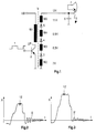
- the high-voltage winding is constructed according to the diode split principle in that high-voltage rectifier diodes 3, 4, 5 lie between the partial windings W2, W3, W4, W5.
- the secondary side therefore begins with one winding and ends with one winding. This means that there is no longer a diode between the winding W2 and earth and the winding W5 and the high-voltage connection.
- the number of partial windings W2-W5 is thus four, which is greater than the number of three diodes 3, 4, 5 between them.
- the high-voltage winding supplies the high voltage UH to the charging capacitor 6 essentially formed by the anode coating of the picture tube 7.
- the partial winding W2 is approximately on the 7th harmonic, the partial winding W3 on the 8.5. Harmonics, the partial winding W4 to the 9.5. Harmonics and the partial winding W5 tuned to the 11th harmonic. The windings W3 and W4 together result in a tuning to the 9th harmonic.
- Fig. 3 shows the return pulse on the high voltage winding in the tuning described.
- the pulse according to Fig. 3 compared to the pulse.
- Fig. 2 several advantages.
- the amplitude of the return pulse which is decisive for the size of the high voltage that can be achieved, is greater.
- the undesired saddling 12 ′ at the pulse tip is also significantly less, which is advantageous for the internal resistance.
- the pulse peak is wider, so that the charging time for the charging capacitor is increased and thus the internal resistance is reduced.
- Another advantage is that at the end of the pulse there is no such high overshoot according to FIG. 2 on a singular frequency, but only an overshoot with reduced amplitude and reduced duration occurs due to interference between the different frequencies that are effective in the tuning.
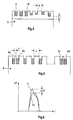
- Fig. 4 shows in principle a chamber bobbin 9.
- the partial windings W of the high-voltage winding are located in chambers 8 of the chamber bobbin 9.
- the desired tuning to a particular harmonic can be achieved by various design parameters of the chamber bobbin 9. These are in particular the different filling of the chambers 8 shown with a partial winding W, the different spacing a of the chambers from one another due to different thickness of the chamber walls and a different thickness b of the slot base, that is to say the distance of the respective partial winding W from the core carrying the bobbin 9. For example, increasing the distance b reduces the coupling to achieve a certain tuning.
- FIG. 5 shows a further embodiment of the chamber bobbin 9.
- the distance c between the first chamber 8a and the second chamber 8b and the distance between the penultimate chamber 8c and the last chamber 8d are significantly smaller than the distance a between the chambers in the central region of the Chamber bobbin 9.
- the desired tuning to a desired harmonic can be achieved.
- the larger coupling capacitance between the chambers 8a and 8b and 8c and 8d enables tuning to particularly low harmonics due to the reduced distance c.
- the distance c is about 30% - 50% of the distance a.
Landscapes
- Engineering & Computer Science (AREA)
- Power Engineering (AREA)
- Details Of Television Scanning (AREA)
- Coils Or Transformers For Communication (AREA)
Applications Claiming Priority (2)
| Application Number | Priority Date | Filing Date | Title |
|---|---|---|---|
| DE19510678 | 1995-03-27 | ||
| DE19510678A DE19510678A1 (de) | 1995-03-27 | 1995-03-27 | Hochspannungstransformator für einen Fernsehempfänger |
Publications (2)
| Publication Number | Publication Date |
|---|---|
| EP0735552A1 true EP0735552A1 (fr) | 1996-10-02 |
| EP0735552B1 EP0735552B1 (fr) | 1998-11-18 |
Family
ID=7757533
Family Applications (1)
| Application Number | Title | Priority Date | Filing Date |
|---|---|---|---|
| EP96104221A Expired - Lifetime EP0735552B1 (fr) | 1995-03-27 | 1996-03-16 | Transformateur à haute tension pour un récepteur de télévision |
Country Status (5)
| Country | Link |
|---|---|
| US (1) | US5844793A (fr) |
| EP (1) | EP0735552B1 (fr) |
| JP (1) | JPH08273955A (fr) |
| CN (1) | CN1090866C (fr) |
| DE (2) | DE19510678A1 (fr) |
Cited By (2)
| Publication number | Priority date | Publication date | Assignee | Title |
|---|---|---|---|---|
| DE19900111A1 (de) * | 1999-01-05 | 2000-07-06 | Thomson Brandt Gmbh | Diodensplitt-Hochspannungstransformator |
| EP3131101A1 (fr) * | 2015-08-12 | 2017-02-15 | Mahle International GmbH | Corps de bobine pour une bobine électrique, bobine électrique comprenant un tel corps de bobine |
Families Citing this family (4)
| Publication number | Priority date | Publication date | Assignee | Title |
|---|---|---|---|---|
| TW369654B (en) * | 1997-07-07 | 1999-09-11 | Thomson Brandt Gmbh | Diode-split high-voltage transformer |
| CN1161970C (zh) * | 1998-04-09 | 2004-08-11 | 皇家菲利浦电子有限公司 | 高电压变压器 |
| US8553841B2 (en) * | 2010-07-26 | 2013-10-08 | X-Ray Optical Systems, Inc. | Compact, low noise power supply for advanced electronics applications, and X-ray analyzer applications thereof |
| US20130214607A1 (en) * | 2012-02-17 | 2013-08-22 | Enphase Energy, Inc. | Electromagnetic interference cancelling during power conversion |
Citations (6)
| Publication number | Priority date | Publication date | Assignee | Title |
|---|---|---|---|---|
| DE2504355A1 (de) * | 1974-02-04 | 1975-08-14 | Hitachi Ltd | Elektronenstrahlroehren-hochspannungsgenerator |
| EP0033450A1 (fr) * | 1980-01-21 | 1981-08-12 | Licentia Patent-Verwaltungs-GmbH | Transformateur de lignes pour récepteur de télévision |
| EP0082966A1 (fr) * | 1981-12-28 | 1983-07-06 | International Standard Electric Corporation | Tranformateur de lignes pour récepteurs de télévision |
| US4454572A (en) * | 1982-05-27 | 1984-06-12 | Zenith Radio Corporation | Flyback transformer with improved regulation |
| DE3602005A1 (de) * | 1985-01-23 | 1986-07-24 | Murata Manufacturing Co., Ltd., Nagaokakyo, Kyoto | Zeilentransformator |
| WO1992010906A1 (fr) * | 1990-12-10 | 1992-06-25 | Deutsche Thomson-Brandt Gmbh | Transformateur h.t. pour postes recepteurs de television |
Family Cites Families (11)
| Publication number | Priority date | Publication date | Assignee | Title |
|---|---|---|---|---|
| US3562623A (en) * | 1968-07-16 | 1971-02-09 | Hughes Aircraft Co | Circuit for reducing stray capacity effects in transformer windings |
| US3657632A (en) * | 1969-10-29 | 1972-04-18 | Matsushita Electric Industrial Co Ltd | Rectifying device |
| BE791522A (fr) * | 1971-11-18 | 1973-03-16 | Matsushita Electric Industrial Co Ltd | Transformateur haute tension associe a un circuit a diviation horizontale |
| GB1449646A (en) * | 1972-11-20 | 1976-09-15 | Matsushita Electric Industrial Co Ltd | High voltage generator for television apparatus |
| US3886434A (en) * | 1973-09-07 | 1975-05-27 | Warwick Electronics Inc | Flyback transformer |
| NL159223C (fr) * | 1973-10-10 | |||
| US3947749A (en) * | 1975-01-31 | 1976-03-30 | Hitachi, Ltd. | Apparatus for generating high voltage for cathode-ray tube |
| US5576681A (en) * | 1990-12-10 | 1996-11-19 | Deutsche Thomson-Brandt Gmbh | High voltage transformer |
| DE4101504A1 (de) * | 1991-01-19 | 1992-07-23 | Thomson Brandt Gmbh | Schaltung zur zeilenablenkung und hochspannungserzeugung in einem fernsehempfaenger |
| DE4129678A1 (de) * | 1991-09-06 | 1993-03-11 | Thomson Brandt Gmbh | Dioden-split-hochspannungstransformator fuer einen fernsehempfaenger |
| EP0585597B1 (fr) * | 1992-08-04 | 1999-05-12 | Deutsche Thomson-Brandt Gmbh | Transformateur de ligne à haute tension pour un récepteur de télévision |
-
1995
- 1995-03-27 DE DE19510678A patent/DE19510678A1/de not_active Withdrawn
-
1996
- 1996-03-11 US US08/613,422 patent/US5844793A/en not_active Expired - Fee Related
- 1996-03-16 DE DE59600825T patent/DE59600825D1/de not_active Expired - Fee Related
- 1996-03-16 EP EP96104221A patent/EP0735552B1/fr not_active Expired - Lifetime
- 1996-03-21 CN CN96103100A patent/CN1090866C/zh not_active Expired - Fee Related
- 1996-03-26 JP JP8070519A patent/JPH08273955A/ja active Pending
Patent Citations (6)
| Publication number | Priority date | Publication date | Assignee | Title |
|---|---|---|---|---|
| DE2504355A1 (de) * | 1974-02-04 | 1975-08-14 | Hitachi Ltd | Elektronenstrahlroehren-hochspannungsgenerator |
| EP0033450A1 (fr) * | 1980-01-21 | 1981-08-12 | Licentia Patent-Verwaltungs-GmbH | Transformateur de lignes pour récepteur de télévision |
| EP0082966A1 (fr) * | 1981-12-28 | 1983-07-06 | International Standard Electric Corporation | Tranformateur de lignes pour récepteurs de télévision |
| US4454572A (en) * | 1982-05-27 | 1984-06-12 | Zenith Radio Corporation | Flyback transformer with improved regulation |
| DE3602005A1 (de) * | 1985-01-23 | 1986-07-24 | Murata Manufacturing Co., Ltd., Nagaokakyo, Kyoto | Zeilentransformator |
| WO1992010906A1 (fr) * | 1990-12-10 | 1992-06-25 | Deutsche Thomson-Brandt Gmbh | Transformateur h.t. pour postes recepteurs de television |
Cited By (3)
| Publication number | Priority date | Publication date | Assignee | Title |
|---|---|---|---|---|
| DE19900111A1 (de) * | 1999-01-05 | 2000-07-06 | Thomson Brandt Gmbh | Diodensplitt-Hochspannungstransformator |
| US6459350B1 (en) | 1999-01-05 | 2002-10-01 | Thomson Licensing Sa | Diode-split high-voltage transformer |
| EP3131101A1 (fr) * | 2015-08-12 | 2017-02-15 | Mahle International GmbH | Corps de bobine pour une bobine électrique, bobine électrique comprenant un tel corps de bobine |
Also Published As
| Publication number | Publication date |
|---|---|
| EP0735552B1 (fr) | 1998-11-18 |
| JPH08273955A (ja) | 1996-10-18 |
| CN1090866C (zh) | 2002-09-11 |
| DE19510678A1 (de) | 1996-10-02 |
| US5844793A (en) | 1998-12-01 |
| DE59600825D1 (de) | 1998-12-24 |
| CN1140952A (zh) | 1997-01-22 |
Similar Documents
| Publication | Publication Date | Title |
|---|---|---|
| EP0028383B1 (fr) | Transformateur de balayage horizontal pour récepteur de télévision | |
| DE2841885C2 (de) | Zeilentransformator zur Verwendung in einer Horizontalablenkschaltung | |
| DE938851C (de) | Kathodenstrahlablenkeinrichtung mit Spartransformator | |
| DE1762629A1 (de) | Hochspannungs-Generatorschaltung | |
| DE4332714A1 (de) | Resonanzkreis | |
| DE2749847C2 (de) | Schaltnetzteil für einen Rundfunkempfänger, insbesondere einen Fernsehempfänger | |
| EP0735552B1 (fr) | Transformateur à haute tension pour un récepteur de télévision | |
| EP0585597B1 (fr) | Transformateur de ligne à haute tension pour un récepteur de télévision | |
| DE2504355B2 (de) | Elektronenstrahlröhren-Hochspannungsgenerator für Fernsehgeräte | |
| EP0729160B1 (fr) | Transformateur haute tension pour un récepteur de télévision | |
| EP0193057A2 (fr) | Transformateur pour récepteur de télévision | |
| DE2258132C2 (de) | Rücklaufhochspannungs- und Sägezahnstromgenerator | |
| DE2655466B2 (de) | Hochspannungsgenerator für Elektronenstrahlröhren, vorzugsweise für Fernsehempfänger und EDV-Sichtgeräte | |
| DE1537150A1 (de) | Schaltung zur Erzeugung eines periodischen Stromes in einer Spule | |
| DE2852942B2 (de) | Bildwiedergabe-Schaltungsanordnung | |
| DE1904757C3 (de) | Zeilenausgangstransformator mit einer Wicklung zur Hochspannungserzeugung für Fernsehempfänger | |
| EP0034310B1 (fr) | Circuit pour obtenir une impulsion de retour de lignes dans un récepteur de télévision | |
| DE2951381C2 (fr) | ||
| DE19544900A1 (de) | Hochspannungstransformator für einen Fernsehempfänger | |
| EP0582599B1 (fr) | Circuit pour la stabilisation de la haute tension dans un recepteur de television | |
| EP0133465B1 (fr) | Circuit de réduction de bruit pour récepteurs de télévision en couleurs | |
| EP0582151B1 (fr) | Circuit de stabilisation de la haute tension pour un récepteur de télévision | |
| DE3004572A1 (de) | Schaltung zur stabilisierung der hochspannung in einem fernsehempfaenger | |
| DE19506719A1 (de) | Hochspannungstransformator für einen Fernsehempfänger | |
| DE2436742A1 (de) | Hochspannungsgenerator fuer nachfokussier-farbbildroehren |
Legal Events
| Date | Code | Title | Description |
|---|---|---|---|
| PUAI | Public reference made under article 153(3) epc to a published international application that has entered the european phase |
Free format text: ORIGINAL CODE: 0009012 |
|
| AK | Designated contracting states |
Kind code of ref document: A1 Designated state(s): DE FR GB IT |
|
| 17P | Request for examination filed |
Effective date: 19970314 |
|
| 17Q | First examination report despatched |
Effective date: 19970429 |
|
| GRAG | Despatch of communication of intention to grant |
Free format text: ORIGINAL CODE: EPIDOS AGRA |
|
| GRAG | Despatch of communication of intention to grant |
Free format text: ORIGINAL CODE: EPIDOS AGRA |
|
| GRAH | Despatch of communication of intention to grant a patent |
Free format text: ORIGINAL CODE: EPIDOS IGRA |
|
| GRAH | Despatch of communication of intention to grant a patent |
Free format text: ORIGINAL CODE: EPIDOS IGRA |
|
| GRAA | (expected) grant |
Free format text: ORIGINAL CODE: 0009210 |
|
| AK | Designated contracting states |
Kind code of ref document: B1 Designated state(s): DE FR GB IT |
|
| GBT | Gb: translation of ep patent filed (gb section 77(6)(a)/1977) |
Effective date: 19981119 |
|
| REF | Corresponds to: |
Ref document number: 59600825 Country of ref document: DE Date of ref document: 19981224 |
|
| ET | Fr: translation filed | ||
| PLBE | No opposition filed within time limit |
Free format text: ORIGINAL CODE: 0009261 |
|
| STAA | Information on the status of an ep patent application or granted ep patent |
Free format text: STATUS: NO OPPOSITION FILED WITHIN TIME LIMIT |
|
| 26N | No opposition filed | ||
| REG | Reference to a national code |
Ref country code: GB Ref legal event code: 746 Effective date: 20000731 |
|
| REG | Reference to a national code |
Ref country code: FR Ref legal event code: D6 |
|
| REG | Reference to a national code |
Ref country code: GB Ref legal event code: IF02 |
|
| PGFP | Annual fee paid to national office [announced via postgrant information from national office to epo] |
Ref country code: FR Payment date: 20030319 Year of fee payment: 8 |
|
| PGFP | Annual fee paid to national office [announced via postgrant information from national office to epo] |
Ref country code: DE Payment date: 20030422 Year of fee payment: 8 |
|
| PGFP | Annual fee paid to national office [announced via postgrant information from national office to epo] |
Ref country code: GB Payment date: 20040206 Year of fee payment: 9 |
|
| PG25 | Lapsed in a contracting state [announced via postgrant information from national office to epo] |
Ref country code: DE Free format text: LAPSE BECAUSE OF NON-PAYMENT OF DUE FEES Effective date: 20041001 |
|
| PG25 | Lapsed in a contracting state [announced via postgrant information from national office to epo] |
Ref country code: FR Free format text: LAPSE BECAUSE OF NON-PAYMENT OF DUE FEES Effective date: 20041130 |
|
| REG | Reference to a national code |
Ref country code: FR Ref legal event code: ST |
|
| PG25 | Lapsed in a contracting state [announced via postgrant information from national office to epo] |
Ref country code: IT Free format text: LAPSE BECAUSE OF NON-PAYMENT OF DUE FEES;WARNING: LAPSES OF ITALIAN PATENTS WITH EFFECTIVE DATE BEFORE 2007 MAY HAVE OCCURRED AT ANY TIME BEFORE 2007. THE CORRECT EFFECTIVE DATE MAY BE DIFFERENT FROM THE ONE RECORDED. Effective date: 20050316 Ref country code: GB Free format text: LAPSE BECAUSE OF NON-PAYMENT OF DUE FEES Effective date: 20050316 |
|
| GBPC | Gb: european patent ceased through non-payment of renewal fee |
Effective date: 20050316 |