EP0735567A2 - Lampe à décharge - Google Patents
Lampe à décharge Download PDFInfo
- Publication number
- EP0735567A2 EP0735567A2 EP96300492A EP96300492A EP0735567A2 EP 0735567 A2 EP0735567 A2 EP 0735567A2 EP 96300492 A EP96300492 A EP 96300492A EP 96300492 A EP96300492 A EP 96300492A EP 0735567 A2 EP0735567 A2 EP 0735567A2
- Authority
- EP
- European Patent Office
- Prior art keywords
- envelope
- discharge lamp
- base
- low pressure
- pressure discharge
- Prior art date
- Legal status (The legal status is an assumption and is not a legal conclusion. Google has not performed a legal analysis and makes no representation as to the accuracy of the status listed.)
- Granted
Links
- 238000012546 transfer Methods 0.000 claims abstract description 9
- 238000000034 method Methods 0.000 claims description 3
- 238000005452 bending Methods 0.000 claims description 2
- 230000002093 peripheral effect Effects 0.000 claims description 2
- 239000004568 cement Substances 0.000 abstract description 5
- 230000008030 elimination Effects 0.000 abstract 1
- 238000003379 elimination reaction Methods 0.000 abstract 1
- 239000007789 gas Substances 0.000 description 10
- XKRFYHLGVUSROY-UHFFFAOYSA-N Argon Chemical compound [Ar] XKRFYHLGVUSROY-UHFFFAOYSA-N 0.000 description 8
- QSHDDOUJBYECFT-UHFFFAOYSA-N mercury Chemical compound [Hg] QSHDDOUJBYECFT-UHFFFAOYSA-N 0.000 description 5
- 229910052786 argon Inorganic materials 0.000 description 4
- 229910052753 mercury Inorganic materials 0.000 description 4
- 229910000497 Amalgam Inorganic materials 0.000 description 3
- 239000011248 coating agent Substances 0.000 description 3
- 238000000576 coating method Methods 0.000 description 3
- 238000004519 manufacturing process Methods 0.000 description 3
- 230000000712 assembly Effects 0.000 description 2
- 238000000429 assembly Methods 0.000 description 2
- 230000003247 decreasing effect Effects 0.000 description 2
- 238000013461 design Methods 0.000 description 2
- 230000005684 electric field Effects 0.000 description 2
- 239000003574 free electron Substances 0.000 description 2
- 230000005855 radiation Effects 0.000 description 2
- OAICVXFJPJFONN-UHFFFAOYSA-N Phosphorus Chemical compound [P] OAICVXFJPJFONN-UHFFFAOYSA-N 0.000 description 1
- 239000000654 additive Substances 0.000 description 1
- 230000000996 additive effect Effects 0.000 description 1
- -1 argon Chemical compound 0.000 description 1
- 230000009286 beneficial effect Effects 0.000 description 1
- 230000002301 combined effect Effects 0.000 description 1
- 238000011161 development Methods 0.000 description 1
- 230000000694 effects Effects 0.000 description 1
- 238000005516 engineering process Methods 0.000 description 1
- 238000009396 hybridization Methods 0.000 description 1
- 230000006698 induction Effects 0.000 description 1
- 238000003780 insertion Methods 0.000 description 1
- 230000037431 insertion Effects 0.000 description 1
- 239000000463 material Substances 0.000 description 1
- 229910052754 neon Inorganic materials 0.000 description 1
- GKAOGPIIYCISHV-UHFFFAOYSA-N neon atom Chemical compound [Ne] GKAOGPIIYCISHV-UHFFFAOYSA-N 0.000 description 1
- 229910052756 noble gas Inorganic materials 0.000 description 1
- 230000001105 regulatory effect Effects 0.000 description 1
- 230000002277 temperature effect Effects 0.000 description 1
- 230000007704 transition Effects 0.000 description 1
Images

Classifications
-
- H—ELECTRICITY
- H01—ELECTRIC ELEMENTS
- H01J—ELECTRIC DISCHARGE TUBES OR DISCHARGE LAMPS
- H01J61/00—Gas-discharge or vapour-discharge lamps
- H01J61/02—Details
- H01J61/30—Vessels; Containers
- H01J61/32—Special longitudinal shape, e.g. for advertising purposes
- H01J61/327—"Compact"-lamps, i.e. lamps having a folded discharge path
-
- H—ELECTRICITY
- H01—ELECTRIC ELEMENTS
- H01J—ELECTRIC DISCHARGE TUBES OR DISCHARGE LAMPS
- H01J9/00—Apparatus or processes specially adapted for the manufacture, installation, removal, maintenance of electric discharge tubes, discharge lamps, or parts thereof; Recovery of material from discharge tubes or lamps
- H01J9/24—Manufacture or joining of vessels, leading-in conductors or bases
- H01J9/34—Joining base to vessel
-
- Y—GENERAL TAGGING OF NEW TECHNOLOGICAL DEVELOPMENTS; GENERAL TAGGING OF CROSS-SECTIONAL TECHNOLOGIES SPANNING OVER SEVERAL SECTIONS OF THE IPC; TECHNICAL SUBJECTS COVERED BY FORMER USPC CROSS-REFERENCE ART COLLECTIONS [XRACs] AND DIGESTS
- Y02—TECHNOLOGIES OR APPLICATIONS FOR MITIGATION OR ADAPTATION AGAINST CLIMATE CHANGE
- Y02B—CLIMATE CHANGE MITIGATION TECHNOLOGIES RELATED TO BUILDINGS, e.g. HOUSING, HOUSE APPLIANCES OR RELATED END-USER APPLICATIONS
- Y02B20/00—Energy efficient lighting technologies, e.g. halogen lamps or gas discharge lamps
Definitions
- This invention pertains to the art of discharge lamps and more particularly to low pressure discharge lamps.
- the invention is specifically applicable to a compact fluorescent lamp having a coiled configuration, preferably in the shape of a double helix, and will be described with reference thereto.
- the invention has broader applications and may be advantageously employed in environments and applications related to the preferred embodiments described below.
- a typical compact fluorescent lamp forms a continuous lamp envelope or discharge tube by joining together a plurality of tube portions.
- the tube portions are usually oriented to extend outwardly a predetermined length from a base or housing.
- a compact fluorescent lamp achieves substantially the same lumen output as, for example, a one hundred (100) watt incandescent lamp.
- the average light output for a one hundred (100) watt incandescent lamp is one thousand (1700) lumens at one hundred (100) hours.
- a compact fluorescent lamp in which the discharge tube has an inner diameter of ten (10) millimeters (mm)and an argon gas fill pressure of three to four (3-4) Torr operating at approximately twenty four (24) watts will require an arc length of about 610 mm to achieve this same lumen output. Additional discharge tube length is required to accommodate the electrodes and ends resulting in an overall discharge tube length of approximately 670 mm.
- Lamp manufacturers have used multiple bent tubes connected at bridge portions in attempts to achieve extended discharge tube lengths in a relatively compact area.
- a coiled or helical configuration has been proposed as another preferred design for accommodating an extended discharge tube length in a compact area.
- the helical configuration provides a more compact overall length, approximately 75 mm by 60 mm, for example.
- coiled configurations are shown and described in published German Application No. DE 4133077 filed October 2, 1991 and assigned to Narva Principle Gluhlampenwerk GmbH.
- Another example of a coiled configuration in a compact fluorescent lamp assembly is shown and described in published PCT application WO 9429895 assigned to Lee O Y.
- ballast assembly which provides the electrical potential for exciting the gas fill to a discharge state, also adds to the overall lamp length, resulting in a compact fluorescent lamp assembly that fails to fit within the area defined by harps of commercially available table lamps that accommodate a 100 watt or 150 watt incandescent lamp.
- ballast assemblies Although continued development in the ballast assemblies have resulted in reduced size, these more compact designs still fail to adequately address various heat transfer considerations.
- the heated electrodes in the discharge tube can damage a plastic housing used to support the compact fluorescent lamp. Additionally, the electrodes are the primary source of heat transmitted to the ballast electronic components.
- Another proposed solution to reducing the length of the discharge tube is to increase the electric field in the plasma. Generally, this is done by adding neon to the buffer gas or decreasing the discharge tube diameter. Both of these solutions result in an increased electric field in the plasma but increase wall loading and lead to a shorter cathode life.
- Still another concern with compact fluorescent lamps is to provide good mechanical support of the discharge tube on the housing.
- a cement provides the sole manner of resisting pull-out forces exerted on the vertically oriented legs that enter the base. Eliminating the cement from the lamp assembly would be beneficial since manufacturing time for the compact fluorescent lamp will then be reduced at a desired cost savings.
- a compact fluorescent lamp having any of the following characteristics of (i) reduced height without increasing wall loading, (ii) improved thermal characteristics by reducing the temperature of the lamp wall at the base of the assembly and reducing the transfer of heat to the ballast components, (iii) resistance to pull-out forces, and (iv) the shape and performance of a conventional A-line incandescent lamp is desired.
- a compact fluorescent lamp having an envelope formed in a coiled configuration and containing a gas fill energizeable to a discharge state is provided. Ends of the coiled envelope, or discharge tube, are received through first and second openings in the base in a direction generally non-parallel to a longitudinal or central axis of the lamp to reduce the overall height.
- the ends of the tube are bent radially inward from the coiled configuration to provide resistance to pull-cut forces imposed along the central axial direction and additionally optimize heat transfer characteristics of the lamp.
- the present invention may provide a low pressure discharge lamp having a reduced height, compared with known lamps, which provides an equivalent light output of a 100 watt incandescent lamp.
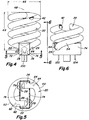
- FIGURES show a low pressure discharge lamp assembly A , particularly, a compact fluorescent lamp assembly, having an envelope B and a base or housing C .
- the envelope B is defined by an elongated tube 20 having first and second ends 22, 24 .
- the envelope is sealed from the external environment and contains a gas fill which is energized to a discharge state by applying and maintaining an electrical potential from a power source. Free electrons from the electrodes are accelerated by the potential difference and the kinetic energy of the electrons is transformed into internal energy of atoms in the gas fill upon collision with the free electrons. As the atoms relax to a lower energy state, internal energy of the atoms is dissipated as radiation.
- the gas fill includes mercury and a noble gas, such as argon, sealed in a gas tight manner in the discharge tube.
- Electrode assemblies are provided at the closed ends of the discharge tube where electrical leads 26, 28 extend outwardly from the sealed ends.
- the leads 26, 28 have a first portion disposed within the sealed tube and an outer portion external of the sealed tube for connection with the powered circuit. Suitable connections are made to the leads from a ballast or driving circuit 40 , details of which are known in the art.
- a phosphor coating 42 is provided on the internal wall of the discharge tube.
- the coating converts ultraviolet radiation from the mercury additive excited in the argon fill gas into visible light. Again, particular details of the coating are well known in the art so that further discussion herein is deemed unnecessary to a full and complete understanding of the present invention.
- the present invention reduces the overall length of the lamp by bending the ends 22, 24 radially inward.
- the prior art manner of terminating the first and second ends of the discharge lamp is shown.
- the legs of the discharge tube are oriented in a generally vertical direction which, as described above, contributes to an extended length of the compact fluorescent lamp that may not be compatible with harp sizes of conventional table lamps.
- the discharge tube is formed in a coiled configuration, preferably a double helix configuration, where the first and second ends are disposed at one end of the completed envelope.
- the double helix forms a continuous spiral path over a predetermined length 44 which is sufficient to provide a lumen output equivalent to a 100 watt incandescent lamp.
- the discharge tube has a generally constant diameter 46 over its entire longitudinal extent 44 . That is, the tube is formed into the double helix about a central or longitudinal axis 48 . As shown in FIGURE 1, the tube completes approximately one and a half turns in each helix, although a greater or lesser number of turns may be required to obtain different envelope lengths for a preselected lamp output.
- the coil configuration is the most compact structure for any given length and diameter of narrow tubing. Thus, the ability to further reduce the length or height of the envelope for an already compact structure becomes significant.
- each of the ends 22, 24 is turned radially inward at areas 52, 54, respectively.
- the diametrically opposite end portions are bent radially inward at 52, 54 so that the ends enter corresponding openings 62, 64 in the base.
- the ends enter the base on generally diametrically opposite portions thereof.
- the radial bend orients the ends generally perpendicular to the axis 48 . In this manner, pull-out forces exerted on the envelope in a direction generally parallel to the axis 48 will be effectively resisted by the radial mounting of the envelope in the base.
- the opening 62 if formed as a C-shaped groove, can be defined by a snap-fit structure represented by dotted line 64, 66 to complete the peripheral connection about the ends of the envelope.
- a structural arrangement may eliminate the need of any cement to secure the envelope to the base, or, if desired, may be used in conjunction with a reduced amount of cement. This, in turn, would lead to decreased costs and time associated with manufacture of the compact fluorescent lamp in accordance with known techniques.
- a pair of vertical walls or plates 70, 72 serve as sides of the upper portion of the ballast housing.
- Each plate has a radial opening 62, 64 that receives an inwardly directed end of the envelope.
- each plate serves as a backing to limit continued insertion of the opposite leg beyond the other plate as generally represented by regions 76, 78 (FIGURE 2).
- electrodes 82, 84 are spaced outwardly from the walls 72, 74 of the base. This is the region of highest temperature associated with the discharge lamp. Since the base is often formed of a plastic material, it is desirable to maximize the distance of the electrodes from the housing and provide sufficient heat sinking to provide good heat exchange with the external environment.
- the plastic wall functions as a heat shield in its own right to limit heat radiated by the electrodes from directly entering the ballast housing area.
- the radially bent ends are disposed in a generally horizontal direction and easily compartmentalized to prevent the heat generated at the electrodes from entering the ballast region of the base.
- the discharge tube ends advantageously provide a cold spot that fixes the vapor pressure of the mercury or amalgam in the lamp.
- the housing or base of FIGURES 1 - 3 is also provided with an eyelet 92 and externally threaded shell 94 on an end of the base for cooperation with a threaded socket of an associated lamp (not shown). Appropriate electrical connections are established between the eyelet and shell 92, 94 and the associated circuitry of the ballast so that power from an external source is regulated by the ballast to operate the discharge lamp.
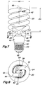
- FIGURES 4-6 illustrates the application of the present invention to a plug-in lamp configuration. Much of the structure is similar to that of the embodiment of FIGURES 1-3 so that like numerals refer to like elements and the previous description is applicable to this embodiment. As will be apparent, however, the ballast is not integrally formed in the housing, but is a separate component. Pin type connections 100, 102, and 104 extend from the base for a cooperative receipt in a ballast housing (not shown).
- ballast housing such as one using integrated circuits. It is contemplated that the scale and size of this type of housing will become increasingly smaller as ballast technology is developed. If, in fact, a ballast housing is miniaturized to be no larger than a standard Edison base used in incandescent lamps, a direct connection between the radially directed ends of the envelope of the ballast housing may be possible. In the meantime, a tapered arrangement as represented at 106 is necessary to complete the transition between the ballast region of the housing and the Edison-style base.
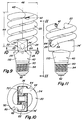
- FIGURES 9-11 represents a hybridization of concepts incorporated in the previous embodiments.
- a pair of plates 72', 74' provide for ease of connection of the lamp envelope to the base.
- the plates compartmentalize the ends of the discharge tube to provide advantageous heat transfer benefits in a manner as described above.
- a cylindrical portion or bottom region 110 of the base provides additional area for housing the ballast components than is provided in the embodiment of FIGURES 1-3.
- the ballast components are physically separated from the envelope by virtue of the compartmentalized plates that receive the ends of the envelopes.
- the electrodes are still positioned radially outward of the housing so that a temperature effect on the base is minimized.
- a compact fluorescent lamp formed in accordance with the teachings enumerated above results in a lamp that delivers approximately one thousand seven hundred (1700) lumens at one hundred (100) hours while dissipating approximately twenty four (24) watts.
- the discharge tube has an average inner diameter of approximately ten (10) mm in an argon gas fill pressurized to three to four (3-4) torr.
- the overall length of the envelope is approximately six hundred seventy (670) mm by directing the ends radially inward and non-essential leg length common in prior arrangements is eliminated to reduce the overall height of the lamp assembly.
- the ballast housing essentially overlaps the length of the first coil of the lamp when compared to prior arrangements due to the radial mounting of the envelope ends to the housing instead of forming vertically extending legs. These combined effects result in an overall reduction in lamp height of around thirteen (13) mm.
- the compact fluorescent lamp approximates the footprint of a one hundred fifty (150) watt incandescent lamp so that it fits within most table lamp harps and reflector fixtures.
- Compartmentalization of the heat radiated by the electrodes prevents the heat from directly entering the ballast housing. This can be accomplished without the addition of a heat shield between the ends of the envelope and the ballast component board, a common prior art solution which adds to the overall length of the lamp.
- the spacing of the electrodes from the ends of the tube also provides a cold spot that fixes the vapor pressure of mercury or amalgam.
- a compact fluorescent lamp in which both ends of the double helix or coil are dispo'sed on the same end of the lamp is provided.
- the overall lamp geometry provides for reduced height of the lamp by directing the ends of the envelope radially inward, rather than vertically downward, for mounting into the base.
- this geometry is equally applicable to lamps in which the base is integrally formed with the ballast components therein, or where the ballast is contained in a separate housing, and where the housing may adopt a number of different configurations.
Landscapes
- Engineering & Computer Science (AREA)
- Manufacturing & Machinery (AREA)
- Vessels And Coating Films For Discharge Lamps (AREA)
- Common Detailed Techniques For Electron Tubes Or Discharge Tubes (AREA)
Applications Claiming Priority (2)
| Application Number | Priority Date | Filing Date | Title |
|---|---|---|---|
| US414429 | 1995-03-31 | ||
| US08/414,429 US5705883A (en) | 1995-03-31 | 1995-03-31 | Reduced length compact fluorescent lamp and method of forming same |
Publications (3)
| Publication Number | Publication Date |
|---|---|
| EP0735567A2 true EP0735567A2 (fr) | 1996-10-02 |
| EP0735567A3 EP0735567A3 (fr) | 1999-01-13 |
| EP0735567B1 EP0735567B1 (fr) | 2003-04-23 |
Family
ID=23641414
Family Applications (1)
| Application Number | Title | Priority Date | Filing Date |
|---|---|---|---|
| EP96300492A Expired - Lifetime EP0735567B1 (fr) | 1995-03-31 | 1996-01-24 | Lampe à décharge |
Country Status (7)
| Country | Link |
|---|---|
| US (1) | US5705883A (fr) |
| EP (1) | EP0735567B1 (fr) |
| JP (1) | JPH0917378A (fr) |
| CN (1) | CN1104027C (fr) |
| CA (1) | CA2170071A1 (fr) |
| DE (1) | DE69627570T2 (fr) |
| MX (1) | MX9601238A (fr) |
Cited By (4)
| Publication number | Priority date | Publication date | Assignee | Title |
|---|---|---|---|---|
| DE19814244A1 (de) * | 1998-03-31 | 1999-10-07 | Walter Holzer | Gehäuse für Gasentladungslampen |
| KR20000024183A (ko) * | 2000-01-27 | 2000-05-06 | 최근대 | 이중나선 벌브형 전구식 형광등 |
| GB2310078B (en) * | 1996-01-24 | 2000-10-18 | Terence Milner | Lighting device |
| US7414358B2 (en) | 2001-11-14 | 2008-08-19 | Matsushita Electric Industrial Co., Ltd. | Fluorescent lamp and manufacturing method for arc tube |
Families Citing this family (24)
| Publication number | Priority date | Publication date | Assignee | Title |
|---|---|---|---|---|
| DE19548305C2 (de) * | 1995-12-22 | 2003-04-17 | Walter Holzer | Gasentladungsgefäß für Gasentladungslampen |
| DE19755680A1 (de) * | 1997-12-15 | 1999-06-17 | Holzer Walter Prof Dr H C Ing | Einseitig gesockeltes Gasentladungsgefäß für Energiesparlampen |
| US6064155A (en) * | 1998-05-04 | 2000-05-16 | Matsushita Electric Works Research And Development Labratory Inc | Compact fluorescent lamp as a retrofit for an incandescent lamp |
| US7928644B1 (en) * | 2000-08-22 | 2011-04-19 | General Electric Company | Low pressure discharge lamp with envelope having double helix shape and sealed ends |
| US6759797B2 (en) * | 2001-06-15 | 2004-07-06 | General Electric Company | Compact fluorescent lamp |
| US6935137B2 (en) * | 2001-10-09 | 2005-08-30 | General Electric Company | Method of and apparatus for forming discharge tubes of low-pressure discharge lamps |
| US7132799B2 (en) * | 2002-03-28 | 2006-11-07 | Matsushita Electric Industrial Co., Ltd. | Compact self-ballasted fluorescent lamp, fluorescent lamp and helical glass tube |
| CN100358084C (zh) * | 2002-03-29 | 2007-12-26 | 松下电器产业株式会社 | 发光管以及低压水银灯 |
| CN100498039C (zh) * | 2002-03-29 | 2009-06-10 | 松下电器产业株式会社 | 小型自镇流荧光灯 |
| US7196462B2 (en) * | 2002-06-12 | 2007-03-27 | Matsushita Electric Industrial Co., Ltd. | Arc tube with shortened total length, manufacturing method for arc tube, and low-pressure mercury lamp |
| JP4820051B2 (ja) * | 2002-06-12 | 2011-11-24 | パナソニック株式会社 | 発光管、発光管の製造方法及び低圧水銀ランプ |
| CN100380557C (zh) * | 2002-07-22 | 2008-04-09 | 松下电器产业株式会社 | 低压汞灯及其组装方法 |
| KR100492938B1 (ko) * | 2002-09-11 | 2005-05-30 | 강성진 | 컴팩트형 방전 램프 |
| JP3885032B2 (ja) * | 2003-02-28 | 2007-02-21 | 松下電器産業株式会社 | 蛍光ランプ |
| JP3990645B2 (ja) * | 2003-02-28 | 2007-10-17 | 松下電器産業株式会社 | 蛍光ランプ |
| US20050088076A1 (en) * | 2003-10-27 | 2005-04-28 | Chi-Jung Chu | Fluorescent lamp |
| WO2005067553A2 (fr) * | 2004-01-13 | 2005-07-28 | T-1 Lighting, Inc. | Dispositif d'eclairage ameliore |
| JP2005276515A (ja) * | 2004-03-23 | 2005-10-06 | Matsushita Electric Ind Co Ltd | 発光管、低圧水銀放電ランプ及び照明装置 |
| US7125159B2 (en) * | 2004-04-20 | 2006-10-24 | Sea Gull Lighting Products, Inc. | Non-defeatable fluorescent adapter for incandescent fixture |
| US20060045818A1 (en) * | 2004-09-02 | 2006-03-02 | Gregory Moreland | Combination coil type lamp and fragrance producing cartridge |
| CN1805106A (zh) * | 2005-01-11 | 2006-07-19 | 海鸥照明产品有限公司 | 荧光灯 |
| JP2008226814A (ja) * | 2006-09-29 | 2008-09-25 | Toshiba Lighting & Technology Corp | 電球形蛍光ランプおよび照明器具 |
| US20080265741A1 (en) * | 2007-04-29 | 2008-10-30 | Crystal Green Lighting Co., Ltd. | Semi-full helical luminous electronic energy-saving lamp |
| CN105972453A (zh) * | 2016-07-08 | 2016-09-28 | 何忠亮 | 一种led灯 |
Citations (3)
| Publication number | Priority date | Publication date | Assignee | Title |
|---|---|---|---|---|
| US4503360A (en) | 1982-07-26 | 1985-03-05 | North American Philips Lighting Corporation | Compact fluorescent lamp unit having segregated air-cooling means |
| DE4133077A1 (de) | 1991-10-02 | 1993-04-15 | Narva Gluehlampen | Niederdruckgasentladungslampe |
| WO1994029895A1 (fr) | 1993-02-24 | 1994-12-22 | Lee, Ok, Yun | Tube de type en double spirale pour lampe fluorescente, et lampe fluorescente du type ampoule comprenant un tel tube demontable |
Family Cites Families (17)
| Publication number | Priority date | Publication date | Assignee | Title |
|---|---|---|---|---|
| US2778462A (en) * | 1952-08-27 | 1957-01-22 | Gen Motors Corp | Fluid motor and transmission |
| US3886396A (en) * | 1971-10-10 | 1975-05-27 | Gen Electric | Fluorescent lamp with protective coating |
| US3764844A (en) * | 1972-04-28 | 1973-10-09 | A Schmidt | Gas discharge lamp and method for making same |
| US3953761A (en) * | 1974-04-03 | 1976-04-27 | Thomas Lo Giudice | Fluorescent light bulb for use in conventional incandescent bulb fixture |
| US3898495A (en) * | 1974-04-05 | 1975-08-05 | Westinghouse Electric Corp | Circular fluorescent lamp with two-piece snap-lock base |
| FR2507011A1 (fr) * | 1981-05-26 | 1982-12-03 | Desplat Raymond | Lampe a decharge du type tube a cathode froide courbe selon deux nappes |
| DE3432675A1 (de) * | 1984-09-05 | 1986-03-13 | Patent-Treuhand-Gesellschaft für elektrische Glühlampen mbH, 8000 München | Kompakte niederdruckentladungslampe |
| US4797594A (en) * | 1985-04-03 | 1989-01-10 | Gte Laboratories Incorporated | Reprographic aperture lamps having improved maintenance |
| GB2222874B (en) * | 1988-09-20 | 1992-11-11 | Toshiba Lighting & Technology | Tiltable lamp structure |
| US5204580A (en) * | 1988-09-20 | 1993-04-20 | Toshiba Lighting & Technology Corporation | Ring-shaped lamp device having bulb tiltable relative to base structure |
| EP0447957A3 (en) * | 1990-03-19 | 1992-04-29 | Walter Holzer | Compact fluorescent lamp |
| GB9015575D0 (en) * | 1990-07-16 | 1990-09-05 | Smiths Industries Plc | Radiation-emitting panels and display assemblies |
| DE4027783A1 (de) * | 1990-09-03 | 1992-04-30 | Holzer Walter | Gasentladungsgeraet fuer kompaktlampen |
| US5220236A (en) * | 1991-02-01 | 1993-06-15 | Hughes Aircraft Company | Geometry enhanced optical output for rf excited fluorescent lights |
| CA2076127A1 (fr) * | 1991-09-26 | 1993-03-27 | Louis R. Nerone | Montage electronique de ballast pour tube fluorescent compact |
| US5331168A (en) * | 1992-02-19 | 1994-07-19 | Beaubien David J | Reference grade solar ultraviolet band pyranometer |
| US5361017A (en) * | 1993-02-01 | 1994-11-01 | Astronics Corporation | Instrument panel and EL lamp thereof |
-
1995
- 1995-03-31 US US08/414,429 patent/US5705883A/en not_active Expired - Lifetime
-
1996
- 1996-01-24 EP EP96300492A patent/EP0735567B1/fr not_active Expired - Lifetime
- 1996-01-24 DE DE69627570T patent/DE69627570T2/de not_active Expired - Fee Related
- 1996-02-22 CA CA002170071A patent/CA2170071A1/fr not_active Abandoned
- 1996-03-27 JP JP7193296A patent/JPH0917378A/ja not_active Withdrawn
- 1996-03-28 CN CN96104135A patent/CN1104027C/zh not_active Expired - Lifetime
- 1996-03-29 MX MX9601238A patent/MX9601238A/es unknown
Patent Citations (3)
| Publication number | Priority date | Publication date | Assignee | Title |
|---|---|---|---|---|
| US4503360A (en) | 1982-07-26 | 1985-03-05 | North American Philips Lighting Corporation | Compact fluorescent lamp unit having segregated air-cooling means |
| DE4133077A1 (de) | 1991-10-02 | 1993-04-15 | Narva Gluehlampen | Niederdruckgasentladungslampe |
| WO1994029895A1 (fr) | 1993-02-24 | 1994-12-22 | Lee, Ok, Yun | Tube de type en double spirale pour lampe fluorescente, et lampe fluorescente du type ampoule comprenant un tel tube demontable |
Cited By (4)
| Publication number | Priority date | Publication date | Assignee | Title |
|---|---|---|---|---|
| GB2310078B (en) * | 1996-01-24 | 2000-10-18 | Terence Milner | Lighting device |
| DE19814244A1 (de) * | 1998-03-31 | 1999-10-07 | Walter Holzer | Gehäuse für Gasentladungslampen |
| KR20000024183A (ko) * | 2000-01-27 | 2000-05-06 | 최근대 | 이중나선 벌브형 전구식 형광등 |
| US7414358B2 (en) | 2001-11-14 | 2008-08-19 | Matsushita Electric Industrial Co., Ltd. | Fluorescent lamp and manufacturing method for arc tube |
Also Published As
| Publication number | Publication date |
|---|---|
| CN1140325A (zh) | 1997-01-15 |
| CA2170071A1 (fr) | 1996-10-01 |
| US5705883A (en) | 1998-01-06 |
| EP0735567A3 (fr) | 1999-01-13 |
| DE69627570D1 (de) | 2003-05-28 |
| EP0735567B1 (fr) | 2003-04-23 |
| DE69627570T2 (de) | 2004-04-08 |
| MX9601238A (es) | 1998-04-30 |
| CN1104027C (zh) | 2003-03-26 |
| JPH0917378A (ja) | 1997-01-17 |
Similar Documents
| Publication | Publication Date | Title |
|---|---|---|
| EP0735567B1 (fr) | Lampe à décharge | |
| MXPA96001238A (en) | Fluorescent lamp compact length reduciday method of forming the mi | |
| EP2156463B1 (fr) | Lampe fluorescente compacte à enveloppe extérieure et procédé de sa fabrication | |
| US6064155A (en) | Compact fluorescent lamp as a retrofit for an incandescent lamp | |
| US7042158B2 (en) | Compact fluorescent lamp, self-ballasted fluorescent lamp and luminaire | |
| EP2227820B1 (fr) | Lampe fluorescente compacte dotée de moyens formant support mécanique et aide à l'amorçage | |
| US7178944B2 (en) | Lighting apparatus | |
| JPH08171884A (ja) | バラスト一体型蛍光ランプ | |
| CN100426447C (zh) | 紧凑的自镇流的荧光灯 | |
| US5769530A (en) | Compact fluorescent lamp with extended legs for providing a cold spot | |
| CN100538988C (zh) | 尺寸可减小的电弧管和低压汞灯 | |
| EP1714303A2 (fr) | Dispositif fluorescent a decharge gazeuse avec support de lampe | |
| EP0601893B1 (fr) | Lampe fluorescente | |
| CN100358084C (zh) | 发光管以及低压水银灯 | |
| EP0682355A1 (fr) | Lampe fluorescente sous forme d'ampoule et son procede de fabrication | |
| JP3478369B2 (ja) | 環形蛍光ランプおよび照明器具 | |
| JP2002298608A (ja) | 電球形蛍光ランプ | |
| JP3427242B2 (ja) | 無電極蛍光ランプ | |
| JPH06196133A (ja) | 無電極蛍光ランプ | |
| KR100499198B1 (ko) | 무전극 무자심 방전램프 | |
| US8508113B2 (en) | Hybrid compact fluorescent lamp fixing method | |
| CN101315861A (zh) | 荧光灯 | |
| JP3473260B2 (ja) | 蛍光ランプ装置,電球形蛍光ランプ装置 | |
| JP2004095403A (ja) | 電球形蛍光ランプ | |
| JPH11288687A (ja) | 放電ランプ |
Legal Events
| Date | Code | Title | Description |
|---|---|---|---|
| PUAI | Public reference made under article 153(3) epc to a published international application that has entered the european phase |
Free format text: ORIGINAL CODE: 0009012 |
|
| AK | Designated contracting states |
Kind code of ref document: A2 Designated state(s): DE FR GB IT |
|
| PUAL | Search report despatched |
Free format text: ORIGINAL CODE: 0009013 |
|
| AK | Designated contracting states |
Kind code of ref document: A3 Designated state(s): DE FR GB IT |
|
| 17P | Request for examination filed |
Effective date: 19990713 |
|
| 17Q | First examination report despatched |
Effective date: 19991118 |
|
| GRAH | Despatch of communication of intention to grant a patent |
Free format text: ORIGINAL CODE: EPIDOS IGRA |
|
| GRAH | Despatch of communication of intention to grant a patent |
Free format text: ORIGINAL CODE: EPIDOS IGRA |
|
| GRAA | (expected) grant |
Free format text: ORIGINAL CODE: 0009210 |
|
| AK | Designated contracting states |
Designated state(s): DE FR GB IT |
|
| PG25 | Lapsed in a contracting state [announced via postgrant information from national office to epo] |
Ref country code: IT Free format text: LAPSE BECAUSE OF FAILURE TO SUBMIT A TRANSLATION OF THE DESCRIPTION OR TO PAY THE FEE WITHIN THE PRE;WARNING: LAPSES OF ITALIAN PATENTS WITH EFFECTIVE DATE BEFORE 2007 MAY HAVE OCCURRED AT ANY TIME BEFORE 2007. THE CORRECT EFFECTIVE DATE MAY BE DIFFERENT FROM THE ONE RECORDED.SCRIBED TIME-LIMIT Effective date: 20030423 Ref country code: FR Free format text: LAPSE BECAUSE OF NON-PAYMENT OF DUE FEES Effective date: 20030423 |
|
| REG | Reference to a national code |
Ref country code: GB Ref legal event code: FG4D |
|
| REF | Corresponds to: |
Ref document number: 69627570 Country of ref document: DE Date of ref document: 20030528 Kind code of ref document: P |
|
| PGFP | Annual fee paid to national office [announced via postgrant information from national office to epo] |
Ref country code: FR Payment date: 20040122 Year of fee payment: 9 |
|
| PLBE | No opposition filed within time limit |
Free format text: ORIGINAL CODE: 0009261 |
|
| STAA | Information on the status of an ep patent application or granted ep patent |
Free format text: STATUS: NO OPPOSITION FILED WITHIN TIME LIMIT |
|
| 26N | No opposition filed |
Effective date: 20040126 |
|
| EN | Fr: translation not filed | ||
| PGFP | Annual fee paid to national office [announced via postgrant information from national office to epo] |
Ref country code: DE Payment date: 20090302 Year of fee payment: 14 |
|
| PGFP | Annual fee paid to national office [announced via postgrant information from national office to epo] |
Ref country code: GB Payment date: 20090129 Year of fee payment: 14 |
|
| GBPC | Gb: european patent ceased through non-payment of renewal fee |
Effective date: 20100124 |
|
| PG25 | Lapsed in a contracting state [announced via postgrant information from national office to epo] |
Ref country code: DE Free format text: LAPSE BECAUSE OF NON-PAYMENT OF DUE FEES Effective date: 20100803 |
|
| PG25 | Lapsed in a contracting state [announced via postgrant information from national office to epo] |
Ref country code: GB Free format text: LAPSE BECAUSE OF NON-PAYMENT OF DUE FEES Effective date: 20100124 |