EP0735701B1 - Verfahren und Anordnung zur Übertragung mit Antennendiversity (geschaltete Antennen) mit ARQ-Verfahren - Google Patents
Verfahren und Anordnung zur Übertragung mit Antennendiversity (geschaltete Antennen) mit ARQ-Verfahren Download PDFInfo
- Publication number
- EP0735701B1 EP0735701B1 EP96302082A EP96302082A EP0735701B1 EP 0735701 B1 EP0735701 B1 EP 0735701B1 EP 96302082 A EP96302082 A EP 96302082A EP 96302082 A EP96302082 A EP 96302082A EP 0735701 B1 EP0735701 B1 EP 0735701B1
- Authority
- EP
- European Patent Office
- Prior art keywords
- markers
- transmitter
- type
- error detection
- receiver
- Prior art date
- Legal status (The legal status is an assumption and is not a legal conclusion. Google has not performed a legal analysis and makes no representation as to the accuracy of the status listed.)
- Expired - Lifetime
Links
Images








Classifications
-
- H—ELECTRICITY
- H04—ELECTRIC COMMUNICATION TECHNIQUE
- H04L—TRANSMISSION OF DIGITAL INFORMATION, e.g. TELEGRAPHIC COMMUNICATION
- H04L1/00—Arrangements for detecting or preventing errors in the information received
- H04L1/004—Arrangements for detecting or preventing errors in the information received by using forward error control
- H04L1/0056—Systems characterized by the type of code used
- H04L1/0067—Rate matching
- H04L1/0068—Rate matching by puncturing
-
- H—ELECTRICITY
- H04—ELECTRIC COMMUNICATION TECHNIQUE
- H04B—TRANSMISSION
- H04B7/00—Radio transmission systems, i.e. using radiation field
- H04B7/02—Diversity systems; Multi-antenna system, i.e. transmission or reception using multiple antennas
- H04B7/04—Diversity systems; Multi-antenna system, i.e. transmission or reception using multiple antennas using two or more spaced independent antennas
- H04B7/06—Diversity systems; Multi-antenna system, i.e. transmission or reception using multiple antennas using two or more spaced independent antennas at the transmitting station
- H04B7/0602—Diversity systems; Multi-antenna system, i.e. transmission or reception using multiple antennas using two or more spaced independent antennas at the transmitting station using antenna switching
- H04B7/0608—Antenna selection according to transmission parameters
- H04B7/061—Antenna selection according to transmission parameters using feedback from receiving side
-
- H—ELECTRICITY
- H04—ELECTRIC COMMUNICATION TECHNIQUE
- H04L—TRANSMISSION OF DIGITAL INFORMATION, e.g. TELEGRAPHIC COMMUNICATION
- H04L1/00—Arrangements for detecting or preventing errors in the information received
- H04L1/004—Arrangements for detecting or preventing errors in the information received by using forward error control
- H04L1/0056—Systems characterized by the type of code used
- H04L1/0071—Use of interleaving
-
- H—ELECTRICITY
- H04—ELECTRIC COMMUNICATION TECHNIQUE
- H04L—TRANSMISSION OF DIGITAL INFORMATION, e.g. TELEGRAPHIC COMMUNICATION
- H04L1/00—Arrangements for detecting or preventing errors in the information received
- H04L1/02—Arrangements for detecting or preventing errors in the information received by diversity reception
- H04L1/04—Arrangements for detecting or preventing errors in the information received by diversity reception using frequency diversity
-
- H—ELECTRICITY
- H04—ELECTRIC COMMUNICATION TECHNIQUE
- H04L—TRANSMISSION OF DIGITAL INFORMATION, e.g. TELEGRAPHIC COMMUNICATION
- H04L1/00—Arrangements for detecting or preventing errors in the information received
- H04L1/02—Arrangements for detecting or preventing errors in the information received by diversity reception
- H04L1/06—Arrangements for detecting or preventing errors in the information received by diversity reception using space diversity
-
- H—ELECTRICITY
- H04—ELECTRIC COMMUNICATION TECHNIQUE
- H04L—TRANSMISSION OF DIGITAL INFORMATION, e.g. TELEGRAPHIC COMMUNICATION
- H04L1/00—Arrangements for detecting or preventing errors in the information received
- H04L1/12—Arrangements for detecting or preventing errors in the information received by using return channel
- H04L1/16—Arrangements for detecting or preventing errors in the information received by using return channel in which the return channel carries supervisory signals, e.g. repetition request signals
- H04L1/18—Automatic repetition systems, e.g. Van Duuren systems
- H04L1/1812—Hybrid protocols; Hybrid automatic repeat request [HARQ]
- H04L1/1819—Hybrid protocols; Hybrid automatic repeat request [HARQ] with retransmission of additional or different redundancy
-
- H—ELECTRICITY
- H04—ELECTRIC COMMUNICATION TECHNIQUE
- H04L—TRANSMISSION OF DIGITAL INFORMATION, e.g. TELEGRAPHIC COMMUNICATION
- H04L1/00—Arrangements for detecting or preventing errors in the information received
- H04L1/12—Arrangements for detecting or preventing errors in the information received by using return channel
- H04L1/16—Arrangements for detecting or preventing errors in the information received by using return channel in which the return channel carries supervisory signals, e.g. repetition request signals
- H04L1/18—Automatic repetition systems, e.g. Van Duuren systems
-
- H—ELECTRICITY
- H04—ELECTRIC COMMUNICATION TECHNIQUE
- H04L—TRANSMISSION OF DIGITAL INFORMATION, e.g. TELEGRAPHIC COMMUNICATION
- H04L1/00—Arrangements for detecting or preventing errors in the information received
- H04L2001/0098—Unequal error protection
Definitions
- the present invention relates generally to the field of communications, and particularly to the field of wireless communication over slow fading channels.
- Transmission errors are abundant on many wireless communication channels.
- One cause is multipath fading, wherein multiple copies of an information packet reach the receiver over multiple paths with different time delays, amplitudes, and phases due to scattering and reflection. As the multiple copies of the information packet destructively interfere with each other the level of the received signal falls.
- the channel If the level of the received signal falls below a usable threshold level, (characterized by a very small signal-to-noise ratio (SNR)) the channel is said to be in a deep fade.
- a usable threshold level characterized by a very small signal-to-noise ratio (SNR)
- SNR signal-to-noise ratio
- Antenna diversity is used to reduce the effects of multipath fading on channels with slow fading characteristics.
- One form of antenna diversity is switched antenna diversity.
- multiple antennas provide multiple channels, having independent multipath fading characteristics, to be used one at time as existing channel conditions change.
- the receiver constantly compares the received signal strength to a predetermined threshold which detects when the channel is in a deep fade. If the received signal falls below the threshold, an explicit message is sent over a feedback channel to inform the transmitter of the bad channel condition and to request that the transmitter switch to a different antenna, i.e., another channel.
- European Patent Application No. 622 911 A2 discloses a diversity transmission strategy in which a base station determines and tracks current preferred transceivers for communicating with each of a plurality of mobile stations.
- the present invention provides a cost effective switched antenna diversity transmission method and system for transmitting information over slow fading channels which more efficiently uses a feedback communication channel.
- the present invention does not require dynamic thresholding to determine the condition of the channel, and thus the receiver can be built without the expense of additional thresholding circuitry.
- the present invention does not use a feedback channel just for transmitting explicit channel condition messages or explicit requests for the transmitter to change antennas when a given channel is bad. Rather, the present invention uses the feedback channel with an ARQ error protection protocol to request retransmission of erroneous packets, to implicitly indicate the existing channel condition, and when the channel is bad, to switch antennas .
- the present invention provides a transmitter and a corresponding transmitting method according to the accompanying claims.
- the present invention uses an ARQ protocol for error protection.
- Other protocols including hybrid ARQ protocols, may be used.
- ARQ protocols use a feedback channel over which the receiver can request retransmission of erroneous information packets, and in doing so, provide relatively error-free wireless communication channels.
- the transmitter in an ARQ-based transmission system encodes the information packets to be transmitted with an error detection code to enable the receiver to detect whether there are any erroneous information packets to retransmit.
- the transmitter waits for an acknowledgement from the receiver. If no errors are detected in a received information packet, the information packet is delivered to the data sink and a positive acknowledgement is sent back to the transmitter, which, in response, sends the next information packet to the receiver. If, on the other hand, an error is detected in the received information packet, the receiver discards the information packet and a negative acknowledgement is sent to the transmitter which, in response, re-transmits the erroneous information packet.
- Hybrid ARQ protocols use both an error detection code and an error correction code.
- an erroneous information packet is re-transmitted only if it cannot be corrected by the error correction code.
- the packets are encoded with an error correction code only when necessary, such as, for example, in response to a negative acknowledgement.
- the present invention uses switched antenna diversity to reduce the effects of multi-path fading on slow fading channels and thus the number of ARQ re-transmissions that are needed.
- the switched antenna diversity of the present invention is responsive to the negative acknowledgement of the ARQ and hybrid ARQ protocols rather than the explicit channel condition messages and requests to switch antennas associated with dynamic thresholding.
- VLSI Very large scale integration
- FIG. 1A shows a transmitter 50 and Fig. 1B shows a receiver 52.
- the transmitter 50 in Fig. 1A includes am error detection encoder 62, a modulator 64, an antenna switch 66, and multiple transmission antennas (TA 1 -TA M ) 67 which include associated transmission circuitry (comprising conventional carrier, pulse shaping, and power amplification circuits). Also included is a repeat controller 92.
- the receiver 52 in Fig. 1B includes one or more reception antennas (RA) 69 which include associated reception circuitry (comprising, e.g., low noise amplifiers, RF/IF band-pass filters, and a match filter).
- the receiver 52 also includes a demodulator 71, an error detection decoder 73, and a repeat generator 90.
- the transmitter 50 receives information packets from a data source 60, as shown in Fig. 1A .
- the information packets are encoded by the error detection encoder 62 with a suitable error detection code known to those of ordinary skill in the art.
- the error detection code enables the receiver to detect transmission errors in the information packets.
- One suitable error detection encoder is a CRC-16 encoder which encodes the information packets with a 16-bit cyclic redundancy code.
- the packets are modulated by modulator 64 and transmitted by one of the antennas (TA 1 -TA M ) 67 over a forward channel 68 of the communication medium to the receiver 52 in Fig. 1B .
- Any suitable modulator known to those of ordinary skill in the art may be used for modulator 64.
- One suitable modulator is a 4-DPSK modulator.
- the reception antenna 69 of receiver 52 is used to receive the information packets that are transmitted. Once received, the packets are demodulated by a suitable, complementary demodulator 71.
- a suitable demodulator is a 4-DPSK demodulator.
- the error detection decoder 73 decodes the demodulated information packets to determine whether there are transmission errors in any of the packets.
- the decoder 73 normally regenerates the error detection code for each information packet and compares it against the error detection code transmitted with the information packet. If the two codes match, presumably there is no error in the transmitted packet. If the two codes do not match, there is one or more errors in the transmitted packet.
- the error detection encoder 73 may be any suitable, complementary error detection decoder. For example, for a CRC-16 encoder, a suitable decoder would be a CRC-16 decoder.
- the packet is forwarded to data sink 75 and a positive acknowledgement (ACK) is sent by repeat generator 90 over feedback channel 91 to transmitter 50.
- ACK positive acknowledgement
- the repeat controller 92 of transmitter 50 sends the next data packet.
- NAK negative acknowledgement
- the repeat controller 92 of transmitter 50 responds to this request by re-transmitting the erroneous information packet.
- Each transmitted packet may be stored before transmission in a buffer or other suitable memory device so that it is readily available for retransmission.
- the transmitter 50 also responds to the negative acknowledgement (NAK) by actuating switch 66 which, in turn, changes from the current transmit antenna to another one of the multiple transmit antennas 67 for transmitting information packets to the receiver.
- NAK negative acknowledgement
- the switch 66 may be any suitable device known to those of ordinary skill in the art which functions to change antennas.
- the switch 66 may be an electronic switch or a magnetic switch.
- switch 66 may be a hardware switch or a programmable software switch.
- the present invention is particularly suited for JPEG image transmission.
- the present invention therefore may be used with the unequal error protection ARQ embodiments of the concurrently filed Weerackody patent document EP0735774, filed on March 31, 1995 , ("the Weerackody JPEG application").
- JPEG is the international standard for still image compression. JPEG is named after the group that developed the international standard -- the Joint Photographic Experts Group. A complete description of the JPEG standard is given in W.B. Pennebaker, J.L. Mitchell, JPEG Still Image Data Compression Standard (Van Norstrand Reinhold, New York 1993).
- JPEG compressed image data contains two classes of segments: (i) entropy coded segments, representing 16 x 16 blocks of the image, and (ii) markers or marker segments, which contain header information, transformation and quantization tables, and other information required for the JPEG decoder to interpret and decode the entropy coded image data. Included among the markers are restart markers which separate the entropy coded segments.
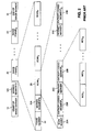
- Fig. 2 shows the structure of a typical JPEG coded image 50.
- a start of image marker 10 and marker segments 10A begin one or more image frames 20 (i.e., the compressed image data stream), and an end of image marker 30 terminates the image frame or frames.
- the marker segments 10A define quantization tables, entropy-coding (transformation) tables, and other miscellaneous parameters.
- a frame header 22 and marker segments 22A are generated at the beginning of each image frame 20.
- the frame header 22 begins with a start of frame marker followed by parameter values needed for decoding the frame.
- the frame header defines the basic attributes of the image, including image size, number of image components, the mode of compression, and the entropy coder used within the frame.
- marker segments 22A also define quantization tables, entropy coding (transformation) tables, and other miscellaneous parameters.
- Each image frame 20 is composed of one or more scans 23 through the image data, where a scan is a single pass through the data for one or more components of the image.
- the components of each scan are grouped into one or more entropy coded segments 23B which are separated by restart markers 23C.
- the components in each entropy coded segment are further grouped into one or more minimum coded units ("MCUs") generally representing 16 x 16 blocks of the image.
- MCUs minimum coded units
- the scan header 23A begins with a start of scan marker followed by parameter values needed for decoding the scan, such as the number of components in the scan and the scan component specification.
- Marker segments begin with a "marker” which is a two-byte hexadecimal code or word.
- the first byte is always a byte-aligned Oxff (Ox representing that the bytes in the image data stream are in hexadecimal form and the hexadecimal byte ff signifying a marker).
- the second byte is a "marker code” which identifies the function of the marker segment.
- the second byte is always a non-zero byte.
- the start of image marker is Oxffd8 and the end of image marker is Oxffd9.
- the byte ff denotes a marker
- the marker codes d8 and d9 identify the markers as the start of image and end of image markers, respectively.
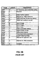
- the tables in Figs. 3A and 3B list the markers in a JPEG image: the table in Fig. 3A includes the start of frame markers (defining the entropy encoding procedure used), and the table in Fig. 3B includes all of the other, non-start of frame markers. These markers fall into two categories: those without parameters, and those followed by a fixed, undefined, or variable length sequence of parameters. A "V" notation in the length column of the tables in Figs.
- 3A and 3B represents a variable length parameter with a known structure; an "N" notation in the length column represents that no parameter sequence follows the marker; a "U” notation in the length column represents that the parameter sequence is undefined; and a numeric notation in the length column represents a fixed number of parameter bytes following the marker.
- the restart marker OxffdO has no parameters; the parameters of the define restart interval marker Oxffdd are contained in the 4 bytes immediately following Oxffdd; and the start of scan marker Oxffda contains a variable-length parameter sequence.
- the first parameter in any marker segment is always a two-byte code representing the length of the parameter sequence.
- a two-byte code 0x0043 following the quantization table marker Oxffdb would represent that there are 67 parameter bytes following the marker, including the two-byte length parameter.
- Markers with parameters following them are generally referred to as marker segments but the terms are used interchangeably in this application.
- the markers or marker segments have been determined to be more sensitive than the entropy coded segments.
- the marker segments are defined as Type-I information and the entropy coded segments are defined as Type-II information.
- the Type-I information may be further separated into Type-IA and Type-IB information.
- the restart markers are defined as Type-IB information and the other markers are defined as Type-IA information.
- the transmission system of the Weerackody JPEG patent application takes into account the sensitivity of each of the different types of JPEG information and uses "unequal error protection" during transmission.
- the most powerful error protection is applied to the Type-IA informationwhich is the most sensitive to transmission errors.
- the same or a lesser level of protection is applied to the Type-IB information.
- the lowest level of error protection is applied to the Type-II information -- the least sensitive of the three types of information.
- the power of an error protection protocol is usually measured by its minimum "free distance,” which is a term known to those of ordinary skill in the art. The greater the free distance of an error protection protocol the more powerful the error protection. Error protection power may also be measured by the average bit error rate (BER) for the same signal-to-noise ratio (SNR), but only if the BER is relatively constant over time. The smaller the BER of an error protection protocol the more powerful the error protection.
- Applying unequal error protection serves to reduce the overhead or bandwidth (i.e., the number of redundant bits) required for error protection, and thereby increases the throughput of the transmission system and more efficiently uses the communication channel.
- Type-IA information typically takes up less than 1% of the JPEG image data stream
- Type-IB information typically takes up only 5-10% of the JPEG image data stream.
- the rest of the JPEG image data stream consists of the least error sensitive Type-II information.
- the second illustrative embodiment of the present invention combines the switched antenna diversity system of the present invention with one of the unequal error protection ARQ embodiments set forth in the Weerackody JPEG patent application.
- the second illustrative embodiment of the present invention is shown in Figs. 4A and 4B .
- this embodiment of the present invention uses an ARQ protocol for the Type-I JPEG information and a less powerful forward error correction (FEC) code for the Type-II information.
- FEC forward error correction
- a transmitter 50A is shown in Fig. 4A and a receiver 52A is shown in Fig. 4B .
- the transmitter in Fig. 4A comprises, by way of example, a separator 61, an error detection encoder 62, an error correction encoder 78, block interleaver 79, 4-DPSK modulator 80, a multiplexer 65, a switch 66, multiple antennas (TA 1 -TA M ) 67 with associated transmission circuits, and a repeat controller 92.
- the receiver 52A in Fig. 4B comprises, by way of example, a reception antenna (RA) 69 with associated reception circuits, a demultiplexer 70, 4-DPSK demodulators 71 and 81, block deinterleaver 82, an error detection decoder 73, an error correction decoder 83, a combiner 74, and a repeat generator 90.
- RA reception antenna
- the transmitter 50A in Fig. 4A receives a JPEG image from data source 60, for example, a JPEG encoder, separates the JPEG image into Type-I and Type-II information, and transmits the Type-I and Type-II information from one of the antennas 67 over a first forward channel 68 of a communication medium to the receiver 52A in Fig. 4B .
- the transmitter 50A sends the Type-I and Type-II information over the first forward channel 68 in multiplexed packets as illustrated, for example, in Fig. 5A .
- the Type-I and Type-II information packets are processed and, if no errors are detected, they are recombined by combiner 74 into a JPEG structure and transferred to the data sink 75, which may be, for example, a JPEG decoder. If errors are detected in the information packets, a retransmission request is sent by repeat generator 90 to transmitter 50A over the feedback channel 91 to retransmit the erroneous information packets from a second antenna 67 over a second forward channel 68 of the communication medium.
- the separator 61 in Fig. 4A separates the JPEG image into Type-I and Type-II information.
- the separator 61 may be, for example, a digital signal processor (DSP) with suitable software for separating the JPEG image into Type-I and Type-II information.
- DSP digital signal processor
- Type-I information is the most sensitive to transmission errors and Type-II information is the least sensitive.
- a DSP may be programmed to separate the Type-I information from the Type-II information for a single frame, single scan JPEG image.
- Other methods will be readily apparent to those of ordinary skill in the art for JPEG images having one or more frames 20 and one or more scans 23.
- the DSP in this example examines the incoming bytes of the JPEG image for the hexadecimal byte ff, which denotes a marker. If an ff byte is detected, the DSP examines the next byte in the data stream, namely the marker code which describes the function of the marker. The purpose here is to determine whether the marker also includes a segment of parameters which will follow the marker in the data stream.
- the DSP knows that the marker is a start of image marker which has no parameters, as shown in the table in Fig. 3B . In this case, the DSP separates the entire two-byte marker (ffd8) from the JPEG stream.
- the DSP knows that the marker is a define quantization table marker (ffdb) which has a variable length sequence of parameters following it in the data stream.
- ffdb defines quantization table marker
- the DSP examines the next two bytes in the data stream after the two-byte marker to determine the number of parameter bytes following the marker. The DSP then separates the two-byte marker and its parameter bytes from the JPEG data stream.
- a byte is not determined to be a marker or marker segment it is considered Type-II entropy coded information and sorted as such from the JPEG data stream.
- the DSP In addition to separating the Type-I information from the Type-II information, the DSP also appends certain position information to the Type-I information so that the JPEG image structure can be recreated at the receiver. Various ways of doing this for one or more image frames 20, and one or more scans 23, will be readily apparent to those of ordinary skill in the art.
- One way the DSP can code the positions of the end of image marker and the restart markers is to keep a running count of the number of bytes in the JPEG data stream and use the byte number of the first restart marker (ffdO) as the starting position for the modulo 8 sequence of restart markers. For example, if the first restart marker (ffdO) is the 300th byte in the data stream, then its byte number is 300.
- the DSP can identify the relative byte positions of the remaining restart markers in the modulo 8 sequence (ffd1-ffd7). Specifically, the DSP may assign a byte number to each subsequent restart marker which corresponds to the number of entropy coded bytes between it and the previous restart marker.
- the DSP may identify its position by its byte number in the data stream. If there are 400 bytes in the JPEG image, then the position of the end of image marker will be 400.
- the positions of the restart markers are transmitted to the receiver without the restart markers themselves. This is because the restart markers occur in a known predetermined pattern (modulo 8 sequence: OxffdO, Oxffdl, Oxffd2, Oxffd3, Oxffd4, Oxffd5, Oxffd6, and Oxffd7) which can be generated at the receiver.
- the Type-I and Type-II information packets are, by way of example, encoded along separate Type-I and Type-II channels, as shown Fig. 4A .
- the Type-I information packets are encoded by the error detection encoder 62, which may be a CRC-16 encoder.
- a 4-DPSK modulator 64 modulates the encoded Type-I information packets, but any suitable modulator known to those of ordinary skill in the art may be used in its place.
- the Type-II information packets are encoded by encoder 83 for error correction using an FEC code, for example, a rate 1/2, memory 4 convolutional code.
- FEC code for example, a rate 1/2, memory 4 convolutional code.
- the convolutional code provides less powerful error protection for the Type-II information than the ARQ error protection that is afforded the Type-I information.
- the error correction encoded Type-II information packets are interleaved by block interleaver 83, which provides some limited time diversity.
- the block interleaver 83 writes the bits of each encoded Type-II packet into an m x n memory matrix in a column-wise fashion and then reads them out row-wise.
- the interleaver randomizes the burst errors likely to occur on slow fading channels. If a burst error of length n occurs, the interleaver functions to effectively convert the burst error into single bit errors.
- the modulated Type-I and Type-II information packets are multiplexed by multiplexer 65.
- the purpose here is to use the time slots (t 1 in Fig. 5A ) left idle after each Type-I packet transmission when the transmitter is waiting for a positive or negative acknowledgement from the receiver.
- Fig. 5A shows one example of multiplexed Type-I and Type-II information packets.
- the multiplexer multiplexes L Type-II information packets in between consecutive Type-I information packets.
- L can be fixed or variable.
- more than one Type-I information packet can be transmitted after each group of L Type-II information packets, as shown, for example, in Fig. 5C .
- the multiplexed Type-I and Type-II information packets are transmitted by one of the antennas 67 (which include associated transmission circuitry) over a first forward channel 68 to receiver 52A for processing.
- the multiplexed Type-I and Type-II information packets are received by the reception antenna 69 of receiver 52A, and then demultiplexed along separate decoding channels by demultiplexer 70.
- the Type-I information packets are demodulated by a complementary 4-DPSK demodulator 71 and then decoded by a complementary error detection decoder 73.
- a complementary error detection decoder 73 For example, if a CRC-16 error detection encoder is used to encode the Type-I information packets, a CRC-16 decoder is normally used to decode the Type-II packets.
- the function of the error detection decoder 73 is to re-generate the error detection code for each information packet and compare it with the error detection code that was transmitted with the Type-I information packet. If the two codes match, presumably there is no error in the transmitted packet. If the two codes do not match, there is at least one error in the transmitted packet.
- the erroneous Type-I information packet is discarded and a negative acknowledgement is transmitted by the repeat generator 90 over feedback channel 91.
- the repeat controller 92 and switch 66 cause transmitter 50A to retransmit the erroneous information packet over a second forward channel.
- the packet stream in Fig. 5B shows the same Type-I information packet (packet 1) being re-transmitted.
- the Type-I information packet is forwarded to combiner 74 and a positive acknowledgement is sent by repeat generator 90 over feedback channel 91 to transmitter 50A.
- repeat controller 92 causes transmitter 50A to transmit the next data packet, as illustrated in Fig. 5A .
- the Type-II information packets are demodulated by a complementary 4-DPSK de-modulator 81, as shown in Fig. 4B .
- the Type-II information packets are de-interleaved by the deinterleaver 82.
- the deinterleaver 82 performs the inverse operation of interleaver 63.
- the bits of the incoming Type-I information packets are stored row-wise in an m x n memory matrix and read out column-wise.
- the Type-II information packets are then passed to the error correction decoder 83.
- the Viterbi decoding algorithm is typically used by the error correction decoder 83 to decode a convolutional code. It will be apparent to those of ordinary skill in the art that other decoding algorithms may be used which are suitable for decoding the error correction encoded Type-II information.
- the combiner 74 combines the Type-I and Type-II information packets into a structure suitable for the data sink 75, which normally will be the original JPEG structure.
- the combiner 69 may be a digital signal processor (DSP) which is programmed to combine the Type-I and Type-II information.
- DSP digital signal processor
- the DSP may be programmed to place the first restart marker and the end of image marker at their respective byte number positions in the data stream.
- Each of the other restart markers is placed at a byte position relative to the preceding restart marker.
- the relative position of each restart marker was coded by separator 61 as the number of Type-II information bytes after the preceding restart marker.
- the DSP may also be further programmed to generate the modulo 8 sequence of restart markers at the coded relative byte positions.
- the Type-I information is further separated into Type-IA and Type-IB information, wherein the Type-IA information is provided with more powerful error protection than the Type-IB information.
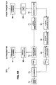
- the third illustrative embodiment is shown in Figs. 4C and 4D .
- a transmitter 50B is shown in Fig. 4C and a receiver 52B is shown in Fig. 4D .
- the separator 61 functions to separate the JPEG image into Type-I, Type-IB, and Type-II information
- the combiner 74 functions to combine all three types of information into a JPEG structure suitable for the data sink 75.
- the separator DSP of the second embodiment may be programmed to further separate the Type-I information into Type-IA and Type-IB information.
- the DSP may separate or sort the restart markers from the other Type-I markers using the second byte of each marker which identifies its function. As shown in the table in Fig. 3B , if the byte after the ff byte is d0-d7, the marker is a restart marker and the DSP will separate it from JPEG data stream as Type-IB information.
- Position information may be coded by the separator as already described for the second illustrative embodiment.
- the combiner DSP may also combine all three types of information in the manner described above for the second illustrative embodiment.
- This third embodiment is a modification of the second embodiment shown in Figs. 4A and 4B .
- the transmitter 50A (now transmitter 50B in Fig. 4C ) has been modified to include an additional encoding channel for the Type-IB information.
- the Type-IA information is still processed along the same ARQ-based encoding channel as the Type-1 information in Fig. 4A .
- the Type-IB encoding channel of transmitter 50B in Fig. 4C includes an error correction encoder 78A, a block interleaver 79A, and a 4-DPSK modulator 80A. These functional blocks correspond to encoder 78, block interleaver 73, and modulator 80 described above in connection with the Type-II decoding channel of transmitter 50A in Fig. 4A .
- the error correction encoder 78A uses the same less powerful, convolutional code as used in the error correction encoder 78 for the Type-II information, namely a rate 1/2, memory 4 convolutional code.
- Figs. 4B and 4D By comparison of Figs. 4B and 4D , one can see that the receiver 52A of Fig. 4B (now receiver 52B of Fig. 4D ) has also been modified to include a separate decoding channel for the Type-IB information.
- the Type-IA information is decoded on the same Type-I ARQ-based encoding channel shown in Fig. 4B .
- the Type-IB decoding channel of receiver 52B in Fig. 4D includes a demodulator 81A, a block interleaver 82A, and an error correction decoder 83A.
- the decoding process for the Type-IB information is the same as the decoding process used for the Type-II information because the same convolutional code was used for both the Type-IB and Type-II information in this illustrative embodiment.
- the Viterbi algorithm is typically used to decode the convolutional code used with the Type-IB information.
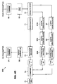
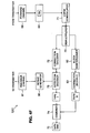
- FIG. 4E shows a transmitter 50C and Fig. 4F shows are receiver 52C. They are modifications of the transmitter 50B and receiver 52B of Figs. 4C and 4D , respectively.
- This embodiment uses a hybrid ARQ protocol.
- the hybrid protocol is implemented by the inclusion of an error correction encoder 63 in transmitter 50B of Fig. 4C and by the inclusion of a complementary error correction decoder 72 in receiver 52B of Fig. 4D .
- the purpose is to correct the errors in an erroneous packet before requesting retransmission of the erroneous packet.
- any suitable error correction code to known to those of ordinary skill in the art may be used.
- the present invention multiplexes the Type-I and Type-II information packets in advance of modulation. And on the receiving end, the Type-I and Type-II information packets are demodulated before being demultiplexed.
- FIGs. 4E and 4F This illustrative embodiment is shown in Figs. 4E and 4F .
- a transmitter 50D is shown in Fig. 4G and a receiver 52D is shown in Fig. 4H .
- the transmitter 50D is a modification of the transmitter 50A shown in Fig. 4A .
- the multiplexer 65 of Fig. 4A has been placed in advance of any modulation, and only modulator 64 is used to modulate the multiplexed Type-I and Type-II information packets.
- a complementary receiver 52D is shown in Fig. 4H .
- Receiver 52D is a modification of the receiver 52A in Fig. 4B .
- the receiver 52A of Fig. 4B has been modified to place the demultiplexer 70 after the demodulation of the Type-I and Type-II information packets.
- only demodulator 71 remains for demodulating the interleaved Type-I and Type-II information packets.
- the advantages of the present invention are best achieved on slow fading channels with relatively small packet sizes and multiplex ratios.
- significant performance gains can be achieved on slow fading channels with a large number of transmit antennas.
Landscapes
- Engineering & Computer Science (AREA)
- Computer Networks & Wireless Communication (AREA)
- Signal Processing (AREA)
- Detection And Prevention Of Errors In Transmission (AREA)
- Radio Transmission System (AREA)
Claims (16)
- Sender (50) zum Übertragen von Informationspaketen über ein drahtloses Kommunikationsmedium an einen Empfänger (52), umfassend:Einen Fehlerdetektionscodierer (62) zum Codieren der Informationspakete mit einem Fehlerdetektionscode;einen Modulator (64) zum Modulieren der mit der Fehlerdetektion codierten Informationspakete;eine erste Antenne zum Übertragen der modulierten Informationspakete über einen ersten Vorwärtskanal des Kommunikationsmediums an den Empfänger; undeine zweite Antenne zum Übertragen der modulierten Informationspakete über einen zweiten Vorwärtskanal des Kommunikationsmediums an den Empfänger anstelle der ersten Antenne;
GEKENNZEICHNET DURCH:Einen Schalter (66) zum Schalten von der ersten Antenne zur zweiten Antenne für die Übertragung der modulierten Informationspakete in Reaktion auf eine über einen Rückkopplungskanal des Kommunikationsmediums übertragene negative Quittierung von dem Empfänger;wobei der Sender dafür konfiguriert ist, ein JPEG-Bild mit ungleich gewichtetem Fehlerschutz über das drahtlose Kommunikationsmedium an den Empfänger zu übertragen, wobei der Sender weiterhin umfasst:Einen Zerteiler zum Zerteilen des JPEG-Bildes in Markierungssegmente und entropiecodierte Segmente;wobei bei der Fehlerdetektionscodierer für das Codieren der Markierungssegmente mit dem Fehlerdetektionscode ausgelegt ist; undwobei der Modulator für das Modulieren der codierten Markierungssegmente und der entropiecodierte Segmente für die Übertragung über entweder die erste oder die zweite Antenne ausgelegt ist. - Sender nach Anspruch 1, wobei der Fehlerdetektionscodierer ein CRC-16-Codierer ist.
- Sender nach Anspruch 1, wobei der Modulator ein 4-DPSK-Modulator ist.
- Sender nach Anspruch 1, wobei der Schalter ein Hardware-Schalter, oder ein programmierbarer Schalter, oder ein elektronischer Schalter, oder ein Magnetschalter ist.
- Verfahren zum Übertragen von Informationspaketen über ein drahtloses Kommunikationsmedium an einen Empfänger (52), umfassend:Codieren der Informationspakete mit einem Fehlerdetektionscode;Modulieren der mit der Fehlerdetektion codierten Informationspakete;Übertragen der modulierten Informationspakete über einen ersten Vorwärtskanal des Kommunikationsmediums von einer ersten Antenne an den Empfänger; GEKENNZEICHNET DURCH:Schalten, in Reaktion auf eine über einen Rückkopplungskanal des Kommunikationsmediums übertragene negative Quittierung von dem Empfänger, von der ersten Antenne zu einer zweiten Antenne für die Übertragung der modulierten Informationspakete;wobei das Verfahren das Übertragen eines JPEG-Bildes über das drahtlose Kommunikationsmedium an den Empfänger mit ungleich gewichtetem Fehlerschutz umfasst, wobei das Verfahren weiterhin umfasst:Zerteilen des JPEG-Bildes in Markierungssegmente und entropiecodierte Segmente;
undCodieren der Markierungssegmente mit dem Fehlerdetektionscode;wobei der Schritt des Modulierens das Modulieren der codierten Markierungssegmente und der entropiecodierten Segmente für die Übertragung über entweder die erste oder die zweite Antenne umfasst. - Sender nach Anspruch 1, weiterhin umfassend:Einen Fehlerkorrekturcodierer;wobei der Fehlerkorrekturcodierer dazu ausgelegt ist, die entropiecodierten Segmente mit einem Fehlerkorrekturcode zu codieren; undwobei der Modulator dazu ausgelegt ist, die codierten Segmente für die Übertragung über entweder die erste oder die zweite Antenne zu modulieren.
- Sender nach Anspruch 1 oder 6, wobei der erste Vorwärtskanal ein langsam schwindender Kanal ist.
- Sender nach Anspruch 1 oder 6, wobei der zweite Vorwärtskanal ein langsam schwindender Kanal ist.
- Sender nach Anspruch 6 wobei der Zerteiler ein digitaler Signalprozessor ist.
- Sender nach Anspruch 6, wobei der digitale Signalprozessor ein AT&T DSP32C ist.
- Sender nach Anspruch 6, wobei der Fehlerkorrekturcodierer die entropiecodierten Segmente mit einem Rate 1/2-Speicher 4-Faltungscode codiert.
- Sender nach Anspruch 1, weiterhin umfassend:Einen Zerteiler zum Zerteilen der Markierungen des JPEG-Bildes in Neustartmarkierungen und andere Markierungen, undeinen Fehlerkorrekturcodierer;wobei der Fehlerdetektionscodierer für das Codieren der Neustartmarkierungen mit dem Fehlerdetektionscode ausgelegt ist;wobei der Fehlerkorrekturcodierer für das Codieren der anderen Markierungen mit einem Fehlerkorrekturcode ausgelegt ist; undwobei der Modulator für das Modulieren der codierten Markierungen für die Übertragung über entweder die erste oder die zweite Antenne ausgelegt ist.
- Sender nach Anspruch 1, weiterhin umfassend:Einen Zerteiler zum Zerteilen des JPEG-Bildes in Neustartmarkierungen und andere Markierungen;wobei der Fehlerdetektionscodierer für das Codieren der Neustartmarkierungen mit dem Fehlerdetektionscode ausgelegt ist; undwobei der Modulator für das Modulieren der codierten Neustartmarkierungen und der anderen Markierungen für die Übertragung über entweder die erste oder die zweite Antenne ausgelegt ist.
- Verfahren nach Anspruch 5, weiterhin umfassend:Codieren der entropiecodierten Segmente mit einem Fehlerkorrekturcode;wobei der Schritt des Modulierens das Modulieren der codierten Segmente für die Übertragung über entweder die erste oder die zweite Antenne ausgelegt ist.
- Verfahren nach Anspruch 5, weiterhin umfassend:Zerteilen des JPEG-Bildes in Neustartmarkierungen und andere Markierungen;Codieren der Neustartmarkierungen mit dem Fehlerdetektionscode; undCodieren der anderen Markierungen mit einem Fehlerkorrekturcode;wobei der Schritt des Modulierens das Modulieren der codierten Markierungen für die Übertragung über entweder die erste oder die zweite Antenne umfasst.
- Verfahren nach Anspruch 5, weiterhin umfassend:Zerteilen des JPEG-Bildes in Neustartmarkierungen und andere Markierungen; undCodieren der Neustartmarkierungen mit dem Fehlerdetektionscode;wobei der Schritt des Modulierens das Modulieren der codierten Neustarmarkierungen und der anderen Markierungen für die Übertragung über entweder die erste oder die zweite Antenne umfasst.
Applications Claiming Priority (2)
| Application Number | Priority Date | Filing Date | Title |
|---|---|---|---|
| US414987 | 1995-03-31 | ||
| US08/414,987 US5689439A (en) | 1995-03-31 | 1995-03-31 | Switched antenna diversity transmission method and system |
Publications (3)
| Publication Number | Publication Date |
|---|---|
| EP0735701A2 EP0735701A2 (de) | 1996-10-02 |
| EP0735701A3 EP0735701A3 (de) | 2000-10-04 |
| EP0735701B1 true EP0735701B1 (de) | 2013-02-27 |
Family
ID=23643869
Family Applications (1)
| Application Number | Title | Priority Date | Filing Date |
|---|---|---|---|
| EP96302082A Expired - Lifetime EP0735701B1 (de) | 1995-03-31 | 1996-03-26 | Verfahren und Anordnung zur Übertragung mit Antennendiversity (geschaltete Antennen) mit ARQ-Verfahren |
Country Status (4)
| Country | Link |
|---|---|
| US (1) | US5689439A (de) |
| EP (1) | EP0735701B1 (de) |
| CA (1) | CA2172320C (de) |
| MX (1) | MX9601146A (de) |
Families Citing this family (72)
| Publication number | Priority date | Publication date | Assignee | Title |
|---|---|---|---|---|
| DE19546599C2 (de) * | 1995-12-13 | 1999-07-29 | Siemens Ag | Sendeeinrichtung |
| US5960039A (en) * | 1996-04-10 | 1999-09-28 | Lucent Technologies Inc. | Methods and apparatus for high data rate transmission in narrowband mobile radio channels |
| FI101253B (fi) * | 1996-09-19 | 1998-05-15 | Nokia Telecommunications Oy | Signalointimenetelmä ja lähetin |
| US5954839A (en) * | 1997-01-14 | 1999-09-21 | Samsung Electronics Co., Ltd. | Error protection method for multimedia data |
| JP3242856B2 (ja) * | 1997-02-17 | 2001-12-25 | シャープ株式会社 | スペクトル直接拡散通信システム |
| CN100525443C (zh) * | 1997-03-17 | 2009-08-05 | 松下电器产业株式会社 | 发送和接收动态图像数据的方法及其设备 |
| US6795508B1 (en) * | 1997-12-02 | 2004-09-21 | Qualcomm, Incorporated | Method and apparatus for obtaining transmit diversity using switched antennas |
| US6035183A (en) * | 1997-12-09 | 2000-03-07 | Nortel Networks Corporation | Basestation RSSI and BER feedback signal quality display and transmit diversity |
| ES2194594B1 (es) * | 1998-01-12 | 2005-01-01 | Samsung Electronics Co., Ltd | Perfeccionamientos en el objeto de la patente española, n 9950035 por "procedimiento para la prevencion de errores para multimedia". |
| US6405338B1 (en) * | 1998-02-11 | 2002-06-11 | Lucent Technologies Inc. | Unequal error protection for perceptual audio coders |
| JP2901585B1 (ja) * | 1998-03-20 | 1999-06-07 | 埼玉日本電気株式会社 | 無線通信システム並びにこのシステムに使用する送信装置及び受信装置 |
| US6154489A (en) * | 1998-03-30 | 2000-11-28 | Motorola, Inc. | Adaptive-rate coded digital image transmission |
| FR2780584B1 (fr) * | 1998-06-29 | 2006-12-15 | Canon Kk | Dispositif et procede de selection d'antenne pour une station de communication |
| AU3327999A (en) * | 1999-02-24 | 2000-09-14 | Nokia Networks Oy | A method for implementing downlink diversity in a radio telecommunication systemoperated according to tdma |
| GB2353437A (en) * | 1999-08-17 | 2001-02-21 | Fujitsu Ltd | Diversity transmission means with phase adjustment depending upon a feedback signal supplied to the transmitter by the receiver |
| JP2001069115A (ja) * | 1999-08-27 | 2001-03-16 | Matsushita Electric Ind Co Ltd | Ofdm通信装置 |
| TW444506B (en) * | 1999-09-16 | 2001-07-01 | Ind Tech Res Inst | Real-time video transmission method on wireless communication networks |
| US6629284B1 (en) * | 1999-10-28 | 2003-09-30 | Koninklijke Philips Electronics N.V. | System and method for supervised downloading of broadcast data |
| SE516535C2 (sv) | 1999-10-29 | 2002-01-29 | Allgon Ab | Antennanordning omkopplingsbar mellan ett flertal konfigurationslägen anpassade för användning i olika operationsmiljöer samt därtill hörande förfarande |
| SE516536C2 (sv) | 1999-10-29 | 2002-01-29 | Allgon Ab | Antennanordning omkopplingsbar mellan ett flertal konfigurationstillstånd i avhängighet av två driftsparametrar samt därtill hörande metod |
| US6917790B1 (en) * | 1999-10-29 | 2005-07-12 | Amc Centurion Ab | Antenna device and method for transmitting and receiving radio waves |
| US6771659B1 (en) | 2000-01-21 | 2004-08-03 | Nokia Mobile Phones Ltd. | Method and apparatus for a selective acknowledgement scheme in a modified unacknowledge mode for use over a communications link |
| US7284064B1 (en) | 2000-03-21 | 2007-10-16 | Intel Corporation | Method and apparatus to determine broadcast content and scheduling in a broadcast system |
| GB2363256B (en) * | 2000-06-07 | 2004-05-12 | Motorola Inc | Adaptive antenna array and method of controlling operation thereof |
| ATE536002T1 (de) * | 2000-07-17 | 2011-12-15 | Koninkl Philips Electronics Nv | Ungleichgewichtiger fehlerschutz für packete mit variabler länge |
| US6694147B1 (en) * | 2000-09-15 | 2004-02-17 | Flarion Technologies, Inc. | Methods and apparatus for transmitting information between a basestation and multiple mobile stations |
| US7275254B1 (en) | 2000-11-21 | 2007-09-25 | Intel Corporation | Method and apparatus for determining and displaying the service level of a digital television broadcast signal |
| US6751480B2 (en) * | 2000-12-01 | 2004-06-15 | Lucent Technologies Inc. | Method for simultaneously conveying information to multiple mobiles with multiple antennas |
| JP2002223248A (ja) * | 2001-01-26 | 2002-08-09 | Sharp Corp | 無線通信装置 |
| US6961545B2 (en) * | 2001-04-09 | 2005-11-01 | Atheros Communications, Inc. | Method and system for providing antenna diversity |
| GB0110125D0 (en) | 2001-04-25 | 2001-06-20 | Koninkl Philips Electronics Nv | Radio communication system |
| TW504857B (en) * | 2001-05-31 | 2002-10-01 | Wistron Neweb Corp | Radio wave transmitter with omni-directional radiation field and radio communication electronic device using the same |
| US20030005465A1 (en) * | 2001-06-15 | 2003-01-02 | Connelly Jay H. | Method and apparatus to send feedback from clients to a server in a content distribution broadcast system |
| US7363569B2 (en) | 2001-06-29 | 2008-04-22 | Intel Corporation | Correcting for data losses with feedback and response |
| US7447967B2 (en) * | 2001-09-13 | 2008-11-04 | Texas Instruments Incorporated | MIMO hybrid-ARQ using basis hopping |
| US8943540B2 (en) | 2001-09-28 | 2015-01-27 | Intel Corporation | Method and apparatus to provide a personalized channel |
| US20030066004A1 (en) * | 2001-09-28 | 2003-04-03 | Rudrapatna Ashok N. | Harq techniques for multiple antenna systems |
| KR100918765B1 (ko) * | 2001-10-20 | 2009-09-24 | 삼성전자주식회사 | 부호분할다중접속 이동통신시스템에서 부호화 및 레이트매칭장치 및 방법 |
| GB2383491B (en) * | 2001-12-20 | 2005-01-19 | Motorola Inc | Packet data re-transmission |
| KR100584426B1 (ko) * | 2001-12-21 | 2006-05-26 | 삼성전자주식회사 | 고속 패킷 이동통신시스템에서 심벌 매핑을 위한 인터리빙장치 및 방법 |
| US7298717B2 (en) * | 2002-02-15 | 2007-11-20 | Texas Instruments Incorporated | Method and apparatus for providing transmit diversity with adaptive basis |
| US7093188B2 (en) * | 2002-04-05 | 2006-08-15 | Alion Science And Technology Corp. | Decoding method and apparatus |
| JP2003318865A (ja) * | 2002-04-26 | 2003-11-07 | Fuji Xerox Co Ltd | 信号伝送システム |
| US6990317B2 (en) | 2002-05-28 | 2006-01-24 | Wireless Innovation | Interference resistant wireless sensor and control system |
| JP3643360B2 (ja) * | 2002-08-12 | 2005-04-27 | 松下電器産業株式会社 | 受信装置及び通信方法 |
| US6741554B2 (en) | 2002-08-16 | 2004-05-25 | Motorola Inc. | Method and apparatus for reliably communicating information packets in a wireless communication network |
| US8209575B2 (en) * | 2002-08-28 | 2012-06-26 | Texas Instruments Incorporated | MIMO hybrid-ARQ using basis hopping |
| US7397864B2 (en) * | 2002-09-20 | 2008-07-08 | Nortel Networks Limited | Incremental redundancy with space-time codes |
| EP2259478A1 (de) * | 2002-10-18 | 2010-12-08 | Panasonic Corporation | Konstellationsneuanordnung für ARQ-Übertragungsdiversitätsschema |
| EP2110978B1 (de) | 2002-10-18 | 2014-01-01 | Panasonic Corporation | Konstellationsneuanordnung für Übertragungsdiversitätsarten |
| AU2002368296A1 (en) * | 2002-10-18 | 2004-05-04 | Matsushita Electric Industrial Co., Ltd. | Constellation rearrangement for arq transmit diversity schemes |
| KR20040038327A (ko) * | 2002-10-31 | 2004-05-08 | 엘지전자 주식회사 | 무선 통신 시스템의 전송 안테나 할당 방법 |
| KR20040046322A (ko) * | 2002-11-27 | 2004-06-05 | 엘지전자 주식회사 | 다중 입출력 이동 통신 시스템에서의 신호처리 장치 및방법 |
| US7254373B2 (en) * | 2003-01-28 | 2007-08-07 | Conexant, Inc. | Antenna diversity based on packet errors |
| US8059607B1 (en) * | 2003-06-26 | 2011-11-15 | Cirrus Logic, Inc. | Methods and systems for implementing transmit diversity over a wireless medium and networks using the same |
| EP1615365A4 (de) * | 2003-06-30 | 2011-05-11 | Fujitsu Ltd | Mehrfacheingabe-mehrfachausgabe-übertragungssystem |
| US7253885B2 (en) * | 2003-12-05 | 2007-08-07 | Canon Kabushiki Kaisha | Wavelength selecting method, position detecting method and apparatus, exposure method and apparatus, and device manufacturing method |
| GB2411556B (en) | 2004-02-27 | 2006-03-29 | Toshiba Res Europ Ltd | Communications system, method and device |
| KR101059877B1 (ko) | 2004-08-17 | 2011-08-29 | 엘지전자 주식회사 | 3-안테나 시스템에서의 패킷 재전송 방법 |
| CA2576130C (en) * | 2004-08-17 | 2013-09-24 | Lg Electronics Inc. | Packet transmission in a wireless communication system using multiple antennas |
| US7554985B2 (en) | 2004-08-17 | 2009-06-30 | Lg Electronics Inc. | Packet transmission in a wireless communication system using multiple antennas |
| US7508791B2 (en) * | 2005-10-31 | 2009-03-24 | Kyocera Corporation | Wireless communication coding and transmission systems and methods |
| US8358630B2 (en) | 2006-02-03 | 2013-01-22 | Lg Electronics Inc. | Method of transmitting at least one sub-packet based on feedback information in a wireless communication system |
| JP4924106B2 (ja) * | 2006-04-27 | 2012-04-25 | ソニー株式会社 | 無線通信システム、並びに無線通信装置及び無線通信方法 |
| US8942186B2 (en) * | 2006-12-14 | 2015-01-27 | Freescale Semiconductor, Inc. | Transmission and reception channel selection for communicating between a transmitter unit and a receiver unit |
| US7990920B2 (en) * | 2007-04-26 | 2011-08-02 | Samsung Electronics Co., Ltd. | Transmit diversity for acknowledgement and category 0 bits in a wireless communication system |
| US20110064036A1 (en) * | 2007-06-27 | 2011-03-17 | Shiau-He Tsai | Method and arrangement for improved radio resource allocation in a mimo system |
| KR101531053B1 (ko) * | 2007-08-10 | 2015-06-25 | 한국전자통신연구원 | 다중 안테나 선택 기법을 이용한 적응 변조 장치 및 방법 |
| WO2009134220A1 (en) * | 2008-04-29 | 2009-11-05 | Thomson Licensing | A method and system for adapting forward error correction in multicast over wireless networks |
| CN105450367A (zh) * | 2014-09-01 | 2016-03-30 | 电信科学技术研究院 | 一种进行数据传输的方法和设备 |
| CN104618082B (zh) * | 2015-01-30 | 2018-04-06 | 电子科技大学 | 一种多天线sim‑ofdm多载波无线传输方法 |
| KR102598278B1 (ko) * | 2016-11-28 | 2023-11-06 | 삼성전자주식회사 | 통신 방법 및 이를 수행하는 전자 장치 |
Family Cites Families (8)
| Publication number | Priority date | Publication date | Assignee | Title |
|---|---|---|---|---|
| US3693088A (en) * | 1970-12-29 | 1972-09-19 | Bell Telephone Labor Inc | Diversity system for mobile radio using fade rate switching |
| JPH0338933A (ja) * | 1989-07-06 | 1991-02-20 | Oki Electric Ind Co Ltd | スペースダイバーシチ方式 |
| US5305353A (en) * | 1992-05-29 | 1994-04-19 | At&T Bell Laboratories | Method and apparatus for providing time diversity |
| FI92125C (fi) * | 1992-10-30 | 1994-09-26 | Nokia Mobile Phones Ltd | Radiopuhelinjärjestelmä |
| US5430769A (en) * | 1992-11-23 | 1995-07-04 | Motorola, Inc. | Method and apparatus for controlling switched antenna diversity systems |
| US5507035A (en) | 1993-04-30 | 1996-04-09 | International Business Machines Corporation | Diversity transmission strategy in mobile/indoor cellula radio communications |
| GB9309353D0 (en) * | 1993-05-06 | 1993-06-16 | Ncr Int Inc | Wireless communication system having antenna diversity |
| US5548598A (en) * | 1994-03-28 | 1996-08-20 | Motorola | In a data communications systems a method of forward error correction |
-
1995
- 1995-03-31 US US08/414,987 patent/US5689439A/en not_active Expired - Lifetime
-
1996
- 1996-03-21 CA CA002172320A patent/CA2172320C/en not_active Expired - Lifetime
- 1996-03-26 EP EP96302082A patent/EP0735701B1/de not_active Expired - Lifetime
- 1996-03-27 MX MX9601146A patent/MX9601146A/es not_active Application Discontinuation
Also Published As
| Publication number | Publication date |
|---|---|
| EP0735701A2 (de) | 1996-10-02 |
| MX9601146A (es) | 1997-02-28 |
| CA2172320A1 (en) | 1996-10-01 |
| US5689439A (en) | 1997-11-18 |
| CA2172320C (en) | 2000-05-16 |
| EP0735701A3 (de) | 2000-10-04 |
Similar Documents
| Publication | Publication Date | Title |
|---|---|---|
| US5689439A (en) | Switched antenna diversity transmission method and system | |
| CA2171998C (en) | Fast fading packet diversity transmission method and system | |
| US5671156A (en) | Transmission method and system for JPEG images | |
| US5657325A (en) | Transmitter and method for transmitting information packets with incremental redundancy | |
| CN101075859B (zh) | 用于分组传输的混合自动重发请求方法和装置及传输系统 | |
| EP1317811B1 (de) | Hybrid-arq-verfahren für paketdatenübertragung | |
| KR20030026864A (ko) | 복수의 안테나 시스템들을 위한 harq 방법 | |
| EP2218204B1 (de) | Verfahren und system zur datenübertragung in einem datennetzwerk | |
| EP1172959A2 (de) | Hybrid-Wiederholungsaufforderungssystem und -Verfahren | |
| US8726131B2 (en) | Spatial multiplexing communication system with enhanced codeword mapping with flexible rate selection on each spatial layer and with single HARQ process | |
| CA2781631A1 (en) | Forward error correction on multiplexed cdma channels enabling high performance coding | |
| US8086270B2 (en) | Classifying-synthesizing transmission method of multi-user feedback information at base station | |
| KR20060048243A (ko) | 통신 시스템, 송신 장치 및 수신 장치 | |
| KR100403085B1 (ko) | 하이브리드 arq 시스템에서 레이트매칭 알고리즘의초기치 설정방법 | |
| JPH03104335A (ja) | 信号伝送方式 | |
| JP3316128B2 (ja) | アンテナ切替ダイバーシティ送信装置とそのシステム | |
| Weerackody et al. | ARQ schemes with switched antenna diversity and their applications in JPEG image transmission | |
| KR100339343B1 (ko) | 통신 시스템 및 이 시스템의 신호 처리 방법 | |
| KR100752842B1 (ko) | 하이브리드 arq시스템에서 tstd 기반의 다이버시티방법 | |
| JP4033615B2 (ja) | 無線データ伝送における誤り制御方式 | |
| CN116131867A (zh) | 蓝牙音频发送设备、接收设备、相关方法及系统 | |
| Zeng | Coded still image transmission over very slow fading channels |
Legal Events
| Date | Code | Title | Description |
|---|---|---|---|
| PUAI | Public reference made under article 153(3) epc to a published international application that has entered the european phase |
Free format text: ORIGINAL CODE: 0009012 |
|
| AK | Designated contracting states |
Kind code of ref document: A2 Designated state(s): DE ES FR GB IT |
|
| PUAL | Search report despatched |
Free format text: ORIGINAL CODE: 0009013 |
|
| AK | Designated contracting states |
Kind code of ref document: A3 Designated state(s): DE ES FR GB IT |
|
| 17P | Request for examination filed |
Effective date: 20010322 |
|
| 17Q | First examination report despatched |
Effective date: 20070828 |
|
| GRAP | Despatch of communication of intention to grant a patent |
Free format text: ORIGINAL CODE: EPIDOSNIGR1 |
|
| GRAS | Grant fee paid |
Free format text: ORIGINAL CODE: EPIDOSNIGR3 |
|
| GRAA | (expected) grant |
Free format text: ORIGINAL CODE: 0009210 |
|
| AK | Designated contracting states |
Kind code of ref document: B1 Designated state(s): DE ES FR GB IT |
|
| REG | Reference to a national code |
Ref country code: GB Ref legal event code: FG4D |
|
| REG | Reference to a national code |
Ref country code: DE Ref legal event code: R096 Ref document number: 69638554 Country of ref document: DE Effective date: 20130425 |
|
| REG | Reference to a national code |
Ref country code: FR Ref legal event code: TP Owner name: ALCATEL-LUCENT USA INC., US Effective date: 20130619 Ref country code: FR Ref legal event code: CD Owner name: ALCATEL-LUCENT USA INC., US Effective date: 20130619 |
|
| PG25 | Lapsed in a contracting state [announced via postgrant information from national office to epo] |
Ref country code: ES Free format text: LAPSE BECAUSE OF FAILURE TO SUBMIT A TRANSLATION OF THE DESCRIPTION OR TO PAY THE FEE WITHIN THE PRESCRIBED TIME-LIMIT Effective date: 20130607 |
|
| RAP2 | Party data changed (patent owner data changed or rights of a patent transferred) |
Owner name: ALCATEL-LUCENT USA INC. |
|
| REG | Reference to a national code |
Ref country code: GB Ref legal event code: 732E Free format text: REGISTERED BETWEEN 20130919 AND 20130925 |
|
| REG | Reference to a national code |
Ref country code: GB Ref legal event code: 732E Free format text: REGISTERED BETWEEN 20130926 AND 20131002 |
|
| PG25 | Lapsed in a contracting state [announced via postgrant information from national office to epo] |
Ref country code: IT Free format text: LAPSE BECAUSE OF FAILURE TO SUBMIT A TRANSLATION OF THE DESCRIPTION OR TO PAY THE FEE WITHIN THE PRESCRIBED TIME-LIMIT Effective date: 20130227 |
|
| PLBE | No opposition filed within time limit |
Free format text: ORIGINAL CODE: 0009261 |
|
| STAA | Information on the status of an ep patent application or granted ep patent |
Free format text: STATUS: NO OPPOSITION FILED WITHIN TIME LIMIT |
|
| 26N | No opposition filed |
Effective date: 20131128 |
|
| REG | Reference to a national code |
Ref country code: DE Ref legal event code: R097 Ref document number: 69638554 Country of ref document: DE Effective date: 20131128 |
|
| REG | Reference to a national code |
Ref country code: FR Ref legal event code: PLFP Year of fee payment: 20 |
|
| PGFP | Annual fee paid to national office [announced via postgrant information from national office to epo] |
Ref country code: DE Payment date: 20150320 Year of fee payment: 20 |
|
| PGFP | Annual fee paid to national office [announced via postgrant information from national office to epo] |
Ref country code: FR Payment date: 20150319 Year of fee payment: 20 Ref country code: GB Payment date: 20150319 Year of fee payment: 20 |
|
| REG | Reference to a national code |
Ref country code: DE Ref legal event code: R071 Ref document number: 69638554 Country of ref document: DE |
|
| REG | Reference to a national code |
Ref country code: GB Ref legal event code: PE20 Expiry date: 20160325 |
|
| PG25 | Lapsed in a contracting state [announced via postgrant information from national office to epo] |
Ref country code: GB Free format text: LAPSE BECAUSE OF EXPIRATION OF PROTECTION Effective date: 20160325 |