EP0736330A2 - Coating apparatus - Google Patents
Coating apparatus Download PDFInfo
- Publication number
- EP0736330A2 EP0736330A2 EP96105164A EP96105164A EP0736330A2 EP 0736330 A2 EP0736330 A2 EP 0736330A2 EP 96105164 A EP96105164 A EP 96105164A EP 96105164 A EP96105164 A EP 96105164A EP 0736330 A2 EP0736330 A2 EP 0736330A2
- Authority
- EP
- European Patent Office
- Prior art keywords
- painting
- cylinder
- coating
- pressure
- machine according
- Prior art date
- Legal status (The legal status is an assumption and is not a legal conclusion. Google has not performed a legal analysis and makes no representation as to the accuracy of the status listed.)
- Withdrawn
Links
Images

Classifications
-
- B—PERFORMING OPERATIONS; TRANSPORTING
- B05—SPRAYING OR ATOMISING IN GENERAL; APPLYING FLUENT MATERIALS TO SURFACES, IN GENERAL
- B05C—APPARATUS FOR APPLYING FLUENT MATERIALS TO SURFACES, IN GENERAL
- B05C1/00—Apparatus in which liquid or other fluent material is applied to the surface of the work by contact with a member carrying the liquid or other fluent material, e.g. a porous member loaded with a liquid to be applied as a coating
- B05C1/04—Apparatus in which liquid or other fluent material is applied to the surface of the work by contact with a member carrying the liquid or other fluent material, e.g. a porous member loaded with a liquid to be applied as a coating for applying liquid or other fluent material to work of indefinite length
- B05C1/08—Apparatus in which liquid or other fluent material is applied to the surface of the work by contact with a member carrying the liquid or other fluent material, e.g. a porous member loaded with a liquid to be applied as a coating for applying liquid or other fluent material to work of indefinite length using a roller or other rotating member which contacts the work along a generating line
- B05C1/0873—Controlling means responsive to conditions of the liquid or other fluent material, of the ambient medium, of the roller or of the work
-
- B—PERFORMING OPERATIONS; TRANSPORTING
- B05—SPRAYING OR ATOMISING IN GENERAL; APPLYING FLUENT MATERIALS TO SURFACES, IN GENERAL
- B05C—APPARATUS FOR APPLYING FLUENT MATERIALS TO SURFACES, IN GENERAL
- B05C1/00—Apparatus in which liquid or other fluent material is applied to the surface of the work by contact with a member carrying the liquid or other fluent material, e.g. a porous member loaded with a liquid to be applied as a coating
- B05C1/04—Apparatus in which liquid or other fluent material is applied to the surface of the work by contact with a member carrying the liquid or other fluent material, e.g. a porous member loaded with a liquid to be applied as a coating for applying liquid or other fluent material to work of indefinite length
- B05C1/08—Apparatus in which liquid or other fluent material is applied to the surface of the work by contact with a member carrying the liquid or other fluent material, e.g. a porous member loaded with a liquid to be applied as a coating for applying liquid or other fluent material to work of indefinite length using a roller or other rotating member which contacts the work along a generating line
- B05C1/0821—Apparatus in which liquid or other fluent material is applied to the surface of the work by contact with a member carrying the liquid or other fluent material, e.g. a porous member loaded with a liquid to be applied as a coating for applying liquid or other fluent material to work of indefinite length using a roller or other rotating member which contacts the work along a generating line characterised by driving means for rollers or work
-
- B—PERFORMING OPERATIONS; TRANSPORTING
- B05—SPRAYING OR ATOMISING IN GENERAL; APPLYING FLUENT MATERIALS TO SURFACES, IN GENERAL
- B05C—APPARATUS FOR APPLYING FLUENT MATERIALS TO SURFACES, IN GENERAL
- B05C1/00—Apparatus in which liquid or other fluent material is applied to the surface of the work by contact with a member carrying the liquid or other fluent material, e.g. a porous member loaded with a liquid to be applied as a coating
- B05C1/04—Apparatus in which liquid or other fluent material is applied to the surface of the work by contact with a member carrying the liquid or other fluent material, e.g. a porous member loaded with a liquid to be applied as a coating for applying liquid or other fluent material to work of indefinite length
- B05C1/08—Apparatus in which liquid or other fluent material is applied to the surface of the work by contact with a member carrying the liquid or other fluent material, e.g. a porous member loaded with a liquid to be applied as a coating for applying liquid or other fluent material to work of indefinite length using a roller or other rotating member which contacts the work along a generating line
- B05C1/0826—Apparatus in which liquid or other fluent material is applied to the surface of the work by contact with a member carrying the liquid or other fluent material, e.g. a porous member loaded with a liquid to be applied as a coating for applying liquid or other fluent material to work of indefinite length using a roller or other rotating member which contacts the work along a generating line the work being a web or sheets
- B05C1/083—Apparatus in which liquid or other fluent material is applied to the surface of the work by contact with a member carrying the liquid or other fluent material, e.g. a porous member loaded with a liquid to be applied as a coating for applying liquid or other fluent material to work of indefinite length using a roller or other rotating member which contacts the work along a generating line the work being a web or sheets being passed between the coating roller and one or more backing rollers
-
- B—PERFORMING OPERATIONS; TRANSPORTING
- B05—SPRAYING OR ATOMISING IN GENERAL; APPLYING FLUENT MATERIALS TO SURFACES, IN GENERAL
- B05C—APPARATUS FOR APPLYING FLUENT MATERIALS TO SURFACES, IN GENERAL
- B05C1/00—Apparatus in which liquid or other fluent material is applied to the surface of the work by contact with a member carrying the liquid or other fluent material, e.g. a porous member loaded with a liquid to be applied as a coating
- B05C1/04—Apparatus in which liquid or other fluent material is applied to the surface of the work by contact with a member carrying the liquid or other fluent material, e.g. a porous member loaded with a liquid to be applied as a coating for applying liquid or other fluent material to work of indefinite length
- B05C1/08—Apparatus in which liquid or other fluent material is applied to the surface of the work by contact with a member carrying the liquid or other fluent material, e.g. a porous member loaded with a liquid to be applied as a coating for applying liquid or other fluent material to work of indefinite length using a roller or other rotating member which contacts the work along a generating line
- B05C1/0873—Controlling means responsive to conditions of the liquid or other fluent material, of the ambient medium, of the roller or of the work
- B05C1/0878—Controlling means responsive to conditions of the liquid or other fluent material, of the ambient medium, of the roller or of the work responsive to the pressure applied between two rollers, e.g. between the coating roller and a backing roller or between the coating roller and a dosing roller
Definitions
- the invention relates to a painting machine in which the sheet-like to sheet-shaped workpieces are moved between a painting cylinder with a jacket made of rubber or another elastic material and a hard impression cylinder, the change in its peripheral speed caused by swelling or regrinding of the painting cylinder can be compensated for by a speed controller is and an adjusting device is provided for the pressure between the painting cylinder and the impression cylinder.
- Such machines are used, for example, in the manufacture of beverage cans, glass lids or crown caps, where the printing is preceded by an internal coating and an external coating and a protective coating follows.
- There are special requirements placed on the paint so that it can be used for later punching and deep drawing does not burst.
- previous painting machines poured paint over the workpieces
- modern painting machines aim to use paint as economically as possible.
- painting cylinders with precisely positioned cutouts are often used for recess painting.
- painting cylinders for full painting have the advantage that they can be reground many times and used for a correspondingly longer time.
- the change in the peripheral speed of the coating cylinder caused by the reduction in diameter must then be compensated for.
- a need for compensation for the peripheral speed of the painting cylinder exists to a lesser extent also due to changing swelling in the jacket of the painting cylinder.
- the precise setting of the pressure between the coating cylinder and the impression cylinder is a prerequisite for achieving an extremely thin and at the same time extremely uniform coating application.
- a machine of the type mentioned at the beginning is already known from the market due to its own manufacture.
- the painting cylinder for full painting is driven by a compressed air-operated slip clutch, which enables sensitive regulation of the peripheral speed during the run.
- This regulation requires operator participation.
- An electrical control device is installed for the recess painting, which monitors the rigidly coupled cylinder setting. Including uncoupling for setup purposes, a total of three operating states can be set with a switch lever.
- the adjustment of the coating cylinder and the coating feed roller, the switching on and off of all the rollers, their parallel positioning and the metering of the coating application are central on the operating side the machine summarized using spindles provided with a handwheel.
- the coating cylinder and the coating feed roller can be fixed to the machine frame without play. However, this does not preclude locally uneven contact pressures, including possible operating errors, across the surface line of the painting cylinder with the high level of safety that has now been desired.
- the invention has for its object to reliably avoid irregularities in the contact pressures of the painting cylinder with a simple means in a painting machine of the type mentioned in order to realize an extremely thin and therefore particularly economical paint application, and one for the change in its peripheral speed caused by swelling or regrinding of the painting cylinder to create automatic compensation.
- the two end bearings of the painting cylinder or the impression cylinder are each arranged in a pivotally mounted on the machine frame side part, for pivoting each side part, a motor spindle articulated with one end to the machine frame and with its other end to the side part , the axial pressures applied to the two motor spindles can be detected by a pressure sensor and adjusted to a preselectable constant value by a pressure controller connected to the pressure sensor, and the swivel position of one of the two sub-side parts detected by a displacement sensor is used as a control variable for the speed controller.
- the manual is therefore reduced on the painting machine Operation for setting the pressure on the mutual preselection of a setpoint.
- the actual setting is then carried out fully automatically and at a higher speed. Any trend towards a deviating actual value is counteracted immediately during operation.
- the motor spindles on the two sides of the machine are independent of one another, this ensures that the contact pressure between the coating cylinder and the impression cylinder is the same on both sides.
- the motor spindles allow a very sensitive pressure setting and preclude ringing compared to a hydraulic or pneumatic drive. In addition to a gain in quality and safety, there is a reduction in operating effort and a space saving due to the elimination of spindles provided with a handwheel.
- the pair of sub-side parts 10 differ primarily in their shape and in the location of their pivot bearing 12 located on the machine frame 11. Between the motor spindle 13 engaging the sub-side part 10 and the pivot bearing 12, with its end bearing, either the counter-pressure cylinder 14 or the painting cylinder 15 arranged.
- the pivot bearing 16 of each of the two end bearing supports 17 of the paint supply roller 18 is located either on the stationary machine frame 11 or on the pivotable lower part 10.
- the two motor spindles 13 are a special component of the adjusting device 19 for the pressure between the coating cylinder 15 having a rubber jacket 20 and the hard counter-pressure cylinder 14 and the two motor spindles 21 are also a special component of the adjusting device 22 for the pressing between the coating cylinder 15 and the coating feed roller 18 of the coating unit 23.
- the entire coating unit 23 is attached to the two pivotable bearing supports 17 of the coating feed roller 18, which, in addition to the coating unit 23, also simplifies the setting device for the pressing pressures exerted on the coating cylinder 15 of the coating machine and simplifies maintenance of the coating machine.
- a particularly compact and functionally reliable design of the coating unit 23 results from the fact that in the coating unit 23 the coating feed roller 18 and a further coating roller 24 pressed against it are used to limit a coating reservoir 25. They are preferably in the opposite direction and in the region of the lacquer reservoir 25 in the downward direction driven rotating.
- a paint scraper 26 directed with its doctor blade against the paint supply roller 18 and a paint scraper 27 with its doctor blade against the paint roller 24 are immersed in a horizontal orientation.
- a common holding device is provided in such a way that they can be pivoted away from the paint feed roller 18 and the paint roller 24 by means of a support arm 29 having pivot arms 28 and can be pivoted back down and the pivot arms 28 on one to the paint feed roller 18 and the further coating roller 24 axially parallel shaft 30 are mounted for longitudinal displacement.
- the two pivotable bearing supports 17 of the paint supply roller 18 and the two motor spindles 21 articulated on the machine frame 11 or side part 10 and on the other side on the bearing support 17 are except for the pressure between the painting cylinder 15 and the paint feed roller 18 are set up to expose the painting cylinder 15.
- the motor spindles 21 have an increased adjustment stroke
- the bearing supports 17 have a more elongated shape
- the pivot bearings 16 have a greater distance from the common contact zone of the coating cylinder 15 and the coating feed roller 18.
- the axial pressures applied to the two motor spindles 13 can be detected by a pressure sensor 31 each and can be adjusted to a preselectable constant value by a pressure regulator 32 connected to the pressure sensor 31. So that the actual setting of the pressure between the painting cylinder 15 and the impression cylinder takes place 14 fully automatically and a changing swelling in the jacket 20 of the painting cylinder 15 and regrinding of the painting cylinder 15 is taken into account.
- the two motor spindles 13 or the two motor spindles 21 have an additional function. Even with a particularly large diameter range of the coating cylinder 15, which, in addition to changing swelling in the casing 20, permits frequent regrinding, the speed adjustment is thus extremely precise and requires little effort.
- unused paint fields of the painting cylinder 15 are kept stationary on the jacket 20 of the painting cylinder 15 in order to keep the underside of the workpieces, which follow one another at a distance, clean.
- the displacement sensor contains 35 an electrical variable resistor of a potentiometer 39 coupled in its rotational movement to the pivoting movement of the side part 10.
- this also results in an additional function for the side part 10 it detects and the additional construction effort for providing the speed control is kept extremely small .
- the pressure sensor 31 assigned to the sub-side part 10 is limited to the central region of the workpieces to the pressure regulator 32, the accuracy of the speed adjustment is further increased.
- the painting machine described With its input-side transport belts 37 and its output-side delivery belts 38, the painting machine described is adapted to the special area of application of one-sided painting of sheet-like sheet metal. However, within the scope of the invention, it can be used quite generally for painting panel-to-sheet workpieces, in particular also those made of cardboard or paper. The improvements in the recess painting are of greater importance, for example, if precise free spaces for adhesive are provided on folding box blanks in the painting.
Landscapes
- Coating Apparatus (AREA)
- Manufacture Of Motors, Generators (AREA)
Abstract
- 2.1. Im Zusammenhang mit der Vermeidung von Ungleichmäßigkeiten in den Anpreßdrücken des Lackierzylinders der Lackiermaschine wird für die durch Quellung oder Nachschliff des Lackierzylinders bedingte Änderung seiner Umfangsgeschwindigkeit ein automatischer Ausgleich geschaffen.
- 2.2. Zu diesem Zweck ist der Lackierzylinder oder der Gegendruckzylinder durch zwei von je einer Motorspindel betätigte Subseitenteile verschwenkbar, sind die an den beiden Motorspindeln anstehenden Axialdrücke von je einem Drucksensor erfaßbar und von je einem an den Drucksensor angeschlossenen Druckregler auf einen vorwählbaren Konstantwert einregelbar eingerichtet und ist für den Drehzahlregler die von einem Wegsensor erfaßte Schwenkstellung eines der beiden Subseitenteile als Regelgröße verwendet.
- 2.3. Zur Anwendung kommt die Lackiermaschine beispielsweise in der Fertigung von Getränkedosen, Gläserdeckeln oder Kronenkorken, wo dem Bedrucken tafelförmiger Feinbleche ein Innenlackieren und ein Außenlackieren vorausgehen und ein Schutzlackieren nachfolgt.

- 2.1. In connection with the avoidance of irregularities in the contact pressures of the painting cylinder of the painting machine, an automatic compensation is created for the change in its peripheral speed caused by swelling or regrinding of the painting cylinder.
- 2.2. For this purpose, the painting cylinder or the impression cylinder can be pivoted by two side parts, each actuated by a motor spindle, the axial pressures applied to the two motor spindles can be detected by a pressure sensor and can be adjusted to a preselectable constant value by a pressure regulator connected to the pressure sensor the speed controller uses the swivel position of one of the two sub-side parts detected by a displacement sensor as a controlled variable.
- 2.3. The coating machine is used, for example, in the manufacture of beverage cans, glass lids or crown caps, where the printing of sheet-like thin sheets is preceded by an internal coating and an external coating and a protective coating follows.
Description
Die Erfindung betrifft eine Lackiermaschine, bei der die tafel- bis blattförmigen Werkstücke zwischen einem Lackierzylinder mit einem aus Gummi oder einem anderen elastischen Material bestehenden Mantel und einem harten Gegendruckzylinder hindurchbewegt werden, die durch Quellung oder Nachschliff des Lackierzylinders bedingte Änderung seiner Umfangsgeschwindigkeit durch einen Drehzahlregler ausgleichbar ist und für die Pressung zwischen dem Lackierzylinder und dem Gegendruckzylinder eine Anstelleinrichtung vorgesehen ist.The invention relates to a painting machine in which the sheet-like to sheet-shaped workpieces are moved between a painting cylinder with a jacket made of rubber or another elastic material and a hard impression cylinder, the change in its peripheral speed caused by swelling or regrinding of the painting cylinder can be compensated for by a speed controller is and an adjusting device is provided for the pressure between the painting cylinder and the impression cylinder.
Zur Anwendung kommen solche Maschinen beispielsweise in der Fertigung von Getränkedosen, Gläserdeckeln oder Kronenkorken, wo dem Bedrucken ein Innenlackieren und ein Außenlackieren vorausgehen und ein Schutzlackieren nachfolgt. An den Lack werden dort besondere Anforderungen gestellt, damit er beim späteren Stanzen und Tiefziehen nicht platzt. Während frühere Lackiermaschinen die Werkstücke gleichsam mit Lack übergossen, zielen moderne Lackiermaschinen auf einen möglichst sparsamen Lackverbrauch ab. Häufig werden deshalb auf eine Aussparlackierung eingerichtete Lackierzylinder mit exakt positionierten Ausschnitten eingesetzt. Lackierzylinder für eine Vollackierung haben demgegenüber den Vorteil, daß sie viele Male nachgeschliffen und entsprechend länger verwendet werden können. Allerdings muß dann die durch die Durchmesserverminderung bedingte Änderung der Umfangsgeschwindigkeit des Lackierzylinders ausgeglichen werden. Ein Ausgleichsbedarf für die Umfangsgeschwindigkeit des Lackierzylinders besteht in geringeren Ausmaß auch aufgrund einer sich ändernden Quellung im Mantel des Lackierzylinders. Die genaue Einstellung der Pressung zwischen dem Lackierzylinder und dem Gegendruckzylinder ist eine Voraussetzung dafür, daß ein extrem dünner und zugleich äußerst gleichmäßiger Lackauftrag realisiert werden kann.Such machines are used, for example, in the manufacture of beverage cans, glass lids or crown caps, where the printing is preceded by an internal coating and an external coating and a protective coating follows. There are special requirements placed on the paint, so that it can be used for later punching and deep drawing does not burst. While previous painting machines poured paint over the workpieces, modern painting machines aim to use paint as economically as possible. For this reason, painting cylinders with precisely positioned cutouts are often used for recess painting. In contrast, painting cylinders for full painting have the advantage that they can be reground many times and used for a correspondingly longer time. However, the change in the peripheral speed of the coating cylinder caused by the reduction in diameter must then be compensated for. A need for compensation for the peripheral speed of the painting cylinder exists to a lesser extent also due to changing swelling in the jacket of the painting cylinder. The precise setting of the pressure between the coating cylinder and the impression cylinder is a prerequisite for achieving an extremely thin and at the same time extremely uniform coating application.
Eine Maschine der eingangs angeführten Art ist bereits durch ein Eigenfabrikat vom Markt her bekannt. Der Antrieb des Lackierzylinders für eine Vollackierung erfolgt dort über eine druckluftbetätigte Rutschkupplung, die eine feinfühlige Regulierung der Umfangsgeschwindigkeit während des Laufs ermöglicht. Diese Regulierung erfordert jedoch eine Mitwirkung von Bedienungspersonal. Für die Aussparlackierung ist eine elektrische Kontrolleinrichtung eingebaut, welche die starr gekuppelte Zylindereinstellung überwacht. Einschließlich des Entkuppelns zu Einrichtungszwecken sind mit einem Umschalthebel insgesamt drei Betriebszustände einstellbar. Die Einstellung des Lackierzylinders und der Lackzuführwalze, das An- und Abstellen aller Walzen, ihre Parallelstellung und die Dosierung des Lackauftrags sind zentral auf der Bedienungsseite der Maschine zusammengefaßt, wobei mit einem Handrad versehene Spindeln verwendet sind. Nach erfolgter Anstellung zum Betriebszustand können der Lackierzylinder und die Lackzuführwalze spielfrei zum Maschinengestell fixiert werden. Das schließt jedoch über die Mantellinie des Lackierzylinders hinweg örtlich ungleiche Anpreßdrücke einschließlich eventueller Bedienungsfehler nicht mit der inzwischen gewünschten hohen Sicherheit aus.A machine of the type mentioned at the beginning is already known from the market due to its own manufacture. The painting cylinder for full painting is driven by a compressed air-operated slip clutch, which enables sensitive regulation of the peripheral speed during the run. However, this regulation requires operator participation. An electrical control device is installed for the recess painting, which monitors the rigidly coupled cylinder setting. Including uncoupling for setup purposes, a total of three operating states can be set with a switch lever. The adjustment of the coating cylinder and the coating feed roller, the switching on and off of all the rollers, their parallel positioning and the metering of the coating application are central on the operating side the machine summarized using spindles provided with a handwheel. After adjustment to the operating state, the coating cylinder and the coating feed roller can be fixed to the machine frame without play. However, this does not preclude locally uneven contact pressures, including possible operating errors, across the surface line of the painting cylinder with the high level of safety that has now been desired.
Der Erfindung liegt die Aufgabe zugrunde, bei einer Lackiermaschine der eingangs angeführten Gattung zur Realisierung eines extrem dünnen und damit besonders sparsamen Lackauftrags Ungleichmäßigkeiten in den Anpreßdrücken des Lackierzylinders mit einfachen Mitteln sicher zu vermeiden und für die durch Quellung oder Nachschliff des Lackierzylinders bedingte Änderung seiner Umfangsgeschwindigkeit einen automatischen Ausgleich zu schaffen.The invention has for its object to reliably avoid irregularities in the contact pressures of the painting cylinder with a simple means in a painting machine of the type mentioned in order to realize an extremely thin and therefore particularly economical paint application, and one for the change in its peripheral speed caused by swelling or regrinding of the painting cylinder to create automatic compensation.
Diese Aufgabe wird erfindungsgemäß dadurch gelöst, daß die beiden stirnseitigen Lager des Lackierzylinders oder des Gegendruckzylinders in je einem am Maschinengestell schwenkbar gelagerten Subseitenteil angeordnet sind, zum Verschwenken jedes Subseitenteils eine mit ihrem einen Ende am Maschinengestell und mit ihrem anderen Ende am Subseitenteil angelenkte Motorspindel vorgesehen ist, die an den beiden Motorspindeln anstehenden Axialdrücke von je einem Drucksensor erfaßbar und von je einem an den Drucksensor angeschlossenen Druckregler auf einen vorwählbaren Konstantwert einregelbar eingerichtet sind und für den Drehzahlregler die von einem Wegsensor erfaßte Schwenkstellung eines der beiden Subseitenteile als Regelgröße verwendet ist.This object is achieved in that the two end bearings of the painting cylinder or the impression cylinder are each arranged in a pivotally mounted on the machine frame side part, for pivoting each side part, a motor spindle articulated with one end to the machine frame and with its other end to the side part , the axial pressures applied to the two motor spindles can be detected by a pressure sensor and adjusted to a preselectable constant value by a pressure controller connected to the pressure sensor, and the swivel position of one of the two sub-side parts detected by a displacement sensor is used as a control variable for the speed controller.
An der Lackiermaschine reduziert sich demnach die manuelle Bedienung zur Einstellung der Pressung auf die beiderseitige Vorwahl eines Sollwertes. Die eigentliche Einstellung erfolgt dann vollautomatisch und mit einer größeren Geschwindigkeit. Einem etwaigen Trend zu einem abweichenden Istwert wird im Betrieb sofort entgegengesteuert. Obwohl die an den beiden Maschinenseiten vorgesehenen Motorspindeln voneinander unabhängig sind, wird gerade dadurch ein beiderseits gleicher Anpreßdruck zwischen dem Lackierzylinder und dem Gegendruckzylinder garantiert. Die Motorspindeln lassen eine recht feinfühlige Druckeinstellung zu und schließen gegenüber einem hydraulischen oder pneumatischen Antrieb ein Nachschwingen aus. Zusätzlich zu einem Gewinn an Qualität und Sicherheit erreicht man eine Verminderung des Bedienungsaufwandes und eine Platzersparnis aufgrund des Wegfalls mit einem Handrad versehener Spindeln. Mit der Erfindung erzielte Vorteile bestehen aber insbesondere auch darin, daß für die durch Quellung oder Nachschliff des Lackierzylinders bedingte Änderung seiner Umfangsgeschwindigkeit ein automatischer Ausgleich geschaffen ist, das Verschwenken der am Maschinengestell schwenkbar gelagerten Subseitenteile dazu eine Zusatzfunktion erhält und damit der bauliche Aufwand für den Drehzahlregler vermindert ist.The manual is therefore reduced on the painting machine Operation for setting the pressure on the mutual preselection of a setpoint. The actual setting is then carried out fully automatically and at a higher speed. Any trend towards a deviating actual value is counteracted immediately during operation. Although the motor spindles on the two sides of the machine are independent of one another, this ensures that the contact pressure between the coating cylinder and the impression cylinder is the same on both sides. The motor spindles allow a very sensitive pressure setting and preclude ringing compared to a hydraulic or pneumatic drive. In addition to a gain in quality and safety, there is a reduction in operating effort and a space saving due to the elimination of spindles provided with a handwheel. Advantages achieved with the invention are, in particular, that an automatic compensation is created for the change in its peripheral speed caused by swelling or regrinding of the painting cylinder, the pivoting of the side parts pivotably mounted on the machine frame is given an additional function and thus the structural effort for the speed controller is reduced.
Ein aufgrund der in den Unteransprüchen angegebenen Erfindungsausgestaltungen bevorzugtes Ausführungsbeispiel der Erfindung ist in der schematischen Zeichnung dargestellt und wird im folgenden näher beschrieben. Es zeigt
- Fig. 1
- die Seitenansicht der beschriebenen Lackiermaschine im Falle eines verschwenkbaren Gegendruckzylinders und
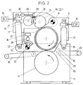
- Fig. 2
- die Seitenansicht der Lackiermaschine mit der Alternative eines verschwenkbaren Lackierzylinders.
- Fig. 1
- the side view of the painting machine described in the case of a pivotable impression cylinder and
- Fig. 2
- the side view of the painting machine with the alternative of a swiveling painting cylinder.
In den beiden Alternativen unterscheiden sich die paarweise vorhandenen Subseitenteile 10 vorrangig in ihrer Form und im Ort ihres am Maschinengestell 11 befindlichen Schwenklagers 12. Zwischen der am Subseitenteil 10 angreifenden Motorspindel 13 und dem Schwenklager 12 ist mit seinem stirnseitigen Lager entweder der Gegendruckzylinder 14 oder der Lackierzylinder 15 angeordnet. Das Schwenklager 16 jedes der beiden stirnseitigen Lagerträger 17 der Lackzuführwalze 18 befindet sich entweder am ortsfesten Maschinengestell 11 oder am seinerseits verschwenkbaren Subseitenteil 10. Die beiden Motorspindeln 13 sind ein besonderer Bestandteil der Anstelleinrichtung 19 für die Pressung zwischen dem einen Mantel 20 aus Gummi aufweisenden Lackierzylinder 15 und dem harten Gegendruckzylinder 14 und die beiden Motorspindeln 21 ebenso ein besonderer Bestandteil der Anstelleinrichtung 22 für die Pressung zwischen dem Lackierzylinder 15 und der Lackzuführwalze 18 des Lackwerkes 23.In the two alternatives, the pair of
Vorteilhafterweise ist an den beiden verschwenkbaren Lagerträgern 17 der Lackzuführwalze 18 das gesamte Lackwerk 23 angebracht, was außer dem Lackwerk 23 auch die Einstelleinrichtung für die auf den Lackierzylinder 15 der Lackiermaschine ausgeübten Preßdrücke vereinfacht und die Wartung der Lackiermaschine erleichtert. Eine besonders kompakte und funktionssichere Bauform des Lackwerks 23 ergibt sich dadurch, daß im Lackwerk 23 die Lackzuführwalze 18 und eine gegen diese gedrückte weitere Lackwalze 24 zur Begrenzung eines Lackvorratssees 25 verwendet sind. Sie werden vorzugsweise mit gegenläufigem Drehsinn und im Bereich des Lackvorratssees 25 in Abwärtsrichtung drehend angetrieben. Im Lackvorratssee 25 sind in horizontaler Ausrichtung untergetaucht ein mit seiner Rakelschneide gegen die Lackzuführwalze 18 gerichteter Lackabstreicher 26 und ein mit seiner Rakelschneide gegen die Lackwalze 24 gerichteter Lackabstreicher 27 angeordnet. Für die beiden Lackabstreicher 26 und 27 ist eine gemeinsame Halteeinrichtung dergestalt vorgesehen, daß sie mittels eines Schwenkarme 28 aufweisenden Tragbalkens 29 von der Lackzuführwalze 18 und der Lackwalze 24 nach oben wegschwenkbar und nach unten zurückschwenkbar sind und die Schwenkarme 28 an einer zu der Lackzuführwalze 18 und der weiteren Lackwalze 24 achsparallelen Welle 30 längsverschiebbar gelagert sind.Advantageously, the
Zur bequemeren Reinigung der Lackiermaschine in Bezug auf einen schnellen Lackwechsel und zur Erleichterung anderer Wartungsarbeiten sind die beiden verschwenkbaren Lagerträger 17 der Lackzuführwalze 18 und die beiden am Maschinengestell 11 oder Subseitenteil 10 und andernends am Lagerträger 17 angelenkten Motorspindeln 21 außer für die Pressung zwischen dem Lackierzylinder 15 und der Lackzuführwalze 18 für die Freilegung des Lackierzylinders 15 eingerichtet. Aus diesem Grunde erhalten die Motorspindeln 21 einen vergrößerten Verstellhub, die Lagerträger 17 eine gestrecktere Form und die Schwenklager 16 einen größeren Abstand von der gemeinsamen Berührungszone des Lackierzylinders 15 und der Lackzuführwalze 18.For more convenient cleaning of the painting machine in relation to a quick paint change and to facilitate other maintenance work, the two pivotable bearing supports 17 of the
Die an den beiden Motorspindeln 13 anstehenden Axialdrücke sind von je einem Drucksensor 31 erfaßbar und von je einem an den Drucksensor 31 angeschlossenen Druckregler 32 auf einen vorwählbaren Konstantwert einregelbar eingerichtet. Damit erfolgt die eigentliche Einstellung der Pressung zwischen dem Lackierzylinder 15 und dem Gegendruckzylinder 14 vollautomatisch und wird einer sich ändernden Quellung im Mantel 20 des Lackierzylinders 15 und einem Nachschliff des Lackierzylinders 15 Rechnung getragen. Entsprechendes gilt für die Einstellung der Pressung zwischen dem Lackierzylinder 15 und der Lackzuführwalze 18, nachdem die an den anderen beiden Motorspindeln 21 anstehenden Axialdrücke von je einem Drucksensor 33 erfaßbar und von je einem an den Drucksensor 33 angeschlossenen Druckregler 34 auf einen vorwählbaren Konstantwert einregelbar eingerichtet sind.The axial pressures applied to the two
Indem die Schwenkstellung des Lackierzylinders 15 oder des Gegendruckzylinders 14 oder der Lackzuführwalze 18 von einem Wegsensor 35 erfaßbar gemacht ist und das Lagesignal des Wegsensors 35 bei eingeregelter Pressung in einem Drehzahlregler 36 für eine zum Gegendruckzylinder 14 konforme Umfangsgeschwindigkeit des Lackierzylinders 15 als Regelgröße verwendet ist, erhalten die beiden Motorspindeln 13 oder die beiden Motorspindeln 21 eine Zusatzfunktion. Selbst bei einem besonders großen Durchmesserbereich des Lackierzylinders 15, der außer einer sich ändernden Quellung im Mantel 20 ein häufiges Nachschleifen zuläßt, gestaltet sich die Drehzahlanpassung damit äußerst präzise und aufwandsarm. Durch die Drehzahlanpassung werden unbenutzte Lackfelder des Lackierzylinders 15 zur Sauberhaltung der Unterseite der mit Abstand aufeinanderfolgenden Werkstücke auf dem Mantel 20 des Lackierzylinders 15 ortsfest gehalten. Dazu gehört, daß die in Ergänzung eingangsseitiger Transportriemen 37 zum Abtransport der Werkstücke vorgesehenen Auslageriemen 38 in ihrem Umlauf taktgleich mit einer Umdrehung des Gegendruckzylinders 14 angetrieben sind.By making the swivel position of the
In der bevorzugten Ausführungsform enthält der Wegsensor 35 einen elektrischen Regelwiderstand eines in seiner Drehbewegung an die Schwenkbewegung des Subseitenteils 10 gekoppelten Potentiometers 39. Damit ergibt sich außer für die betreffende Motorspindel 13 auch für das von ihr erfaßte Subseitenteil 10 eine Zusatzfunktion und wird der bauliche Mehraufwand für das Vorsehen der Drehzahlregelung extrem klein gehalten. Dadurch, daß der dem Subseitenteil 10 zugeordnete Drucksensor 31 auf den Mittelbereich der Werkstücke begrenzt zum Druckregler 32 durchgeschaltet ist, wird die Genauigkeit der Drehzahlanpassung weiter gesteigert.In the preferred embodiment, the displacement sensor contains 35 an electrical variable resistor of a
Mit ihren eingangsseitigen Transportriemen 37 und ihren ausgangsseitigen Auslageriemen 38 ist die beschriebene Lackiermaschine dem speziellen Einsatzbereich des einseitigen Lackierens tafelförmiger Feinbleche angepaßt. Sie läßt sich aber im Rahmen der Erfindung ganz generell zum Lackieren tafel- bis blattförmiger Werkstücke verwenden, also insbesondere auch solcher aus Karton oder Papier. Die Verbesserungen in der Aussparlackierung sind beispielsweise dann von größerer Bedeutung, wenn an Faltschachtelzuschnitten in der Lackierung präzise Freiplätze für Klebstoff vorgesehen werden.With its input-
Claims (9)
Applications Claiming Priority (4)
| Application Number | Priority Date | Filing Date | Title |
|---|---|---|---|
| DE19513131 | 1995-04-07 | ||
| DE19513131 | 1995-04-07 | ||
| DE19515823 | 1995-04-29 | ||
| DE19515823A DE19515823C1 (en) | 1995-04-07 | 1995-04-29 | Painting machine |
Publications (2)
| Publication Number | Publication Date |
|---|---|
| EP0736330A2 true EP0736330A2 (en) | 1996-10-09 |
| EP0736330A3 EP0736330A3 (en) | 1997-07-09 |
Family
ID=26014218
Family Applications (1)
| Application Number | Title | Priority Date | Filing Date |
|---|---|---|---|
| EP96105164A Withdrawn EP0736330A3 (en) | 1995-04-07 | 1996-03-30 | Coating apparatus |
Country Status (3)
| Country | Link |
|---|---|
| US (1) | US5683512A (en) |
| EP (1) | EP0736330A3 (en) |
| JP (1) | JPH08323258A (en) |
Cited By (1)
| Publication number | Priority date | Publication date | Assignee | Title |
|---|---|---|---|---|
| CN103182357A (en) * | 2011-12-30 | 2013-07-03 | 北京星和众工设备技术股份有限公司 | Roller coater coating thickness automatic adjusting method |
Families Citing this family (7)
| Publication number | Priority date | Publication date | Assignee | Title |
|---|---|---|---|---|
| NL1022048C2 (en) * | 2002-12-02 | 2004-06-03 | Mps Holding B V | Printing module as well as a printing machine provided with such a printing module. |
| JP4642360B2 (en) * | 2004-02-12 | 2011-03-02 | キヤノン株式会社 | Liquid applicator, recording device |
| CN101484253B (en) * | 2006-07-05 | 2011-03-09 | 菲奇工程技术有限公司 | Roll support device, roll coating head using the same, roll coater, and coating method |
| CN103157576B (en) * | 2013-03-08 | 2016-08-24 | 江苏华宇印涂设备集团有限公司 | Coating machine eliminates the device in gap |
| WO2016000749A1 (en) * | 2014-06-30 | 2016-01-07 | Hewlett-Packard Indigo B.V. | Contact control of print blanket to impression drum |
| US9833810B2 (en) * | 2014-07-25 | 2017-12-05 | Basf Corporation | Apparatus and process for face painting substrates with PGM and base metal solutions |
| JP7532995B2 (en) * | 2020-03-13 | 2024-08-14 | 株式会社リコー | Coating device and image forming system |
Family Cites Families (14)
| Publication number | Priority date | Publication date | Assignee | Title |
|---|---|---|---|---|
| DE615299C (en) * | 1934-01-24 | 1935-07-02 | Radebeuler Maschinenfabrik Aug | Device on mass application machines for reading and setting the thickness of the order |
| DE2343431C3 (en) * | 1973-08-29 | 1979-04-19 | Achenbach Buschluetten Gmbh, 5910 Kreuztal | Device for the continuous coating of strip-shaped material to be treated |
| US4495886A (en) * | 1983-09-26 | 1985-01-29 | The Black Clawson Company | Precision roll coater |
| DE3429049A1 (en) * | 1984-08-07 | 1986-02-20 | Robert Bürkle GmbH & Co, 7290 Freudenstadt | Device for coating planar workpieces with materials which are capable of flowing |
| US4704296A (en) * | 1984-09-28 | 1987-11-03 | Magna-Graphics Corporation | Web coating method and apparatus |
| DE3442662A1 (en) * | 1984-11-23 | 1986-06-05 | Albert-Frankenthal Ag, 6710 Frankenthal | INK |
| US4610216A (en) * | 1985-04-02 | 1986-09-09 | Gustav Paulsen | Paper coloring apparatus |
| ATE88135T1 (en) * | 1986-10-14 | 1993-04-15 | Komori Printing Mach | VARNISHING DEVICE FOR PRINTED SHEETS. |
| US5178678A (en) * | 1989-06-13 | 1993-01-12 | Dahlgren International, Inc. | Retractable coater assembly including a coating blanket cylinder |
| DE3926088C1 (en) * | 1989-08-07 | 1990-10-31 | Heidelberger Druckmasch Ag | Rotary printing machine with device for the supply and removal of the coating / blanket cylinder to the printing cylinder and / or metering / plate cylinder |
| US5272975A (en) * | 1990-04-25 | 1993-12-28 | Man Roland Druckmaschinen Ag | Throw-on/throw-off device for a blanket cylinder with a printing speed dependent control system for a sheet-fed offset press |
| FI88063C (en) * | 1990-10-12 | 1993-03-25 | Valmet Paper Machinery Inc | ANORDING FOR THE DOSERING OF BODY MACHINES AND BODIES |
| JP3014771B2 (en) * | 1990-12-27 | 2000-02-28 | 川崎製鉄株式会社 | Method and apparatus for controlling film thickness by roll coater |
| NO175293C (en) * | 1992-07-08 | 1994-10-05 | Gp Tinter As | paper coloring |
-
1996
- 1996-03-30 EP EP96105164A patent/EP0736330A3/en not_active Withdrawn
- 1996-04-05 JP JP8084081A patent/JPH08323258A/en active Pending
- 1996-04-08 US US08/629,247 patent/US5683512A/en not_active Expired - Fee Related
Cited By (2)
| Publication number | Priority date | Publication date | Assignee | Title |
|---|---|---|---|---|
| CN103182357A (en) * | 2011-12-30 | 2013-07-03 | 北京星和众工设备技术股份有限公司 | Roller coater coating thickness automatic adjusting method |
| CN103182357B (en) * | 2011-12-30 | 2015-11-04 | 北京星和众工设备技术股份有限公司 | The self-adjusting method of roller coater coating thickness |
Also Published As
| Publication number | Publication date |
|---|---|
| US5683512A (en) | 1997-11-04 |
| JPH08323258A (en) | 1996-12-10 |
| EP0736330A3 (en) | 1997-07-09 |
Similar Documents
| Publication | Publication Date | Title |
|---|---|---|
| EP0234456B1 (en) | Supplementary printing unit | |
| DE69905305T2 (en) | edge banding | |
| EP0010237A1 (en) | Combined dampening and inking device for offset-printing machines and method for inking and dampening an offset-printing plate | |
| DE3032001C2 (en) | Machine for the production of single-sided corrugated cardboard with automatic control of the roller gap | |
| WO2011104221A1 (en) | Device for machining the narrow surfaces of preferably board-shaped workpieces | |
| DE2950881C2 (en) | Control device for the processing pressure on lapping, honing and wear machines | |
| DE60221326T2 (en) | Printing device, in particular flexographic printing machine | |
| EP0826501B2 (en) | Device for adjusting an inking or damping roller in a printing machine | |
| DE3424258C2 (en) | Machine for edge grinding of glass panes | |
| DE3143781A1 (en) | DEVICE FOR AUTOMATICALLY CONTROLLING A QUANTITY OF LIQUID FEEDED IN A PRESS PRESS | |
| DE4335282C2 (en) | Method for controlling the sequence of a driven inking roller in relation to a driven forme cylinder in the printing unit of an offset rotary printing machine and a correspondingly controlled printing unit | |
| DE69614214T2 (en) | Cleaning device for rollers | |
| EP0736331A2 (en) | Device for adjusting the pressure applied on the coating roller of a coating apparatus | |
| DE2831763A1 (en) | BOOKBINDING MACHINE | |
| DE3141990A1 (en) | INK BOX FOR A PRINT PRESS | |
| DE19515823C1 (en) | Painting machine | |
| DE3932232A1 (en) | Squeegee device | |
| DE2549003A1 (en) | PRINTING DEVICE FOR DOCUMENTS | |
| DE19515824C1 (en) | Adjustment device for pressing pressures exerted on the painting cylinder of a painting machine | |
| DE102010061644A1 (en) | Creping blade system has creping blade which has rear area and front area serving as working edge, where rear area of creping blade is mounted in bag sliding in direction of rotating cylinder | |
| DE2335575B2 (en) | ||
| DE3226573C2 (en) | ||
| DE3445739A1 (en) | DEVICE FOR APPLYING A PASTE TO A BATTERY GRID | |
| EP2123468B1 (en) | Gluing device | |
| DE4108147C1 (en) | Grinding machine for deburring and finishing flat work - has switches operating electronic circuit controlling proportional valve setting pressure in lifting hose |
Legal Events
| Date | Code | Title | Description |
|---|---|---|---|
| PUAI | Public reference made under article 153(3) epc to a published international application that has entered the european phase |
Free format text: ORIGINAL CODE: 0009012 |
|
| AK | Designated contracting states |
Kind code of ref document: A2 Designated state(s): DE ES GB IT |
|
| PUAL | Search report despatched |
Free format text: ORIGINAL CODE: 0009013 |
|
| AK | Designated contracting states |
Kind code of ref document: A3 Designated state(s): DE ES GB IT |
|
| 17P | Request for examination filed |
Effective date: 19971222 |
|
| 17Q | First examination report despatched |
Effective date: 19990622 |
|
| GRAG | Despatch of communication of intention to grant |
Free format text: ORIGINAL CODE: EPIDOS AGRA |
|
| GRAG | Despatch of communication of intention to grant |
Free format text: ORIGINAL CODE: EPIDOS AGRA |
|
| GRAG | Despatch of communication of intention to grant |
Free format text: ORIGINAL CODE: EPIDOS AGRA |
|
| GRAH | Despatch of communication of intention to grant a patent |
Free format text: ORIGINAL CODE: EPIDOS IGRA |
|
| STAA | Information on the status of an ep patent application or granted ep patent |
Free format text: STATUS: THE APPLICATION IS DEEMED TO BE WITHDRAWN |
|
| 18D | Application deemed to be withdrawn |
Effective date: 20030114 |