EP0736330A2 - Machine d'enduction - Google Patents
Machine d'enduction Download PDFInfo
- Publication number
- EP0736330A2 EP0736330A2 EP96105164A EP96105164A EP0736330A2 EP 0736330 A2 EP0736330 A2 EP 0736330A2 EP 96105164 A EP96105164 A EP 96105164A EP 96105164 A EP96105164 A EP 96105164A EP 0736330 A2 EP0736330 A2 EP 0736330A2
- Authority
- EP
- European Patent Office
- Prior art keywords
- painting
- cylinder
- coating
- pressure
- machine according
- Prior art date
- Legal status (The legal status is an assumption and is not a legal conclusion. Google has not performed a legal analysis and makes no representation as to the accuracy of the status listed.)
- Withdrawn
Links
Images
Classifications
-
- B—PERFORMING OPERATIONS; TRANSPORTING
- B05—SPRAYING OR ATOMISING IN GENERAL; APPLYING FLUENT MATERIALS TO SURFACES, IN GENERAL
- B05C—APPARATUS FOR APPLYING FLUENT MATERIALS TO SURFACES, IN GENERAL
- B05C1/00—Apparatus in which liquid or other fluent material is applied to the surface of the work by contact with a member carrying the liquid or other fluent material, e.g. a porous member loaded with a liquid to be applied as a coating
- B05C1/04—Apparatus in which liquid or other fluent material is applied to the surface of the work by contact with a member carrying the liquid or other fluent material, e.g. a porous member loaded with a liquid to be applied as a coating for applying liquid or other fluent material to work of indefinite length
- B05C1/08—Apparatus in which liquid or other fluent material is applied to the surface of the work by contact with a member carrying the liquid or other fluent material, e.g. a porous member loaded with a liquid to be applied as a coating for applying liquid or other fluent material to work of indefinite length using a roller or other rotating member which contacts the work along a generating line
- B05C1/0873—Controlling means responsive to conditions of the liquid or other fluent material, of the ambient medium, of the roller or of the work
-
- B—PERFORMING OPERATIONS; TRANSPORTING
- B05—SPRAYING OR ATOMISING IN GENERAL; APPLYING FLUENT MATERIALS TO SURFACES, IN GENERAL
- B05C—APPARATUS FOR APPLYING FLUENT MATERIALS TO SURFACES, IN GENERAL
- B05C1/00—Apparatus in which liquid or other fluent material is applied to the surface of the work by contact with a member carrying the liquid or other fluent material, e.g. a porous member loaded with a liquid to be applied as a coating
- B05C1/04—Apparatus in which liquid or other fluent material is applied to the surface of the work by contact with a member carrying the liquid or other fluent material, e.g. a porous member loaded with a liquid to be applied as a coating for applying liquid or other fluent material to work of indefinite length
- B05C1/08—Apparatus in which liquid or other fluent material is applied to the surface of the work by contact with a member carrying the liquid or other fluent material, e.g. a porous member loaded with a liquid to be applied as a coating for applying liquid or other fluent material to work of indefinite length using a roller or other rotating member which contacts the work along a generating line
- B05C1/0821—Apparatus in which liquid or other fluent material is applied to the surface of the work by contact with a member carrying the liquid or other fluent material, e.g. a porous member loaded with a liquid to be applied as a coating for applying liquid or other fluent material to work of indefinite length using a roller or other rotating member which contacts the work along a generating line characterised by driving means for rollers or work
-
- B—PERFORMING OPERATIONS; TRANSPORTING
- B05—SPRAYING OR ATOMISING IN GENERAL; APPLYING FLUENT MATERIALS TO SURFACES, IN GENERAL
- B05C—APPARATUS FOR APPLYING FLUENT MATERIALS TO SURFACES, IN GENERAL
- B05C1/00—Apparatus in which liquid or other fluent material is applied to the surface of the work by contact with a member carrying the liquid or other fluent material, e.g. a porous member loaded with a liquid to be applied as a coating
- B05C1/04—Apparatus in which liquid or other fluent material is applied to the surface of the work by contact with a member carrying the liquid or other fluent material, e.g. a porous member loaded with a liquid to be applied as a coating for applying liquid or other fluent material to work of indefinite length
- B05C1/08—Apparatus in which liquid or other fluent material is applied to the surface of the work by contact with a member carrying the liquid or other fluent material, e.g. a porous member loaded with a liquid to be applied as a coating for applying liquid or other fluent material to work of indefinite length using a roller or other rotating member which contacts the work along a generating line
- B05C1/0826—Apparatus in which liquid or other fluent material is applied to the surface of the work by contact with a member carrying the liquid or other fluent material, e.g. a porous member loaded with a liquid to be applied as a coating for applying liquid or other fluent material to work of indefinite length using a roller or other rotating member which contacts the work along a generating line the work being a web or sheets
- B05C1/083—Apparatus in which liquid or other fluent material is applied to the surface of the work by contact with a member carrying the liquid or other fluent material, e.g. a porous member loaded with a liquid to be applied as a coating for applying liquid or other fluent material to work of indefinite length using a roller or other rotating member which contacts the work along a generating line the work being a web or sheets being passed between the coating roller and one or more backing rollers
-
- B—PERFORMING OPERATIONS; TRANSPORTING
- B05—SPRAYING OR ATOMISING IN GENERAL; APPLYING FLUENT MATERIALS TO SURFACES, IN GENERAL
- B05C—APPARATUS FOR APPLYING FLUENT MATERIALS TO SURFACES, IN GENERAL
- B05C1/00—Apparatus in which liquid or other fluent material is applied to the surface of the work by contact with a member carrying the liquid or other fluent material, e.g. a porous member loaded with a liquid to be applied as a coating
- B05C1/04—Apparatus in which liquid or other fluent material is applied to the surface of the work by contact with a member carrying the liquid or other fluent material, e.g. a porous member loaded with a liquid to be applied as a coating for applying liquid or other fluent material to work of indefinite length
- B05C1/08—Apparatus in which liquid or other fluent material is applied to the surface of the work by contact with a member carrying the liquid or other fluent material, e.g. a porous member loaded with a liquid to be applied as a coating for applying liquid or other fluent material to work of indefinite length using a roller or other rotating member which contacts the work along a generating line
- B05C1/0873—Controlling means responsive to conditions of the liquid or other fluent material, of the ambient medium, of the roller or of the work
- B05C1/0878—Controlling means responsive to conditions of the liquid or other fluent material, of the ambient medium, of the roller or of the work responsive to the pressure applied between two rollers, e.g. between the coating roller and a backing roller or between the coating roller and a dosing roller
Definitions
- the invention relates to a painting machine in which the sheet-like to sheet-shaped workpieces are moved between a painting cylinder with a jacket made of rubber or another elastic material and a hard impression cylinder, the change in its peripheral speed caused by swelling or regrinding of the painting cylinder can be compensated for by a speed controller is and an adjusting device is provided for the pressure between the painting cylinder and the impression cylinder.
- Such machines are used, for example, in the manufacture of beverage cans, glass lids or crown caps, where the printing is preceded by an internal coating and an external coating and a protective coating follows.
- There are special requirements placed on the paint so that it can be used for later punching and deep drawing does not burst.
- previous painting machines poured paint over the workpieces
- modern painting machines aim to use paint as economically as possible.
- painting cylinders with precisely positioned cutouts are often used for recess painting.
- painting cylinders for full painting have the advantage that they can be reground many times and used for a correspondingly longer time.
- the change in the peripheral speed of the coating cylinder caused by the reduction in diameter must then be compensated for.
- a need for compensation for the peripheral speed of the painting cylinder exists to a lesser extent also due to changing swelling in the jacket of the painting cylinder.
- the precise setting of the pressure between the coating cylinder and the impression cylinder is a prerequisite for achieving an extremely thin and at the same time extremely uniform coating application.
- a machine of the type mentioned at the beginning is already known from the market due to its own manufacture.
- the painting cylinder for full painting is driven by a compressed air-operated slip clutch, which enables sensitive regulation of the peripheral speed during the run.
- This regulation requires operator participation.
- An electrical control device is installed for the recess painting, which monitors the rigidly coupled cylinder setting. Including uncoupling for setup purposes, a total of three operating states can be set with a switch lever.
- the adjustment of the coating cylinder and the coating feed roller, the switching on and off of all the rollers, their parallel positioning and the metering of the coating application are central on the operating side the machine summarized using spindles provided with a handwheel.
- the coating cylinder and the coating feed roller can be fixed to the machine frame without play. However, this does not preclude locally uneven contact pressures, including possible operating errors, across the surface line of the painting cylinder with the high level of safety that has now been desired.
- the invention has for its object to reliably avoid irregularities in the contact pressures of the painting cylinder with a simple means in a painting machine of the type mentioned in order to realize an extremely thin and therefore particularly economical paint application, and one for the change in its peripheral speed caused by swelling or regrinding of the painting cylinder to create automatic compensation.
- the two end bearings of the painting cylinder or the impression cylinder are each arranged in a pivotally mounted on the machine frame side part, for pivoting each side part, a motor spindle articulated with one end to the machine frame and with its other end to the side part , the axial pressures applied to the two motor spindles can be detected by a pressure sensor and adjusted to a preselectable constant value by a pressure controller connected to the pressure sensor, and the swivel position of one of the two sub-side parts detected by a displacement sensor is used as a control variable for the speed controller.
- the manual is therefore reduced on the painting machine Operation for setting the pressure on the mutual preselection of a setpoint.
- the actual setting is then carried out fully automatically and at a higher speed. Any trend towards a deviating actual value is counteracted immediately during operation.
- the motor spindles on the two sides of the machine are independent of one another, this ensures that the contact pressure between the coating cylinder and the impression cylinder is the same on both sides.
- the motor spindles allow a very sensitive pressure setting and preclude ringing compared to a hydraulic or pneumatic drive. In addition to a gain in quality and safety, there is a reduction in operating effort and a space saving due to the elimination of spindles provided with a handwheel.
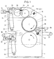
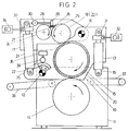
- the pair of sub-side parts 10 differ primarily in their shape and in the location of their pivot bearing 12 located on the machine frame 11. Between the motor spindle 13 engaging the sub-side part 10 and the pivot bearing 12, with its end bearing, either the counter-pressure cylinder 14 or the painting cylinder 15 arranged.
- the pivot bearing 16 of each of the two end bearing supports 17 of the paint supply roller 18 is located either on the stationary machine frame 11 or on the pivotable lower part 10.
- the two motor spindles 13 are a special component of the adjusting device 19 for the pressure between the coating cylinder 15 having a rubber jacket 20 and the hard counter-pressure cylinder 14 and the two motor spindles 21 are also a special component of the adjusting device 22 for the pressing between the coating cylinder 15 and the coating feed roller 18 of the coating unit 23.
- the entire coating unit 23 is attached to the two pivotable bearing supports 17 of the coating feed roller 18, which, in addition to the coating unit 23, also simplifies the setting device for the pressing pressures exerted on the coating cylinder 15 of the coating machine and simplifies maintenance of the coating machine.
- a particularly compact and functionally reliable design of the coating unit 23 results from the fact that in the coating unit 23 the coating feed roller 18 and a further coating roller 24 pressed against it are used to limit a coating reservoir 25. They are preferably in the opposite direction and in the region of the lacquer reservoir 25 in the downward direction driven rotating.
- a paint scraper 26 directed with its doctor blade against the paint supply roller 18 and a paint scraper 27 with its doctor blade against the paint roller 24 are immersed in a horizontal orientation.
- a common holding device is provided in such a way that they can be pivoted away from the paint feed roller 18 and the paint roller 24 by means of a support arm 29 having pivot arms 28 and can be pivoted back down and the pivot arms 28 on one to the paint feed roller 18 and the further coating roller 24 axially parallel shaft 30 are mounted for longitudinal displacement.
- the two pivotable bearing supports 17 of the paint supply roller 18 and the two motor spindles 21 articulated on the machine frame 11 or side part 10 and on the other side on the bearing support 17 are except for the pressure between the painting cylinder 15 and the paint feed roller 18 are set up to expose the painting cylinder 15.
- the motor spindles 21 have an increased adjustment stroke
- the bearing supports 17 have a more elongated shape
- the pivot bearings 16 have a greater distance from the common contact zone of the coating cylinder 15 and the coating feed roller 18.
- the axial pressures applied to the two motor spindles 13 can be detected by a pressure sensor 31 each and can be adjusted to a preselectable constant value by a pressure regulator 32 connected to the pressure sensor 31. So that the actual setting of the pressure between the painting cylinder 15 and the impression cylinder takes place 14 fully automatically and a changing swelling in the jacket 20 of the painting cylinder 15 and regrinding of the painting cylinder 15 is taken into account.
- the two motor spindles 13 or the two motor spindles 21 have an additional function. Even with a particularly large diameter range of the coating cylinder 15, which, in addition to changing swelling in the casing 20, permits frequent regrinding, the speed adjustment is thus extremely precise and requires little effort.
- unused paint fields of the painting cylinder 15 are kept stationary on the jacket 20 of the painting cylinder 15 in order to keep the underside of the workpieces, which follow one another at a distance, clean.
- the displacement sensor contains 35 an electrical variable resistor of a potentiometer 39 coupled in its rotational movement to the pivoting movement of the side part 10.
- this also results in an additional function for the side part 10 it detects and the additional construction effort for providing the speed control is kept extremely small .
- the pressure sensor 31 assigned to the sub-side part 10 is limited to the central region of the workpieces to the pressure regulator 32, the accuracy of the speed adjustment is further increased.
- the painting machine described With its input-side transport belts 37 and its output-side delivery belts 38, the painting machine described is adapted to the special area of application of one-sided painting of sheet-like sheet metal. However, within the scope of the invention, it can be used quite generally for painting panel-to-sheet workpieces, in particular also those made of cardboard or paper. The improvements in the recess painting are of greater importance, for example, if precise free spaces for adhesive are provided on folding box blanks in the painting.
Landscapes
- Coating Apparatus (AREA)
- Manufacture Of Motors, Generators (AREA)
Applications Claiming Priority (4)
| Application Number | Priority Date | Filing Date | Title |
|---|---|---|---|
| DE19513131 | 1995-04-07 | ||
| DE19513131 | 1995-04-07 | ||
| DE19515823A DE19515823C1 (de) | 1995-04-07 | 1995-04-29 | Lackiermaschine |
| DE19515823 | 1995-04-29 |
Publications (2)
| Publication Number | Publication Date |
|---|---|
| EP0736330A2 true EP0736330A2 (fr) | 1996-10-09 |
| EP0736330A3 EP0736330A3 (fr) | 1997-07-09 |
Family
ID=26014218
Family Applications (1)
| Application Number | Title | Priority Date | Filing Date |
|---|---|---|---|
| EP96105164A Withdrawn EP0736330A3 (fr) | 1995-04-07 | 1996-03-30 | Machine d'enduction |
Country Status (3)
| Country | Link |
|---|---|
| US (1) | US5683512A (fr) |
| EP (1) | EP0736330A3 (fr) |
| JP (1) | JPH08323258A (fr) |
Cited By (1)
| Publication number | Priority date | Publication date | Assignee | Title |
|---|---|---|---|---|
| CN103182357A (zh) * | 2011-12-30 | 2013-07-03 | 北京星和众工设备技术股份有限公司 | 辊涂机涂层厚度自动调整的方法 |
Families Citing this family (7)
| Publication number | Priority date | Publication date | Assignee | Title |
|---|---|---|---|---|
| NL1022048C2 (nl) * | 2002-12-02 | 2004-06-03 | Mps Holding B V | Drukmodule alsmede een drukmachine voorzien van een dergelijke drukmodule. |
| JP4642360B2 (ja) * | 2004-02-12 | 2011-03-02 | キヤノン株式会社 | 液体塗布装置、記録装置 |
| US8353258B2 (en) * | 2006-07-05 | 2013-01-15 | Michael Arthur Fitch | Roll support and roll coating apparatus |
| CN103157576B (zh) * | 2013-03-08 | 2016-08-24 | 江苏华宇印涂设备集团有限公司 | 涂料机消除间隙的装置 |
| US10078294B2 (en) * | 2014-06-30 | 2018-09-18 | Hp Indigo B.V. | Contact control of print blanket to impression drum |
| US9833810B2 (en) * | 2014-07-25 | 2017-12-05 | Basf Corporation | Apparatus and process for face painting substrates with PGM and base metal solutions |
| JP7532995B2 (ja) * | 2020-03-13 | 2024-08-14 | 株式会社リコー | 塗布装置、及び、画像形成システム |
Family Cites Families (14)
| Publication number | Priority date | Publication date | Assignee | Title |
|---|---|---|---|---|
| DE615299C (de) * | 1934-01-24 | 1935-07-02 | Radebeuler Maschinenfabrik Aug | Vorrichtung an Masseauftragmaschinen zum Ablesen und Einstellen der Dicke des Auftrages |
| DE2343431C3 (de) * | 1973-08-29 | 1979-04-19 | Achenbach Buschluetten Gmbh, 5910 Kreuztal | Vorrichtung zum kontinuierlichen Beschichten von bandförmigem Behandlungsgut |
| US4495886A (en) * | 1983-09-26 | 1985-01-29 | The Black Clawson Company | Precision roll coater |
| DE3429049A1 (de) * | 1984-08-07 | 1986-02-20 | Robert Bürkle GmbH & Co, 7290 Freudenstadt | Vorrichtung zur beschichtung planer werkstuecke mit fliessfaehigen werkstoffen |
| US4704296A (en) * | 1984-09-28 | 1987-11-03 | Magna-Graphics Corporation | Web coating method and apparatus |
| DE3442662A1 (de) * | 1984-11-23 | 1986-06-05 | Albert-Frankenthal Ag, 6710 Frankenthal | Farbwerk |
| US4610216A (en) * | 1985-04-02 | 1986-09-09 | Gustav Paulsen | Paper coloring apparatus |
| EP0264460B1 (fr) * | 1986-10-14 | 1993-04-14 | Komori Corporation | Dispositif de vernissage pour feuilles imprimées |
| US5178678A (en) * | 1989-06-13 | 1993-01-12 | Dahlgren International, Inc. | Retractable coater assembly including a coating blanket cylinder |
| DE3926088C1 (de) * | 1989-08-07 | 1990-10-31 | Heidelberger Druckmasch Ag | Rotationsdruckmaschine mit Einrichtung zur Zu- und Abstellung des Lackier-/Gummituchzylinders zum Druckzylinder und/oder Dosier-/Plattenzylinder |
| US5272975A (en) * | 1990-04-25 | 1993-12-28 | Man Roland Druckmaschinen Ag | Throw-on/throw-off device for a blanket cylinder with a printing speed dependent control system for a sheet-fed offset press |
| FI88063C (fi) * | 1990-10-12 | 1993-03-25 | Valmet Paper Machinery Inc | Anordning foer dosering av bestrykningsmedel pao ett roerligt underlag |
| JP3014771B2 (ja) * | 1990-12-27 | 2000-02-28 | 川崎製鉄株式会社 | ロールコーターによる塗膜厚制御方法および装置 |
| NO175293C (no) * | 1992-07-08 | 1994-10-05 | Gp Tinter As | Papirinnfargingsapparat |
-
1996
- 1996-03-30 EP EP96105164A patent/EP0736330A3/fr not_active Withdrawn
- 1996-04-05 JP JP8084081A patent/JPH08323258A/ja active Pending
- 1996-04-08 US US08/629,247 patent/US5683512A/en not_active Expired - Fee Related
Cited By (2)
| Publication number | Priority date | Publication date | Assignee | Title |
|---|---|---|---|---|
| CN103182357A (zh) * | 2011-12-30 | 2013-07-03 | 北京星和众工设备技术股份有限公司 | 辊涂机涂层厚度自动调整的方法 |
| CN103182357B (zh) * | 2011-12-30 | 2015-11-04 | 北京星和众工设备技术股份有限公司 | 辊涂机涂层厚度自动调整的方法 |
Also Published As
| Publication number | Publication date |
|---|---|
| JPH08323258A (ja) | 1996-12-10 |
| US5683512A (en) | 1997-11-04 |
| EP0736330A3 (fr) | 1997-07-09 |
Similar Documents
| Publication | Publication Date | Title |
|---|---|---|
| DE69905305T2 (de) | Kantenleimgerät | |
| EP0234456B1 (fr) | Dispositif d'impression complémentaire | |
| EP0010237A1 (fr) | Dispositif combiné de mouillage et d'encrage pour une machine à imprimer offset et procédé pour encrer et mouiller un cliché d'impression offset | |
| DE3032001C2 (de) | Maschine zur Herstellung von Eindeckenwellpappe mit automatischer Steuerung des Walzenspaltes | |
| WO2011104221A1 (fr) | Dispositif pour l'usinage des chants de pièces préférentiellement de forme plate | |
| DE2950881C2 (de) | Steuereinrichtung für den Bearbeitungsdruck an Läpp-, Hon- und Schleißmaschinen | |
| DE60221326T2 (de) | Druckvorrichtung, insbesondere flexographische Druckmaschine | |
| EP0826501B2 (fr) | Dispositif utilisé pour ajuster un rouleau d'encrage ou de mouillage dans une machine à imprimer | |
| EP0736330A2 (fr) | Machine d'enduction | |
| DE3424258C2 (de) | Maschine zum Kantenschleifen von Glasscheiben | |
| DE3143781A1 (de) | Vorrichtung zum automatischen steuern einer einer druckpresse zugefuehrten fluessigkeitsmenge | |
| DE4335282C2 (de) | Verfahren zur Steuerung des Ablaufs einer angetriebenen Farbauftragwalze in Bezug auf einen angetriebenen Formzylinder im Druckwerk einer Offsetrotationsdruckmaschine sowie ein entsprechend gesteuertes Druckwerk | |
| DE69614214T2 (de) | Reinigungsvorrichtung für Walzen | |
| EP0736331A2 (fr) | Dispositif de réglage de la pression exercée sur le rouleau enducteur d'une machine d'enduction | |
| DE2831763A1 (de) | Buchbindemaschine | |
| DE3141990A1 (de) | Farbkasten fuer eine druckpresse | |
| DE19515823C1 (de) | Lackiermaschine | |
| DE3932232A1 (de) | Rakelvorrichtung | |
| DE2549003A1 (de) | Druckeinrichtung fuer schriftstuecke | |
| DE19515824C1 (de) | Einstelleinrichtung für auf den Lackierzylinder einer Lackiermaschine ausgeübte Preßdrücke | |
| DE102010061644A1 (de) | Kreppschabersystem | |
| DE2335575B2 (fr) | ||
| DE3226573C2 (fr) | ||
| DE3445739A1 (de) | Vorrichtung zum aufbringen einer paste auf batteriegitter | |
| EP2123468B1 (fr) | Dispositif d'encollage |
Legal Events
| Date | Code | Title | Description |
|---|---|---|---|
| PUAI | Public reference made under article 153(3) epc to a published international application that has entered the european phase |
Free format text: ORIGINAL CODE: 0009012 |
|
| AK | Designated contracting states |
Kind code of ref document: A2 Designated state(s): DE ES GB IT |
|
| PUAL | Search report despatched |
Free format text: ORIGINAL CODE: 0009013 |
|
| AK | Designated contracting states |
Kind code of ref document: A3 Designated state(s): DE ES GB IT |
|
| 17P | Request for examination filed |
Effective date: 19971222 |
|
| 17Q | First examination report despatched |
Effective date: 19990622 |
|
| GRAG | Despatch of communication of intention to grant |
Free format text: ORIGINAL CODE: EPIDOS AGRA |
|
| GRAG | Despatch of communication of intention to grant |
Free format text: ORIGINAL CODE: EPIDOS AGRA |
|
| GRAG | Despatch of communication of intention to grant |
Free format text: ORIGINAL CODE: EPIDOS AGRA |
|
| GRAH | Despatch of communication of intention to grant a patent |
Free format text: ORIGINAL CODE: EPIDOS IGRA |
|
| STAA | Information on the status of an ep patent application or granted ep patent |
Free format text: STATUS: THE APPLICATION IS DEEMED TO BE WITHDRAWN |
|
| 18D | Application deemed to be withdrawn |
Effective date: 20030114 |