EP0736436A1 - Schienenfahrzeug - Google Patents
Schienenfahrzeug Download PDFInfo
- Publication number
- EP0736436A1 EP0736436A1 EP96105194A EP96105194A EP0736436A1 EP 0736436 A1 EP0736436 A1 EP 0736436A1 EP 96105194 A EP96105194 A EP 96105194A EP 96105194 A EP96105194 A EP 96105194A EP 0736436 A1 EP0736436 A1 EP 0736436A1
- Authority
- EP
- European Patent Office
- Prior art keywords
- rail vehicle
- profiles
- vehicle according
- longitudinal
- support
- Prior art date
- Legal status (The legal status is an assumption and is not a legal conclusion. Google has not performed a legal analysis and makes no representation as to the accuracy of the status listed.)
- Granted
Links
- 238000005253 cladding Methods 0.000 claims abstract description 16
- 239000000853 adhesive Substances 0.000 claims abstract description 5
- 230000001070 adhesive effect Effects 0.000 claims abstract description 5
- 239000013013 elastic material Substances 0.000 claims description 3
- 229920001971 elastomer Polymers 0.000 claims description 3
- 239000002184 metal Substances 0.000 description 4
- 238000009434 installation Methods 0.000 description 2
- 239000004033 plastic Substances 0.000 description 2
- 239000002023 wood Substances 0.000 description 2
- 206010067482 No adverse event Diseases 0.000 description 1
- 229910000831 Steel Inorganic materials 0.000 description 1
- 238000010276 construction Methods 0.000 description 1
- 230000001419 dependent effect Effects 0.000 description 1
- 230000002349 favourable effect Effects 0.000 description 1
- 239000011521 glass Substances 0.000 description 1
- 238000012423 maintenance Methods 0.000 description 1
- 238000004519 manufacturing process Methods 0.000 description 1
- 239000000463 material Substances 0.000 description 1
- 229920002379 silicone rubber Polymers 0.000 description 1
- 239000004945 silicone rubber Substances 0.000 description 1
- 239000007787 solid Substances 0.000 description 1
- 239000010959 steel Substances 0.000 description 1
- 230000000007 visual effect Effects 0.000 description 1
Images
Classifications
-
- B—PERFORMING OPERATIONS; TRANSPORTING
- B61—RAILWAYS
- B61D—BODY DETAILS OR KINDS OF RAILWAY VEHICLES
- B61D17/00—Construction details of vehicle bodies
- B61D17/04—Construction details of vehicle bodies with bodies of metal; with composite, e.g. metal and wood body structures
- B61D17/08—Sides
-
- B—PERFORMING OPERATIONS; TRANSPORTING
- B61—RAILWAYS
- B61D—BODY DETAILS OR KINDS OF RAILWAY VEHICLES
- B61D17/00—Construction details of vehicle bodies
- B61D17/04—Construction details of vehicle bodies with bodies of metal; with composite, e.g. metal and wood body structures
- B61D17/043—Construction details of vehicle bodies with bodies of metal; with composite, e.g. metal and wood body structures connections between superstructure sub-units
Definitions
- the invention relates to a rail vehicle with a car body with side walls, which have a supporting profile that absorbs vertical forces and cooperate with this, horizontally arranged longitudinal profiles, which is provided on the outside and on the inside with a panel, in which panel windows are arranged, which are bordered by profiles.
- Rail vehicles in particular for the transport of people, usually have a car body which is placed on a frame and has side walls made of sheet steel or light metal.
- support profiles are often provided, which are connected to the wall plate, with corresponding cutouts being made in the side walls into which windows, including frames and are inserted, for windows that may be provided.
- the car body lighter with the same torsional stiffness and instead to provide a framework instead of solid side walls made of sheet metal, which serves as a supporting structure for a cladding.
- the cladding can consist of sheets of thin sheet metal or wood or, in view of low maintenance requirements, of plastic, which are each connected to the framework, for example by means of screws.
- a rail vehicle designed in this way is characterized in that the support profiles are arranged obliquely to the horizontal and are each connected to associated longitudinal profiles which have at least one recess, in each of which a support profile engages, and that the longitudinal profile serves to fasten the cladding.
- the outer cladding is fastened to the longitudinal profiles by means of an adhesive connection. This also enables the individual elements of the outer cladding to be fitted flush, i.e., butt to butt.
- this provides the possibility of providing ready-made individual elements, that is to say, for example already already finished, in the final state for the outer cladding for installation, since the assembly work still to be carried out has no adverse effects on this.
- the inner lining which according to a further preferred embodiment of the invention is held non-positively and positively by the longitudinal profile, so that no disturbing holding elements impair the visual impression or lead to damage during assembly.
- the respective recess in the longitudinal profiles is open to one long side, preferably to the inside.
- the prerequisite is created for the longitudinal profiles on the relevant side, for example inside, to receive the respective support profile in this recess, that is to say encompass it all around.
- the windows are bordered laterally by the support profiles and above and below by the longitudinal profiles, so that practically a continuous window front is made possible in the horizontal direction, only by the relatively few, preferably narrow support profiles is interrupted.
- window panes flush with the outer cladding, in that the window panes are placed on the support profiles from the outside and are attached to them by means of elastic holding means, for example using silicone rubber.
- the longitudinal profiles are composed of a supporting part and a holding part. It is provided in an advantageous development of the invention that the support member is provided with the lateral recesses in which the relevant support profile engages. Furthermore, it proves to be advantageous that the holding member is placed against the support member on the inside opposite the opening side of the recess and that the holding part is mechanically connected to the supporting part.
- the holding part is advantageously screwed to the supporting part by means of holding screws, the holding screws being covered by the subsequently mounted inner lining.
- a further embodiment of the invention provides that retaining lugs are arranged on the support profiles, on which the longitudinal profiles rest and with which the longitudinal profiles are detachably connected. It proves to be particularly favorable for the assembly that the retaining tabs are each fastened to the support profile in an adjustable manner. This ensures that the height level of the longitudinal profiles can be adjusted in a simple manner by means of the retaining tabs.
- the holding part of the longitudinal profile is provided with an undercut or fillet in which the inner lining engages with a longitudinal edge and is held thereby.
- the holding part is advantageously provided with at least one lip made of elastic material, e.g. Rubber, provided, to which the inner lining lies. This avoids that two rigid materials are in direct mechanical contact with one another and that any vibrations that occur are transmitted undamped.
- elastic material e.g. Rubber
- the holding part in its undercut or fillet has an elastic insert that cooperates with the inner lining.
- the elastic insert can be introduced into the undercut or fillet together with the cladding or can already be provided therein before the cladding is inserted therein.
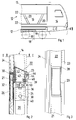
- FIG. 1 shows an end section of a rail vehicle 10 which has a car body 12 with side walls 14 which are designed as a framework 16, and wheel sets 18 with wheels 19 arranged on the car body 12 in a known manner.
- the truss 16 consists of an arrangement of inclined support profiles 20 and longitudinal profiles 22 running parallel to the car body 12, which are each connected to the support profiles 20, and in turn, as can be seen in particular in FIG. 2, on the inside and on the outside with provided with a cladding 24, 26 which lies closely against the framework 16 or is held by it.
- the manner in which the support profiles 20 are connected to the car body 12 or to the roof section 13 of the rail vehicle 10 is not shown in detail.
- FIG. 2 shows a vertical section through a support profile 20 in the region of the connection of a longitudinal profile 22, which clarifies the special design, which shows the cross-sectional shape, of the longitudinal profile 22.
- the longitudinal profile 22 is formed in two parts and consists of a load-bearing support part 21 and a holding part 23 securing its position with respect to the respective support profile 20.
- the support part 21 is recognizable at the points of assembly with the associated support profile 20 with one in FIG. 3
- Recess 28 provided on the inside of the car pointing longitudinal side of the longitudinal profile 22 attached from the outside to the respective support profiles 20 is formed.
- the support profile 20, like the support part 21 of the longitudinal profile, is designed as a hollow profile, but it has a rectangular cross section, preferably with rounded longitudinal edges, while the support part 21 of the longitudinal profile 22 is provided with a trapezoidal cross section, on the outside of which a cantilevered web 30 is molded.
- the web 30 serves both for alignment and for fastening the outer cladding 26 applied to the outside of the support part 21, which is formed from wall elements 32 and glass windows 34 prepared for installation.
- the wall elements 32 are preferably panels made of sandwich construction with a core formed from an insulating layer and a final lacquered top layer arranged at least on the outward-facing side, for example a thin covering made of light metal sheet or of wood or plastic. If necessary, both sides of the wall elements 32 can be provided with the ready-to-install cover layer.
- retaining tabs 36 are provided in the connection area of the associated longitudinal profile 22, which serve for support, that is to say support, and for fastening the supporting part of the longitudinal profile 22.
- the retaining tabs 36 are height-adjustable on the respective support profile 20, so that the alignment of the longitudinal profile 22 with respect to the car body 12 is possible without any problems.
- the attachment of the support part 21 of the longitudinal profile 22 to the respective holding tab 36 is carried out by means of holding screws 38, just as the connection of the holding part 23 to the support part 21 is provided by means of screws 39.
- the retaining tabs 36 are each provided with elongated holes 40 for the retaining screws 38.
- the holding part 23 which is connected to the supporting part 21 by means of the screws 39 mentioned, has an approximately U-shaped one Cross-section, one leg 42 of the U-shaped angle, namely the leg 42 to be connected to the supporting part 21 and arranged to the outside, has approximately twice the length of the other leg 44.
- the U-shaped profile of the holding part 23 forms an undercut or groove 46 for holding the inner lining 24, as will be described below.
- the cross section of the longer leg 42 has a recess 48, the depth of which corresponds at least to the thickness of the screw head of the screw 39 for fastening the holding part 23 to the support part 21.
- This ensures a flat contact of the inner lining 24, which is inserted with its upper longitudinal edge into the gap of the U-shaped holding part 23 and is thus held in a form-fitting manner.
- lips 50 or contact strips 52 made of elastic material, for example made of rubber, against which the inner lining 24 rests are inserted into the fillet 46 and arranged on the longer leg 42 .
- An adhesive connection for example by means of Velcro tape, a positive-locking clamp connection or an adhesive connection, can be provided for the lower fastening of the inner lining 24, that is to say the lower area not shown in the illustration in FIG. 2.
- a screw connection of the inner lining would have been possible since then, the aim of the present invention is to ensure a stable fastening of the inner lining 24, but without the fastening means being recognizable.
- the countersunk arrangement of the retaining screws 39 is also provided for fastening the retaining part 23 to the support part 21, which is achieved with the inner lining 24 covering the screw heads.
- the longitudinal profile 22 composed of the supporting part 21 and the holding part 23 is shown in plan view in the region of a connection point of a supporting profile 20, which engages in the recess 28 provided for this purpose in the longitudinal profile 22, that is to say in the supporting part 21. Further features relating to the design of the side wall structure or the framework 16 are provided with the corresponding reference numerals.
Landscapes
- Engineering & Computer Science (AREA)
- Life Sciences & Earth Sciences (AREA)
- Wood Science & Technology (AREA)
- Mechanical Engineering (AREA)
- Body Structure For Vehicles (AREA)
- Amplifiers (AREA)
- Control Of Stepping Motors (AREA)
- Transition And Organic Metals Composition Catalysts For Addition Polymerization (AREA)
- Door And Window Frames Mounted To Openings (AREA)
- Window Of Vehicle (AREA)
- Fittings On The Vehicle Exterior For Carrying Loads, And Devices For Holding Or Mounting Articles (AREA)
- Platform Screen Doors And Railroad Systems (AREA)
- Machines For Laying And Maintaining Railways (AREA)
- Chain Conveyers (AREA)
Abstract
Description
- Die Erfindung betrifft ein Schienenfahrzeug mit einem Wagenkasten mit Seitenwänden, die ein von Vertikalkräften aufnehmenden Stützprofilen und hiermit zusammenarbeitenden, horizontal angeordneten Längsprofilen gebildetes Fachwerk aufweisen, das jeweils auf der Außenseite und auf der Innenseite mit einer Verkleidung versehen ist, in welcher Verkleidung Fenster angeordnet sind, die jeweils von Profilen eingefaßt sind.
- Schienenfahrzeuge, insbesondere für den Personentransport, besitzen üblicherweise einen Wagenkasten, der auf einen Rahmen aufgesetzt ist und Seitenwände aus Stahl- oder Leichmetallblech aufweist. Zur Versteifung der Seitenwände sind häufig Stützprofile vorgesehen, die mit dem Wandblech verbunden sind, wobei für eventuell vorgesehene Fenster entsprechende Ausschnitte in die Seitenwände eingelassen sind, in welche die Fenster samt Rahmen und eingesetzt sind.
- Aus Gründen der Gewichtsersparnis ist vorgeschlagen worden, den Wagenkasten bei gleicher Verwindungssteifigkeit leichter zu gestalten und hierzu an Stelle von massiven Seitenwänden aus Blech stattdessen ein Fachwerk vorzusehen, das als Traggerüst für eine Verkleidung dient. Dabei kann die Verkleidung aus Platten aus Dünnblech oder aus Holz oder im Hinblick auf geringe Pflegeerfordernisse aus Kunststoff bestehen, die jeweils mit dem Fachwerk verbunden sind, zum Beispiel mittels Schrauben.
- Da neben der erforderlichen Funktionalität dieser neuartigen Fertigungsweise, das heißt der zuverlässigen Befestigung der Platten an dem Fachwerk, auch deren Aussehen von Bedeutung ist, wird von den Abnehmern derartiger Fahrzeuge Wert darauf gelegt, daß möglichst alle Teile, die eine Halte- oder Stützfunktion haben, nach Möglichkeit vollständig verdeckt sind.
- Ausgehend von diesem Stand der Technik ist es Aufgabe der Erfindung, ein Schienenfahrzeug der eingangs genannten Art zu schaffen, das den vorstehend genannten Erfordernissen entspricht und gleichzeitig eine möglichst einfache Montag ermöglicht.
- Diese Aufgabe wird erfindungsgemäß durch die Merkmale des Anspruchs 1 gelöst. Dementsprechend ist ein derartig ausgebildetes Schienenfahrzeug dadurch gekennzeichnet, daß die Stützprofile schräg zur Horizontalen verlaufend angeordnet sind und jeweils mit zugeordneten Längsprofilen verbunden sind, die wenigstens eine Ausnehmumg aufweisen, in welche jeweils ein Stützprofil eingreift, und daß das Längsprofil zur Befestigung der Verkleidung dient.
- Vorteilhafterweise ist gemäß einer bevorzugten Ausführungsform der Erfindung vorgesehen, daß die Außenverkleidung an den Längsprofilen mittels Klebeverbindung befestigt ist. Damit besteht gleichzeitig die Möglichkeit, die Einzelelemente der Außenverkleidung bündig, das heißt Stoß an Stoß, anzubringen.
- Ferner ist hiermit die Möglichkeit gegeben, bereits vorgefertigte Einzelelemente, das heißt zum Beispiel bereits fertiglackiert, im Endzustand für die Außenverkleidung zum Einbau vorzusehen, da von den noch durchzuführenden Montagearbeiten hierauf keine nachteiligen Auswirkungen ausgehen.
- Entsprechendes gilt auch für die Innenverkleidung, die gemäß einer weiteren bevorzugten Ausführungsform der Erfindung kraft- und formschlüssig vom Längsprofil gehalten ist, so daß auch hier keine störenden Halteelemente den optischen Eindruck beeinträchtigen bzw. zu einer Beschädigung bei der Montage führen.
- In vorteilhafter Weiterbildung der Erfindung ist vorgesehen, daß die jeweilige Ausnehmung in den Längsprofilen zu einer Längsseite, vorzugsweise zur Innenseite, hin offen ist.
- Hierdurch wird entsprechend einer weiteren Ausgestaltung der Erfindung die Voraussetzung dafür geschaffen, daß die Längsprofile an der betreffenden Seite , zum Beispiel innen, das jeweilige Stützprofil in dieser Ausnehmung aufnehmen, das heißt ringsum umfassen.
- Gemäß einer weiteren Ausgestaltung der Erfindung erweist es sich als vorteilhaft, daß die Fenster seitlich von den Stützprofilen sowie oben und unten jeweils von den Längsprofilen eingefaßt sind, so daß in horizontaler Richtung praktisch eine durchgehende Fensterfront ermöglicht ist, die lediglich durch die relativ wenigen, vorzugsweise schmalen Stützprofile unterbrochen ist.
- Dabei kann es ferner zweckmäßig sein, die Fensterscheiben bündig mit der Außenverkleidung abschließen zu lassen, indem die Fensterscheiben auf den Stützprofilen von außen aufgelegt und daran mittels elastischer Haltemittel, zum Beispiel mittels Silikonkautschuk, befestigt sind.
- Gemäß einer bevorzugten Ausgestaltung der Erfindung sind die Längsprofile aus einem Tragteil und einem Halteteil zusammengesetzt. Dabei ist in vorteilhafter Weiterbildung der Erfindung vorgesehen, daß das Tragteil mit den seitlichen Ausnehmungen versehen ist, in welche das betreffende Stützprofil eingreift Ferner erweist es sich als günstig, daß das Halteteil an der der Öffnungsseite der Ausnehmung gegenüberliegenden Innenseite gegen das Tragteil angelegt ist und daß das Halteteil mit dem Tragteil mechanisch verbunden ist.
- Vorteilhafterweise ist das Halteteil mit dem Tragteil mittels Halteschrauben verschraubt, wobei die Halteschrauben durch die anschließend montierte Innenverkleidung verdeckt sind.
- Eine weitere Ausführungsform der Erfindung sieht vor, daß an den Stützprofilen Haltelaschen angeordnet sind, auf welchen die Längsprofile aufliegen und mit denen die Längsprofile lösbar verbunden sind. Dabei erweist es sich als besonders günstig für die Montage, daß die Haltelaschen jeweils einstellbar an dem Stützprofil befestigt sind. Damit ist gewährleistet, daß das Höhenniveau der Längsprofile auf einfache Weise mittels der Haltelaschen einstellbar ist.
- Gemäß einer anderen Weiterbildung der Erfindung ist das Halteteil des Längsprofils mit einer Hinterschneidung bzw. Hohlkehle versehen, in welche die Innenverkleidung mit einer Längskante federnd eingreift und hierdurch gehalten ist.
- Vorteilhafterweise ist das Halteteil mit wenigstens einer Lippe aus elastischem Material, z.B. Gummi, versehen, an welche sich die Innenverkleidung anlegt. Damit wird vermieden, daß zwei starre Werkstoffe unmittelbar miteinander in mechanischem Kontakt stehen und eventuell auftretende Schwingungen ungedämpft übertragen.
- Darüberhinaus kann es von Vorteil sein, wenn das Halteteil in seiner Hinterschneidung bzw. Hohlkehle einen elastischen Einsatz aufweist, der mit der Innenverkleidung zusammenarbeitet. Dabei kann der elastische Einsatz gemeinsam mit der Verkleidung in die Hinterschneidung bzw. Hohlkehle eingebracht werden oder bereits darin vorgesehen sein, bevor die Verkleidung hierin eingeführt wird.
- Diese und weitere vorteilhafte Ausgestaltungen und Verbesserungen der Erfindung sind Gegenstand der Unteransprüche.
- Anhand eines in der schematischen Zeichnung dargestellten Ausführungsbeispieles sollen die Erfindung, vorteilhafte Ausgestaltungen und Verbesserungen der Erfindung sowie besondere Vorteile der Erfindung näher erläutert und beschrieben werden.
- Es zeigen:
- Fig. 1
- eine teilweise Seitenansicht eines Schienenfahrzeuges mit den aus den erfindungsgemäßen Stütz- und Längsprofilen gebildeten Fachwerk;
- Fig. 2
- eine Schnittansicht durch ein Stützprofil mit eingesetztem Längsprofil entsprechend Figur 1;
- Fig. 3
- eine Schnittansicht der Anordnung gemäß Fig. 2 entlang der Schnittlinie II-II in Fig. 2 und
- In Fig. 1 ist ein stirnseitiger Abschnitt eines Schienenfahrzeugs 10 dargestellt, das einen Wagenkasten 12 mit Seitenwänden 14 aufweist, die als Fachwerk 16 ausgebildet sind, sowie an dem Wagenkasten 12 in bekannter Weise angeordnete Radsätze 18 mit Rädern 19.
- Das Fachwerk 16 besteht aus einer Anordnung von schrägangestellten Stützprofilen 20 und parallel zum Wagenkasten 12 verlaufenden Längsprofilen 22, die mit den Stützprofilen 20 jeweils verbunden sind, und ist seinerseits, wie insbesondere aus Fig. 2 hervorgeht, auf der Innenseite und auf der Außenseite jeweils mit einer Verkleidung 24, 26 versehen, die eng am Fachwerk 16 anliegt bzw. von diesem gehalten ist. Nicht näher dargestellt ist die Art und Weise, wie die Stützprofile 20 mit dem Wagenkasten 12 beziehungsweise mit der Dachpartie 13 des Schienenenfahrzeuges 10 verbunden sind.
- In Fig. 2 ist ein vertikaler Schnitt durch ein Stützprofil 20 im Bereich des Anschlusses eines Längsprofiles 22 gezeigt, der die besondere Gestaltung, das die Querschnittsform, des Längsprofils 22 verdeutlicht. Das Längsprofil 22 ist zweiteilig ausgebildet und besteht aus einem lastaufnehmenden Tragteil 21 und einem dessen Lage in bezug auf das jeweilige Stützprofil 20 sichernden Halteteil 23. Das Tragteil 21 ist jeweils an den Stellen des Zusammenbaus mit dem zugeordneten Stützprofil 20 mit einer in Fig. 3 erkennbaren Ausnehmung 28 versehen, die auf der in das Wageninnere weisenden Längsseite des von außen an die jeweiligen Stützprofile 20 angesetzten Längsprofils 22 eingeformt ist.
- Das Stützprofil 20 ist ebenso wie das Tragteil 21 des Längsprofils als Hohlprofil ausgebildet, Es besitzt jedoch einen rechteckigen Querschnitt, vorzugsweise mit abgerundeten Längskanten, während das Tragteil 21 des Längsprofils 22 mit einem trapezförmige Querschnitt versehen ist, an dessen nach außen weisender Außenseite ein auskragender Steg 30 angeformt ist. Der Steg 30 dient sowohl zur Ausrichtung als auch zur Befestigung der an die Außenseite des Tragteils 21 angelegten Außenverkleidung 26, die aus einbaufertig vorbereiteten Wandelementen 32 und Glasfenstern 34 gebildet ist.
- Die Wandelemente 32 sind vorzugsweise in Sandwich-Bauweise gefertigte Platten mit einem aus einer Isolierschicht gebildeten Kern und einer zumindest auf der nach außen weisenden Seite angeordneten endlackierten Deckschicht, z.B ein dünner Belag aus Leichtmetallblech oder aus Holz beziehungsweise aus Kunststoff. Gegebenenfalls können beide Seiten der Wandelemente 32 mit der einbaufertigen Deckschicht versehen sein.
- An den schräg zur Horizontalen angestellten Stützprofilen 20 sind jeweils im Anschlußbereich des zugeordneten Längsprofils 22 Haltelaschen 36 vorgesehen, welche zur Auflage, das heißt Abstützung, und zur Befestigung des Tragteils des Längsprofils 22 dienen. Die Haltelaschen 36 sind höhenverstellbar am jeweiligen Stützprofil 20 angebracht, so daß das Ausrichten des Längsprofils 22 in Bezug auf den Wagenkasten 12 problemlos möglich ist. Die Befestigung des Tragteils 21 des Längsprofils 22 an der jeweiligen Haltelasche 36 erfolgt mittels Halteschrauben 38, ebenso wie die Verbindung des Halteteils 23 mit dem Tragteil 21 mittels Schrauben 39 vorgesehen ist. Dabei sind die Haltelaschen 36 jeweils mit Langlöchern 40 für die Halteschrauben 38 versehen.
- Das Halteteil 23, das mittels der erwähnten Schrauben 39 mit dem Tragteil 21 verbunden ist, besitzt einen annähernd U-förmigen Querschnitt, wobei ein Schenkel 42 des U-förmigen Winkels, nämlich der mit dem Tragteil 21 zu verbindende, zur Außenseite hin angeordnete Schenkel 42 etwa die doppelte Länge gegenüber dem anderen Schenkel 44 aufweist. Dabei bildet die U-förmige Profilierung des Halteteils 23 eine Hinterschneidung bzw. Hohlkehle 46 zur Halterung der Innenverkleidung 24, wie nachfolgend beschrieben wird.
- Gemäß dem in Fig. 2 gezeigten Beispiel besitzt der Querschnitt des längeren Schenkels 42 eine Einziehung 48, deren Tiefe wenigstens der Dicke des Schraubenkopfes der Schraube 39 zur Befestigung des Halteteils 23 am Tragteil 21 entspricht. Hierdurch ist eine ebene Anlage der Innverkleidung 24 gewährleistet, die mit ihrer oberen Längskante in den Spalt des U-förmigen Halteteils 23 eingeführt und so formschlüssig gehalten ist. Um mögliches Spiel innerhalb der Hohlkehle 46 und hierdurch verursachte Geräuschbildung der Innenverkleidung 24 zu verhindern, dienen in die Hohlkehle 46 eingesetzte sowie an dem längeren Schenkel 42 angeordnete Lippen 50 oder Anlagestreifen 52 aus elastischem Material, zum Beispiel aus Gummi, an welchen die Innenverkleidung 24 anliegt.
- Zur unteren Befestigung der Innenverkleidung 24, das heißt des in der Darstellung von Fig. 2 nicht näher gezeigten unteren Bereichs, kann eine Haftverbindung, zum Beispiel mittels Klettband, eine formschlüssige Klemmverbindung oder eine Klebeverbindung vorgesehen sein. Zwar wäre auch eine Schraubverbindung der Innenverkleidung wie seither möglich, doch ist mit der vorliegenden Erfindung bezweckt, eine zwar stabile Befestigung der Innenverkleidung 24 zu gewährleisten, doch ohne daß die Befestigungsmittel erkennbar sind.
- Zu diesem Zweck ist auch die versenkte Anordnung der Halteschrauben 39 für die Befestigung des Halteteils 23 am Tragteil 21 vorgesehen, die mit der die Schraubenköpfe überdeckenden Innenverkleidung 24 erreicht wird.
- In Fig. 3 ist das aus Tragteil 21 und Halteteil 23 zusammengesetzte Längsprofil 22 im Bereich einer Anschlußstelle eines Stützprofils 20 in Draufsicht gezeigt, welches in die hierfür im Längsprofil 22, das heißt im Tragteil 21, vorgesehene Ausnehmung 28 eingreift. Weitere die Ausgestaltung des Seitenwandaufbaus beziehungsweise des Fachwerks 16 betreffende Merkmale sind mit den entsprechenden Bezugsziffern versehen.
Claims (16)
- Schienenfahrzeug (10) mit einem Wagenkasten (12) mit Seitenwänden (14), die ein von Vertikalkräften aufnehmenden Stützprofilen (20) und hiermit zusammenarbeitenden, horizontal angeordneten Längsprofilen (22) gebildetes Fachwerk (16) aufweisen, das jeweils auf der Außenseite und auf der Innenseite mit einer Verkleidung (24, 26) versehen ist, in welcher Verkleidung (24, 26) Fenster (34) angeordnet sind, die jeweils von Profilen (20, 22) eingefaßt sind, dadurch gekennzeichnet, daß die Stützprofile (20) schräg zur Horizontalen verlaufend angeordnet sind und jeweils mit zugeordneten Längsprofilen (22) verbunden sind, die wenigstens eine Ausnehmumg (28) aufweisen, in welche jeweils eines der Stützprofile (20) eingreift, und daß das Längsprofil (22) zur Befestigung der Verkleidung (24, 26) dient.
- Schienenfahrzeug nach Anspruch 1, dadurch gekennzeichnet, daß die jeweilige Ausnehmung (28) in den Längsprofilen (22) zu einer Längsseite hin offen ist.
- Schienenfahrzeug nach Anspruch 1 oder 2, dadurch gekennzeichnet, daß die Längsprofile (22) mit der zugeordneten Ausnehmung (28) an dem jeweiligen Stützprofil (20) angesetzt sind.
- Schienenfahrzeug nach einem der Ansprüche 1 bis 3, dadurch gekennzeichnet, daß die Fenster (34) seitlich von den Stützprofilen (20) sowie oben und unten jeweils von den Längsprofilen (22) eingefaßt sind.
- Schienenfahrzeug nach einem der vorherigen Ansprüche, dadurch gekennzeichnet, daß die Längsprofile (22) aus einem Tragteil (21) und einem Halteteil (23) zusammengesetzt sind.
- Schienenfahrzeug nach einem der vorherigen Ansprüche, dadurch gekennzeichnet, daß das Tragteil (21) die wenigstens eine Ausnehmung (28) aufweist, in welche Ausnehmung (28) das zugeordnete Stützprofil (20) seitlich eingreift, daß das Halteteil (23) von der der Öffnungsseite der Ausnehmung (28) gegenüberliegenden Seite gegen das Tragteil (21) angelegt ist und daß das Halteteil (23) mit dem Tragteil (21) lösbar verbunden ist.
- Schienenfahrzeug nach einem der vorherigen Ansprüche, dadurch gekennzeichnet, an den Stützprofilen (20) Haltelaschen (36) angeordnet sind, auf welchen die Längsprofile (22) aufliegen und mit denen die Längsprofile (22) lösbar verbunden sind.
- Schienenfahrzeug nach Anspruch 7, dadurch gekennzeichnet, daß die Haltelaschen (36) jeweils einstellbar an den Stützprofilen (20) befestigt sind.
- Schienenfahrzeug nach einem der vorherigen Ansprüche 7 oder 8, dadurch gekennzeichnet, daß das Höhenniveau der Längsprofile (22) mittels der Haltelaschen (36) einstellbar ist.
- Schienenfahrzeug nach einem der vorherigen Ansprüche, dadurch gekennzeichnet, die Außenverkleidung (26) an den Längsprofilen (22) mittels Klebeverbindung befestigt ist.
- Schienenfahrzeug nach einem der vorherigen Ansprüche, dadurch gekennzeichnet, daß die Innenverkleidung (24) kraft- und formschlüssig vom Längsprofil (22) gehalten ist.
- Schienenfahrzeug nach Anspruch 11, dadurch gekennzeichnet, daß das Halteteil (23) des Längsprofils (22) mit einer Hinterschneidung bzw. Hohlkehle (46) versehen ist, in welche die Innenverkleidung (24) mit einer Längskante federnd eingreift und hierdurch gehalten ist.
- Schienenfahrzeug nach Anspruch 12, dadurch gekennzeichnet, daß das Halteteil mit wenigstens einer Lippe (50) aus elastischem Material, z.B. Gummi, versehen ist, an welche sich die Innenverkleidung (24) anlegt.
- Schienenfahrzeug nach Anspruch 12 oder 13, dadurch gekennzeichnet, daß das Halteteil (23) in seiner Hinterschneidung bzw. Hohlkehle (46) einen elastischen Einsatz (52) aufweist, der mit der Innenverkleidung (24) zusammenarbeitet.
- Schienenfahrzeug nach einem der vorherigen Ansprüche, dadurch gekennzeichnet, daß das Halteteil (23) mit dem Tragteil (21) mittels Halteschrauben (39) verbunden ist.
- Schienenfahrzeug nach Anspruch 16, dadurch gekennzeichnet, daß die Halteschrauben (39) durch die Innenverkleidung (24) verdeckt sind.
Applications Claiming Priority (2)
| Application Number | Priority Date | Filing Date | Title |
|---|---|---|---|
| DE19512631A DE19512631A1 (de) | 1995-04-05 | 1995-04-05 | Schienenfahrzeug |
| DE19512631 | 1995-04-05 |
Publications (2)
| Publication Number | Publication Date |
|---|---|
| EP0736436A1 true EP0736436A1 (de) | 1996-10-09 |
| EP0736436B1 EP0736436B1 (de) | 1998-12-02 |
Family
ID=7758781
Family Applications (1)
| Application Number | Title | Priority Date | Filing Date |
|---|---|---|---|
| EP96105194A Expired - Lifetime EP0736436B1 (de) | 1995-04-05 | 1996-04-01 | Schienenfahrzeug |
Country Status (6)
| Country | Link |
|---|---|
| US (1) | US5685230A (de) |
| EP (1) | EP0736436B1 (de) |
| AT (1) | ATE173988T1 (de) |
| DE (2) | DE19512631A1 (de) |
| DK (1) | DK0736436T3 (de) |
| ES (1) | ES2127584T3 (de) |
Cited By (1)
| Publication number | Priority date | Publication date | Assignee | Title |
|---|---|---|---|---|
| WO2018059865A1 (de) * | 2016-09-29 | 2018-04-05 | Siemens Aktiengesellschaft | Schienenfahrzeug |
Families Citing this family (1)
| Publication number | Priority date | Publication date | Assignee | Title |
|---|---|---|---|---|
| US12397697B2 (en) * | 2022-01-29 | 2025-08-26 | Palfinger Usa, Llc | Liftgate mounting system and method |
Citations (2)
| Publication number | Priority date | Publication date | Assignee | Title |
|---|---|---|---|---|
| FR1578442A (de) * | 1968-08-19 | 1969-08-14 | ||
| DE9415771U1 (de) * | 1994-09-30 | 1994-12-15 | ABB Henschel AG, 13509 Berlin | Schienengebundener Dieseltriebwagen |
Family Cites Families (12)
| Publication number | Priority date | Publication date | Assignee | Title |
|---|---|---|---|---|
| US854404A (en) * | 1906-08-25 | 1907-05-21 | Standard Steel Car Co | Frame for passenger and like cars. |
| US849826A (en) * | 1906-12-14 | 1907-04-09 | Hugh Hazelton | Passenger-car construction. |
| US1244947A (en) * | 1915-03-02 | 1917-10-30 | Lewis B Stillwell | Railway-car. |
| US2145064A (en) * | 1935-12-06 | 1939-01-24 | American Car & Foundry Co | Light weight car construction |
| US2216025A (en) * | 1937-11-26 | 1940-09-24 | Budd Edward G Mfg Co | Vehicle side frame truss |
| CH601045A5 (de) * | 1976-09-16 | 1978-06-30 | Schweizerische Lokomotiv | |
| JPS5881855A (ja) * | 1981-11-11 | 1983-05-17 | 株式会社日立製作所 | 車両構体の構造 |
| US4573733A (en) * | 1982-11-19 | 1986-03-04 | General Motors Corporation | Apparatus for mounting plastic body panel |
| AU3605484A (en) * | 1983-12-23 | 1985-06-27 | Swiss Aluminium Ltd. | Vehicle superstructure, in particular for railway carriages for passenger transport |
| US4607877A (en) * | 1985-09-30 | 1986-08-26 | General Motors Corporation | Vehicle body panel arrangement |
| JP2904828B2 (ja) * | 1989-11-27 | 1999-06-14 | 富士重工業株式会社 | 車両の車体構造 |
| DE9306853U1 (de) * | 1993-05-06 | 1993-07-08 | Schenk, Hans, 2300 Kiel | Wagenkasten mit Fachwerkseitenwand für einteilige und für Gelenkfahrzeuge |
-
1995
- 1995-04-05 DE DE19512631A patent/DE19512631A1/de not_active Ceased
-
1996
- 1996-04-01 ES ES96105194T patent/ES2127584T3/es not_active Expired - Lifetime
- 1996-04-01 DE DE59600886T patent/DE59600886D1/de not_active Expired - Lifetime
- 1996-04-01 EP EP96105194A patent/EP0736436B1/de not_active Expired - Lifetime
- 1996-04-01 DK DK96105194T patent/DK0736436T3/da active
- 1996-04-01 AT AT96105194T patent/ATE173988T1/de active
- 1996-04-04 US US08/627,569 patent/US5685230A/en not_active Expired - Fee Related
Patent Citations (2)
| Publication number | Priority date | Publication date | Assignee | Title |
|---|---|---|---|---|
| FR1578442A (de) * | 1968-08-19 | 1969-08-14 | ||
| DE9415771U1 (de) * | 1994-09-30 | 1994-12-15 | ABB Henschel AG, 13509 Berlin | Schienengebundener Dieseltriebwagen |
Cited By (2)
| Publication number | Priority date | Publication date | Assignee | Title |
|---|---|---|---|---|
| WO2018059865A1 (de) * | 2016-09-29 | 2018-04-05 | Siemens Aktiengesellschaft | Schienenfahrzeug |
| EP3519270B1 (de) | 2016-09-29 | 2021-06-30 | Siemens Mobility GmbH | Schienenfahrzeug |
Also Published As
| Publication number | Publication date |
|---|---|
| ES2127584T3 (es) | 1999-04-16 |
| ATE173988T1 (de) | 1998-12-15 |
| DK0736436T3 (da) | 1999-06-23 |
| DE19512631A1 (de) | 1996-10-10 |
| US5685230A (en) | 1997-11-11 |
| EP0736436B1 (de) | 1998-12-02 |
| DE59600886D1 (de) | 1999-01-14 |
Similar Documents
| Publication | Publication Date | Title |
|---|---|---|
| DE69125572T2 (de) | Tragschiene für eine gläserne Tür oder Trennwand | |
| DE60111600T2 (de) | Wagenkasten eines Schienenfahrzeugs | |
| EP1198376B1 (de) | Fussboden für fahrzeuge, insbesondere schienenfahrzeuge zur personenbeförderung | |
| EP1344712A2 (de) | Verbundbauteil, insbesondere Fahrzeuganbauteil oder Fahrzeugpaneel | |
| DE69600926T2 (de) | Gitterträger für tragende geländer von hängebühne | |
| DE10110996B4 (de) | Wandelement für eine Ladegutsicherungsvorrichtung und Verfahren zu dessen Herstellung | |
| DE102008021224B4 (de) | Schienenfahrzeug | |
| DE69929707T2 (de) | Ein mit befestigungsvorrichtung(en) zusammengesetzter aufzug | |
| DE19744832C2 (de) | Anordnung für den Einbau eines Fensterrahmens | |
| WO2008092699A1 (de) | Revisionsvorrichtung, insbesondere revisionsabdeckung | |
| DE1908567A1 (de) | Kombinierte Form- und Verglasungsleiste als Profilstab insbesondere zum Halten einer Glasscheibe vorzugsweise an einem Rahmen | |
| EP0692208B1 (de) | Schublade | |
| AT516721B1 (de) | Geländer und Verfahren zur Herstellung eines Geländers | |
| DE9313426U1 (de) | Lüftungsvorrichtung für Räume | |
| EP0736436B1 (de) | Schienenfahrzeug | |
| DE202016105087U1 (de) | Halteschiene für einen französischen Balkon sowie Haltevorrichtung und Anordnung dafür | |
| EP0755838B1 (de) | Gerippestruktur mit Türrahmen und Wandelementen | |
| DE3404785A1 (de) | Fahrbare arbeitsmaschine mit einem aufbau | |
| EP0253312A2 (de) | Kabinenkonstruktion | |
| DE4300717A1 (de) | Inneneinrichtung für ein Schienenfahrzeug zur Personenbeförderung | |
| DE9201336U1 (de) | Fenster- oder Türrahmen, insbesondere mit Rolladen- oder Jalousettenkasten | |
| DE69105380T2 (de) | Treppengeländer. | |
| DE29819674U1 (de) | Innenverkleidung | |
| EP0835979B1 (de) | Rolladenvorrichtung und Innenblende hierfür | |
| DE19933252B4 (de) | Trennwandsystem |
Legal Events
| Date | Code | Title | Description |
|---|---|---|---|
| PUAI | Public reference made under article 153(3) epc to a published international application that has entered the european phase |
Free format text: ORIGINAL CODE: 0009012 |
|
| AK | Designated contracting states |
Kind code of ref document: A1 Designated state(s): AT BE CH DE DK ES FI FR IT LI |
|
| 17P | Request for examination filed |
Effective date: 19961106 |
|
| GRAG | Despatch of communication of intention to grant |
Free format text: ORIGINAL CODE: EPIDOS AGRA |
|
| RAP1 | Party data changed (applicant data changed or rights of an application transferred) |
Owner name: ABB DAIMLER-BENZ TRANSPORTATION (TECHNOLOGY) GMBH |
|
| GRAG | Despatch of communication of intention to grant |
Free format text: ORIGINAL CODE: EPIDOS AGRA |
|
| GRAH | Despatch of communication of intention to grant a patent |
Free format text: ORIGINAL CODE: EPIDOS IGRA |
|
| 17Q | First examination report despatched |
Effective date: 19980518 |
|
| GRAH | Despatch of communication of intention to grant a patent |
Free format text: ORIGINAL CODE: EPIDOS IGRA |
|
| GRAA | (expected) grant |
Free format text: ORIGINAL CODE: 0009210 |
|
| AK | Designated contracting states |
Kind code of ref document: B1 Designated state(s): AT BE CH DE DK ES FI FR IT LI |
|
| REF | Corresponds to: |
Ref document number: 173988 Country of ref document: AT Date of ref document: 19981215 Kind code of ref document: T |
|
| REG | Reference to a national code |
Ref country code: CH Ref legal event code: EP |
|
| REF | Corresponds to: |
Ref document number: 59600886 Country of ref document: DE Date of ref document: 19990114 |
|
| ITF | It: translation for a ep patent filed | ||
| ET | Fr: translation filed | ||
| REG | Reference to a national code |
Ref country code: ES Ref legal event code: FG2A Ref document number: 2127584 Country of ref document: ES Kind code of ref document: T3 |
|
| REG | Reference to a national code |
Ref country code: DK Ref legal event code: T3 |
|
| PLBE | No opposition filed within time limit |
Free format text: ORIGINAL CODE: 0009261 |
|
| STAA | Information on the status of an ep patent application or granted ep patent |
Free format text: STATUS: NO OPPOSITION FILED WITHIN TIME LIMIT |
|
| 26N | No opposition filed | ||
| REG | Reference to a national code |
Ref country code: CH Ref legal event code: PFA Free format text: ABB DAIMLER-BENZ TRANSPORTATION (TECHNOLOGY) GMBH TRANSFER- DAIMLERCHRYSLER AG |
|
| REG | Reference to a national code |
Ref country code: CH Ref legal event code: NV Representative=s name: DIPL.-ING. ETH H. R. WERFFELI PATENTANWALT |
|
| REG | Reference to a national code |
Ref country code: FR Ref legal event code: TP Ref country code: FR Ref legal event code: CD |
|
| PGFP | Annual fee paid to national office [announced via postgrant information from national office to epo] |
Ref country code: DK Payment date: 20120418 Year of fee payment: 17 Ref country code: BE Payment date: 20120418 Year of fee payment: 17 |
|
| PGFP | Annual fee paid to national office [announced via postgrant information from national office to epo] |
Ref country code: FI Payment date: 20120411 Year of fee payment: 17 Ref country code: FR Payment date: 20120507 Year of fee payment: 17 |
|
| PGFP | Annual fee paid to national office [announced via postgrant information from national office to epo] |
Ref country code: IT Payment date: 20120424 Year of fee payment: 17 |
|
| PGFP | Annual fee paid to national office [announced via postgrant information from national office to epo] |
Ref country code: ES Payment date: 20120425 Year of fee payment: 17 |
|
| BERE | Be: lapsed |
Owner name: *ABB DAIMLER-BENZ TRANSPORTATION (TECHNOLOGY) G.M. Effective date: 20130430 |
|
| REG | Reference to a national code |
Ref country code: DK Ref legal event code: EBP Effective date: 20130430 |
|
| PG25 | Lapsed in a contracting state [announced via postgrant information from national office to epo] |
Ref country code: BE Free format text: LAPSE BECAUSE OF NON-PAYMENT OF DUE FEES Effective date: 20130430 |
|
| REG | Reference to a national code |
Ref country code: FR Ref legal event code: ST Effective date: 20131231 |
|
| PG25 | Lapsed in a contracting state [announced via postgrant information from national office to epo] |
Ref country code: FR Free format text: LAPSE BECAUSE OF NON-PAYMENT OF DUE FEES Effective date: 20130430 Ref country code: IT Free format text: LAPSE BECAUSE OF NON-PAYMENT OF DUE FEES Effective date: 20130401 Ref country code: FI Free format text: LAPSE BECAUSE OF NON-PAYMENT OF DUE FEES Effective date: 20130401 |
|
| PG25 | Lapsed in a contracting state [announced via postgrant information from national office to epo] |
Ref country code: DK Free format text: LAPSE BECAUSE OF NON-PAYMENT OF DUE FEES Effective date: 20130430 |
|
| REG | Reference to a national code |
Ref country code: ES Ref legal event code: FD2A Effective date: 20140610 |
|
| PG25 | Lapsed in a contracting state [announced via postgrant information from national office to epo] |
Ref country code: ES Free format text: LAPSE BECAUSE OF NON-PAYMENT OF DUE FEES Effective date: 20130402 |
|
| PGFP | Annual fee paid to national office [announced via postgrant information from national office to epo] |
Ref country code: CH Payment date: 20140418 Year of fee payment: 19 Ref country code: AT Payment date: 20140411 Year of fee payment: 19 |
|
| REG | Reference to a national code |
Ref country code: DE Ref legal event code: R082 Ref document number: 59600886 Country of ref document: DE Representative=s name: MAI, OPPERMANN & PARTNER I. L., DE |
|
| PGFP | Annual fee paid to national office [announced via postgrant information from national office to epo] |
Ref country code: DE Payment date: 20150421 Year of fee payment: 20 |
|
| REG | Reference to a national code |
Ref country code: CH Ref legal event code: PL |
|
| REG | Reference to a national code |
Ref country code: AT Ref legal event code: MM01 Ref document number: 173988 Country of ref document: AT Kind code of ref document: T Effective date: 20150401 |
|
| PG25 | Lapsed in a contracting state [announced via postgrant information from national office to epo] |
Ref country code: CH Free format text: LAPSE BECAUSE OF NON-PAYMENT OF DUE FEES Effective date: 20150430 Ref country code: LI Free format text: LAPSE BECAUSE OF NON-PAYMENT OF DUE FEES Effective date: 20150430 |
|
| PG25 | Lapsed in a contracting state [announced via postgrant information from national office to epo] |
Ref country code: AT Free format text: LAPSE BECAUSE OF NON-PAYMENT OF DUE FEES Effective date: 20150401 |
|
| REG | Reference to a national code |
Ref country code: DE Ref legal event code: R071 Ref document number: 59600886 Country of ref document: DE |