EP0736436A1 - Véhicule ferroviaire - Google Patents
Véhicule ferroviaire Download PDFInfo
- Publication number
- EP0736436A1 EP0736436A1 EP96105194A EP96105194A EP0736436A1 EP 0736436 A1 EP0736436 A1 EP 0736436A1 EP 96105194 A EP96105194 A EP 96105194A EP 96105194 A EP96105194 A EP 96105194A EP 0736436 A1 EP0736436 A1 EP 0736436A1
- Authority
- EP
- European Patent Office
- Prior art keywords
- rail vehicle
- profiles
- vehicle according
- longitudinal
- support
- Prior art date
- Legal status (The legal status is an assumption and is not a legal conclusion. Google has not performed a legal analysis and makes no representation as to the accuracy of the status listed.)
- Granted
Links
- 238000005253 cladding Methods 0.000 claims abstract description 16
- 239000000853 adhesive Substances 0.000 claims abstract description 5
- 230000001070 adhesive effect Effects 0.000 claims abstract description 5
- 239000013013 elastic material Substances 0.000 claims description 3
- 229920001971 elastomer Polymers 0.000 claims description 3
- 239000002184 metal Substances 0.000 description 4
- 238000009434 installation Methods 0.000 description 2
- 239000004033 plastic Substances 0.000 description 2
- 239000002023 wood Substances 0.000 description 2
- 206010067482 No adverse event Diseases 0.000 description 1
- 229910000831 Steel Inorganic materials 0.000 description 1
- 238000010276 construction Methods 0.000 description 1
- 230000001419 dependent effect Effects 0.000 description 1
- 230000002349 favourable effect Effects 0.000 description 1
- 239000011521 glass Substances 0.000 description 1
- 238000012423 maintenance Methods 0.000 description 1
- 238000004519 manufacturing process Methods 0.000 description 1
- 239000000463 material Substances 0.000 description 1
- 229920002379 silicone rubber Polymers 0.000 description 1
- 239000004945 silicone rubber Substances 0.000 description 1
- 239000007787 solid Substances 0.000 description 1
- 239000010959 steel Substances 0.000 description 1
- 230000000007 visual effect Effects 0.000 description 1
Images
Classifications
-
- B—PERFORMING OPERATIONS; TRANSPORTING
- B61—RAILWAYS
- B61D—BODY DETAILS OR KINDS OF RAILWAY VEHICLES
- B61D17/00—Construction details of vehicle bodies
- B61D17/04—Construction details of vehicle bodies with bodies of metal; with composite, e.g. metal and wood body structures
- B61D17/08—Sides
-
- B—PERFORMING OPERATIONS; TRANSPORTING
- B61—RAILWAYS
- B61D—BODY DETAILS OR KINDS OF RAILWAY VEHICLES
- B61D17/00—Construction details of vehicle bodies
- B61D17/04—Construction details of vehicle bodies with bodies of metal; with composite, e.g. metal and wood body structures
- B61D17/043—Construction details of vehicle bodies with bodies of metal; with composite, e.g. metal and wood body structures connections between superstructure sub-units
Definitions
- the invention relates to a rail vehicle with a car body with side walls, which have a supporting profile that absorbs vertical forces and cooperate with this, horizontally arranged longitudinal profiles, which is provided on the outside and on the inside with a panel, in which panel windows are arranged, which are bordered by profiles.
- Rail vehicles in particular for the transport of people, usually have a car body which is placed on a frame and has side walls made of sheet steel or light metal.
- support profiles are often provided, which are connected to the wall plate, with corresponding cutouts being made in the side walls into which windows, including frames and are inserted, for windows that may be provided.
- the car body lighter with the same torsional stiffness and instead to provide a framework instead of solid side walls made of sheet metal, which serves as a supporting structure for a cladding.
- the cladding can consist of sheets of thin sheet metal or wood or, in view of low maintenance requirements, of plastic, which are each connected to the framework, for example by means of screws.
- a rail vehicle designed in this way is characterized in that the support profiles are arranged obliquely to the horizontal and are each connected to associated longitudinal profiles which have at least one recess, in each of which a support profile engages, and that the longitudinal profile serves to fasten the cladding.
- the outer cladding is fastened to the longitudinal profiles by means of an adhesive connection. This also enables the individual elements of the outer cladding to be fitted flush, i.e., butt to butt.
- this provides the possibility of providing ready-made individual elements, that is to say, for example already already finished, in the final state for the outer cladding for installation, since the assembly work still to be carried out has no adverse effects on this.
- the inner lining which according to a further preferred embodiment of the invention is held non-positively and positively by the longitudinal profile, so that no disturbing holding elements impair the visual impression or lead to damage during assembly.
- the respective recess in the longitudinal profiles is open to one long side, preferably to the inside.
- the prerequisite is created for the longitudinal profiles on the relevant side, for example inside, to receive the respective support profile in this recess, that is to say encompass it all around.
- the windows are bordered laterally by the support profiles and above and below by the longitudinal profiles, so that practically a continuous window front is made possible in the horizontal direction, only by the relatively few, preferably narrow support profiles is interrupted.
- window panes flush with the outer cladding, in that the window panes are placed on the support profiles from the outside and are attached to them by means of elastic holding means, for example using silicone rubber.
- the longitudinal profiles are composed of a supporting part and a holding part. It is provided in an advantageous development of the invention that the support member is provided with the lateral recesses in which the relevant support profile engages. Furthermore, it proves to be advantageous that the holding member is placed against the support member on the inside opposite the opening side of the recess and that the holding part is mechanically connected to the supporting part.
- the holding part is advantageously screwed to the supporting part by means of holding screws, the holding screws being covered by the subsequently mounted inner lining.
- a further embodiment of the invention provides that retaining lugs are arranged on the support profiles, on which the longitudinal profiles rest and with which the longitudinal profiles are detachably connected. It proves to be particularly favorable for the assembly that the retaining tabs are each fastened to the support profile in an adjustable manner. This ensures that the height level of the longitudinal profiles can be adjusted in a simple manner by means of the retaining tabs.
- the holding part of the longitudinal profile is provided with an undercut or fillet in which the inner lining engages with a longitudinal edge and is held thereby.
- the holding part is advantageously provided with at least one lip made of elastic material, e.g. Rubber, provided, to which the inner lining lies. This avoids that two rigid materials are in direct mechanical contact with one another and that any vibrations that occur are transmitted undamped.
- elastic material e.g. Rubber
- the holding part in its undercut or fillet has an elastic insert that cooperates with the inner lining.
- the elastic insert can be introduced into the undercut or fillet together with the cladding or can already be provided therein before the cladding is inserted therein.
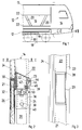
- FIG. 1 shows an end section of a rail vehicle 10 which has a car body 12 with side walls 14 which are designed as a framework 16, and wheel sets 18 with wheels 19 arranged on the car body 12 in a known manner.
- the truss 16 consists of an arrangement of inclined support profiles 20 and longitudinal profiles 22 running parallel to the car body 12, which are each connected to the support profiles 20, and in turn, as can be seen in particular in FIG. 2, on the inside and on the outside with provided with a cladding 24, 26 which lies closely against the framework 16 or is held by it.
- the manner in which the support profiles 20 are connected to the car body 12 or to the roof section 13 of the rail vehicle 10 is not shown in detail.
- FIG. 2 shows a vertical section through a support profile 20 in the region of the connection of a longitudinal profile 22, which clarifies the special design, which shows the cross-sectional shape, of the longitudinal profile 22.
- the longitudinal profile 22 is formed in two parts and consists of a load-bearing support part 21 and a holding part 23 securing its position with respect to the respective support profile 20.
- the support part 21 is recognizable at the points of assembly with the associated support profile 20 with one in FIG. 3
- Recess 28 provided on the inside of the car pointing longitudinal side of the longitudinal profile 22 attached from the outside to the respective support profiles 20 is formed.
- the support profile 20, like the support part 21 of the longitudinal profile, is designed as a hollow profile, but it has a rectangular cross section, preferably with rounded longitudinal edges, while the support part 21 of the longitudinal profile 22 is provided with a trapezoidal cross section, on the outside of which a cantilevered web 30 is molded.
- the web 30 serves both for alignment and for fastening the outer cladding 26 applied to the outside of the support part 21, which is formed from wall elements 32 and glass windows 34 prepared for installation.
- the wall elements 32 are preferably panels made of sandwich construction with a core formed from an insulating layer and a final lacquered top layer arranged at least on the outward-facing side, for example a thin covering made of light metal sheet or of wood or plastic. If necessary, both sides of the wall elements 32 can be provided with the ready-to-install cover layer.
- retaining tabs 36 are provided in the connection area of the associated longitudinal profile 22, which serve for support, that is to say support, and for fastening the supporting part of the longitudinal profile 22.
- the retaining tabs 36 are height-adjustable on the respective support profile 20, so that the alignment of the longitudinal profile 22 with respect to the car body 12 is possible without any problems.
- the attachment of the support part 21 of the longitudinal profile 22 to the respective holding tab 36 is carried out by means of holding screws 38, just as the connection of the holding part 23 to the support part 21 is provided by means of screws 39.
- the retaining tabs 36 are each provided with elongated holes 40 for the retaining screws 38.
- the holding part 23 which is connected to the supporting part 21 by means of the screws 39 mentioned, has an approximately U-shaped one Cross-section, one leg 42 of the U-shaped angle, namely the leg 42 to be connected to the supporting part 21 and arranged to the outside, has approximately twice the length of the other leg 44.
- the U-shaped profile of the holding part 23 forms an undercut or groove 46 for holding the inner lining 24, as will be described below.
- the cross section of the longer leg 42 has a recess 48, the depth of which corresponds at least to the thickness of the screw head of the screw 39 for fastening the holding part 23 to the support part 21.
- This ensures a flat contact of the inner lining 24, which is inserted with its upper longitudinal edge into the gap of the U-shaped holding part 23 and is thus held in a form-fitting manner.
- lips 50 or contact strips 52 made of elastic material, for example made of rubber, against which the inner lining 24 rests are inserted into the fillet 46 and arranged on the longer leg 42 .
- An adhesive connection for example by means of Velcro tape, a positive-locking clamp connection or an adhesive connection, can be provided for the lower fastening of the inner lining 24, that is to say the lower area not shown in the illustration in FIG. 2.
- a screw connection of the inner lining would have been possible since then, the aim of the present invention is to ensure a stable fastening of the inner lining 24, but without the fastening means being recognizable.
- the countersunk arrangement of the retaining screws 39 is also provided for fastening the retaining part 23 to the support part 21, which is achieved with the inner lining 24 covering the screw heads.
- the longitudinal profile 22 composed of the supporting part 21 and the holding part 23 is shown in plan view in the region of a connection point of a supporting profile 20, which engages in the recess 28 provided for this purpose in the longitudinal profile 22, that is to say in the supporting part 21. Further features relating to the design of the side wall structure or the framework 16 are provided with the corresponding reference numerals.
Landscapes
- Engineering & Computer Science (AREA)
- Life Sciences & Earth Sciences (AREA)
- Wood Science & Technology (AREA)
- Mechanical Engineering (AREA)
- Body Structure For Vehicles (AREA)
- Amplifiers (AREA)
- Control Of Stepping Motors (AREA)
- Transition And Organic Metals Composition Catalysts For Addition Polymerization (AREA)
- Door And Window Frames Mounted To Openings (AREA)
- Window Of Vehicle (AREA)
- Fittings On The Vehicle Exterior For Carrying Loads, And Devices For Holding Or Mounting Articles (AREA)
- Platform Screen Doors And Railroad Systems (AREA)
- Machines For Laying And Maintaining Railways (AREA)
- Chain Conveyers (AREA)
Applications Claiming Priority (2)
| Application Number | Priority Date | Filing Date | Title |
|---|---|---|---|
| DE19512631A DE19512631A1 (de) | 1995-04-05 | 1995-04-05 | Schienenfahrzeug |
| DE19512631 | 1995-04-05 |
Publications (2)
| Publication Number | Publication Date |
|---|---|
| EP0736436A1 true EP0736436A1 (fr) | 1996-10-09 |
| EP0736436B1 EP0736436B1 (fr) | 1998-12-02 |
Family
ID=7758781
Family Applications (1)
| Application Number | Title | Priority Date | Filing Date |
|---|---|---|---|
| EP96105194A Expired - Lifetime EP0736436B1 (fr) | 1995-04-05 | 1996-04-01 | Véhicule ferroviaire |
Country Status (6)
| Country | Link |
|---|---|
| US (1) | US5685230A (fr) |
| EP (1) | EP0736436B1 (fr) |
| AT (1) | ATE173988T1 (fr) |
| DE (2) | DE19512631A1 (fr) |
| DK (1) | DK0736436T3 (fr) |
| ES (1) | ES2127584T3 (fr) |
Cited By (1)
| Publication number | Priority date | Publication date | Assignee | Title |
|---|---|---|---|---|
| WO2018059865A1 (fr) * | 2016-09-29 | 2018-04-05 | Siemens Aktiengesellschaft | Véhicule ferroviaire |
Families Citing this family (1)
| Publication number | Priority date | Publication date | Assignee | Title |
|---|---|---|---|---|
| US12397697B2 (en) * | 2022-01-29 | 2025-08-26 | Palfinger Usa, Llc | Liftgate mounting system and method |
Citations (2)
| Publication number | Priority date | Publication date | Assignee | Title |
|---|---|---|---|---|
| FR1578442A (fr) * | 1968-08-19 | 1969-08-14 | ||
| DE9415771U1 (de) * | 1994-09-30 | 1994-12-15 | ABB Henschel AG, 13509 Berlin | Schienengebundener Dieseltriebwagen |
Family Cites Families (12)
| Publication number | Priority date | Publication date | Assignee | Title |
|---|---|---|---|---|
| US854404A (en) * | 1906-08-25 | 1907-05-21 | Standard Steel Car Co | Frame for passenger and like cars. |
| US849826A (en) * | 1906-12-14 | 1907-04-09 | Hugh Hazelton | Passenger-car construction. |
| US1244947A (en) * | 1915-03-02 | 1917-10-30 | Lewis B Stillwell | Railway-car. |
| US2145064A (en) * | 1935-12-06 | 1939-01-24 | American Car & Foundry Co | Light weight car construction |
| US2216025A (en) * | 1937-11-26 | 1940-09-24 | Budd Edward G Mfg Co | Vehicle side frame truss |
| CH601045A5 (fr) * | 1976-09-16 | 1978-06-30 | Schweizerische Lokomotiv | |
| JPS5881855A (ja) * | 1981-11-11 | 1983-05-17 | 株式会社日立製作所 | 車両構体の構造 |
| US4573733A (en) * | 1982-11-19 | 1986-03-04 | General Motors Corporation | Apparatus for mounting plastic body panel |
| AU3605484A (en) * | 1983-12-23 | 1985-06-27 | Swiss Aluminium Ltd. | Vehicle superstructure, in particular for railway carriages for passenger transport |
| US4607877A (en) * | 1985-09-30 | 1986-08-26 | General Motors Corporation | Vehicle body panel arrangement |
| JP2904828B2 (ja) * | 1989-11-27 | 1999-06-14 | 富士重工業株式会社 | 車両の車体構造 |
| DE9306853U1 (de) * | 1993-05-06 | 1993-07-08 | Schenk, Hans, 2300 Kiel | Wagenkasten mit Fachwerkseitenwand für einteilige und für Gelenkfahrzeuge |
-
1995
- 1995-04-05 DE DE19512631A patent/DE19512631A1/de not_active Ceased
-
1996
- 1996-04-01 ES ES96105194T patent/ES2127584T3/es not_active Expired - Lifetime
- 1996-04-01 DE DE59600886T patent/DE59600886D1/de not_active Expired - Lifetime
- 1996-04-01 EP EP96105194A patent/EP0736436B1/fr not_active Expired - Lifetime
- 1996-04-01 DK DK96105194T patent/DK0736436T3/da active
- 1996-04-01 AT AT96105194T patent/ATE173988T1/de active
- 1996-04-04 US US08/627,569 patent/US5685230A/en not_active Expired - Fee Related
Patent Citations (2)
| Publication number | Priority date | Publication date | Assignee | Title |
|---|---|---|---|---|
| FR1578442A (fr) * | 1968-08-19 | 1969-08-14 | ||
| DE9415771U1 (de) * | 1994-09-30 | 1994-12-15 | ABB Henschel AG, 13509 Berlin | Schienengebundener Dieseltriebwagen |
Cited By (2)
| Publication number | Priority date | Publication date | Assignee | Title |
|---|---|---|---|---|
| WO2018059865A1 (fr) * | 2016-09-29 | 2018-04-05 | Siemens Aktiengesellschaft | Véhicule ferroviaire |
| EP3519270B1 (fr) | 2016-09-29 | 2021-06-30 | Siemens Mobility GmbH | Véhicule ferroviaire |
Also Published As
| Publication number | Publication date |
|---|---|
| ES2127584T3 (es) | 1999-04-16 |
| ATE173988T1 (de) | 1998-12-15 |
| DK0736436T3 (da) | 1999-06-23 |
| DE19512631A1 (de) | 1996-10-10 |
| US5685230A (en) | 1997-11-11 |
| EP0736436B1 (fr) | 1998-12-02 |
| DE59600886D1 (de) | 1999-01-14 |
Similar Documents
| Publication | Publication Date | Title |
|---|---|---|
| DE69125572T2 (de) | Tragschiene für eine gläserne Tür oder Trennwand | |
| DE60111600T2 (de) | Wagenkasten eines Schienenfahrzeugs | |
| EP1198376B1 (fr) | Revetement de sol pour vehicules, en particulier vehicules sur rails pour le transport de personnes | |
| EP1344712A2 (fr) | Pièce composite, en particulier pour une pièce rapportée ou un panneau de carosserie automobile | |
| DE69600926T2 (de) | Gitterträger für tragende geländer von hängebühne | |
| DE10110996B4 (de) | Wandelement für eine Ladegutsicherungsvorrichtung und Verfahren zu dessen Herstellung | |
| DE102008021224B4 (de) | Schienenfahrzeug | |
| DE69929707T2 (de) | Ein mit befestigungsvorrichtung(en) zusammengesetzter aufzug | |
| DE19744832C2 (de) | Anordnung für den Einbau eines Fensterrahmens | |
| WO2008092699A1 (fr) | Dispositif d'inspection, en particulier élément de recouvrement d'inspection | |
| DE1908567A1 (de) | Kombinierte Form- und Verglasungsleiste als Profilstab insbesondere zum Halten einer Glasscheibe vorzugsweise an einem Rahmen | |
| EP0692208B1 (fr) | Tiroir | |
| AT516721B1 (de) | Geländer und Verfahren zur Herstellung eines Geländers | |
| DE9313426U1 (de) | Lüftungsvorrichtung für Räume | |
| EP0736436B1 (fr) | Véhicule ferroviaire | |
| DE202016105087U1 (de) | Halteschiene für einen französischen Balkon sowie Haltevorrichtung und Anordnung dafür | |
| EP0755838B1 (fr) | Ossature avec cadres de porte et éléments de paroi | |
| DE3404785A1 (de) | Fahrbare arbeitsmaschine mit einem aufbau | |
| EP0253312A2 (fr) | Construction de cabine | |
| DE4300717A1 (de) | Inneneinrichtung für ein Schienenfahrzeug zur Personenbeförderung | |
| DE9201336U1 (de) | Fenster- oder Türrahmen, insbesondere mit Rolladen- oder Jalousettenkasten | |
| DE69105380T2 (de) | Treppengeländer. | |
| DE29819674U1 (de) | Innenverkleidung | |
| EP0835979B1 (fr) | Volet roulant et son cache intérieure | |
| DE19933252B4 (de) | Trennwandsystem |
Legal Events
| Date | Code | Title | Description |
|---|---|---|---|
| PUAI | Public reference made under article 153(3) epc to a published international application that has entered the european phase |
Free format text: ORIGINAL CODE: 0009012 |
|
| AK | Designated contracting states |
Kind code of ref document: A1 Designated state(s): AT BE CH DE DK ES FI FR IT LI |
|
| 17P | Request for examination filed |
Effective date: 19961106 |
|
| GRAG | Despatch of communication of intention to grant |
Free format text: ORIGINAL CODE: EPIDOS AGRA |
|
| RAP1 | Party data changed (applicant data changed or rights of an application transferred) |
Owner name: ABB DAIMLER-BENZ TRANSPORTATION (TECHNOLOGY) GMBH |
|
| GRAG | Despatch of communication of intention to grant |
Free format text: ORIGINAL CODE: EPIDOS AGRA |
|
| GRAH | Despatch of communication of intention to grant a patent |
Free format text: ORIGINAL CODE: EPIDOS IGRA |
|
| 17Q | First examination report despatched |
Effective date: 19980518 |
|
| GRAH | Despatch of communication of intention to grant a patent |
Free format text: ORIGINAL CODE: EPIDOS IGRA |
|
| GRAA | (expected) grant |
Free format text: ORIGINAL CODE: 0009210 |
|
| AK | Designated contracting states |
Kind code of ref document: B1 Designated state(s): AT BE CH DE DK ES FI FR IT LI |
|
| REF | Corresponds to: |
Ref document number: 173988 Country of ref document: AT Date of ref document: 19981215 Kind code of ref document: T |
|
| REG | Reference to a national code |
Ref country code: CH Ref legal event code: EP |
|
| REF | Corresponds to: |
Ref document number: 59600886 Country of ref document: DE Date of ref document: 19990114 |
|
| ITF | It: translation for a ep patent filed | ||
| ET | Fr: translation filed | ||
| REG | Reference to a national code |
Ref country code: ES Ref legal event code: FG2A Ref document number: 2127584 Country of ref document: ES Kind code of ref document: T3 |
|
| REG | Reference to a national code |
Ref country code: DK Ref legal event code: T3 |
|
| PLBE | No opposition filed within time limit |
Free format text: ORIGINAL CODE: 0009261 |
|
| STAA | Information on the status of an ep patent application or granted ep patent |
Free format text: STATUS: NO OPPOSITION FILED WITHIN TIME LIMIT |
|
| 26N | No opposition filed | ||
| REG | Reference to a national code |
Ref country code: CH Ref legal event code: PFA Free format text: ABB DAIMLER-BENZ TRANSPORTATION (TECHNOLOGY) GMBH TRANSFER- DAIMLERCHRYSLER AG |
|
| REG | Reference to a national code |
Ref country code: CH Ref legal event code: NV Representative=s name: DIPL.-ING. ETH H. R. WERFFELI PATENTANWALT |
|
| REG | Reference to a national code |
Ref country code: FR Ref legal event code: TP Ref country code: FR Ref legal event code: CD |
|
| PGFP | Annual fee paid to national office [announced via postgrant information from national office to epo] |
Ref country code: DK Payment date: 20120418 Year of fee payment: 17 Ref country code: BE Payment date: 20120418 Year of fee payment: 17 |
|
| PGFP | Annual fee paid to national office [announced via postgrant information from national office to epo] |
Ref country code: FI Payment date: 20120411 Year of fee payment: 17 Ref country code: FR Payment date: 20120507 Year of fee payment: 17 |
|
| PGFP | Annual fee paid to national office [announced via postgrant information from national office to epo] |
Ref country code: IT Payment date: 20120424 Year of fee payment: 17 |
|
| PGFP | Annual fee paid to national office [announced via postgrant information from national office to epo] |
Ref country code: ES Payment date: 20120425 Year of fee payment: 17 |
|
| BERE | Be: lapsed |
Owner name: *ABB DAIMLER-BENZ TRANSPORTATION (TECHNOLOGY) G.M. Effective date: 20130430 |
|
| REG | Reference to a national code |
Ref country code: DK Ref legal event code: EBP Effective date: 20130430 |
|
| PG25 | Lapsed in a contracting state [announced via postgrant information from national office to epo] |
Ref country code: BE Free format text: LAPSE BECAUSE OF NON-PAYMENT OF DUE FEES Effective date: 20130430 |
|
| REG | Reference to a national code |
Ref country code: FR Ref legal event code: ST Effective date: 20131231 |
|
| PG25 | Lapsed in a contracting state [announced via postgrant information from national office to epo] |
Ref country code: FR Free format text: LAPSE BECAUSE OF NON-PAYMENT OF DUE FEES Effective date: 20130430 Ref country code: IT Free format text: LAPSE BECAUSE OF NON-PAYMENT OF DUE FEES Effective date: 20130401 Ref country code: FI Free format text: LAPSE BECAUSE OF NON-PAYMENT OF DUE FEES Effective date: 20130401 |
|
| PG25 | Lapsed in a contracting state [announced via postgrant information from national office to epo] |
Ref country code: DK Free format text: LAPSE BECAUSE OF NON-PAYMENT OF DUE FEES Effective date: 20130430 |
|
| REG | Reference to a national code |
Ref country code: ES Ref legal event code: FD2A Effective date: 20140610 |
|
| PG25 | Lapsed in a contracting state [announced via postgrant information from national office to epo] |
Ref country code: ES Free format text: LAPSE BECAUSE OF NON-PAYMENT OF DUE FEES Effective date: 20130402 |
|
| PGFP | Annual fee paid to national office [announced via postgrant information from national office to epo] |
Ref country code: CH Payment date: 20140418 Year of fee payment: 19 Ref country code: AT Payment date: 20140411 Year of fee payment: 19 |
|
| REG | Reference to a national code |
Ref country code: DE Ref legal event code: R082 Ref document number: 59600886 Country of ref document: DE Representative=s name: MAI, OPPERMANN & PARTNER I. L., DE |
|
| PGFP | Annual fee paid to national office [announced via postgrant information from national office to epo] |
Ref country code: DE Payment date: 20150421 Year of fee payment: 20 |
|
| REG | Reference to a national code |
Ref country code: CH Ref legal event code: PL |
|
| REG | Reference to a national code |
Ref country code: AT Ref legal event code: MM01 Ref document number: 173988 Country of ref document: AT Kind code of ref document: T Effective date: 20150401 |
|
| PG25 | Lapsed in a contracting state [announced via postgrant information from national office to epo] |
Ref country code: CH Free format text: LAPSE BECAUSE OF NON-PAYMENT OF DUE FEES Effective date: 20150430 Ref country code: LI Free format text: LAPSE BECAUSE OF NON-PAYMENT OF DUE FEES Effective date: 20150430 |
|
| PG25 | Lapsed in a contracting state [announced via postgrant information from national office to epo] |
Ref country code: AT Free format text: LAPSE BECAUSE OF NON-PAYMENT OF DUE FEES Effective date: 20150401 |
|
| REG | Reference to a national code |
Ref country code: DE Ref legal event code: R071 Ref document number: 59600886 Country of ref document: DE |