EP0736617B1 - Transport pneumatique de mèche de fibres dans une calandre - Google Patents
Transport pneumatique de mèche de fibres dans une calandre Download PDFInfo
- Publication number
- EP0736617B1 EP0736617B1 EP95114975A EP95114975A EP0736617B1 EP 0736617 B1 EP0736617 B1 EP 0736617B1 EP 95114975 A EP95114975 A EP 95114975A EP 95114975 A EP95114975 A EP 95114975A EP 0736617 B1 EP0736617 B1 EP 0736617B1
- Authority
- EP
- European Patent Office
- Prior art keywords
- sliver
- calendering rolls
- air
- guiding
- calender
- Prior art date
- Legal status (The legal status is an assumption and is not a legal conclusion. Google has not performed a legal analysis and makes no representation as to the accuracy of the status listed.)
- Expired - Lifetime
Links
Images


Classifications
-
- D—TEXTILES; PAPER
- D01—NATURAL OR MAN-MADE THREADS OR FIBRES; SPINNING
- D01H—SPINNING OR TWISTING
- D01H5/00—Drafting machines or arrangements ; Threading of roving into drafting machine
Definitions
- the technical field of the invention is textile machines.
- the one Calender device is connected, which usually consists of two opposed calender disks with which the Sliver is compressed.
- the invention is a method proposed that an accelerated and at the same time simplified processing - the insertion of the stretched Sliver between the calender discs - makes it possible.
- a pair of output rollers to convey nonwoven fabric into a nonwoven funnel is arranged at the exit of a drafting system of a draw frame (as an example of a sliver processing machine).
- the nonwoven fabric is combined in the nonwoven funnel and transported through the funnel mouth to a sliver tube which has a considerable length.
- the sliver is introduced into a sliver funnel, which deflects the conveying direction of the sliver by approximately 90 ° and introduces it between a pair of calender rolls. After passing through the pair of calenders, the sliver compacted there is conveyed on to the laying device of the draw frame.
- Such an example is shown in the left half of FIG. 1, the sliver tube being designated 8 and the exit rollers of the draw frame being 70b and 70a.
- a structure with a long sliver tube 8 is also described in EP 593 884 A1.
- Another example of a long sliver tube (also designated 8 there) is US 4,372,010 ; the pair of calender rolls is designated 9a, 9b there.
- Another example of the customary use of the long sliver tube is shown in DE-A 26 23 400 . There, the sliver tube itself is curved at an angle of approximately 90 ° and guides the nonwoven without changing the angle between the calender disks designated 5, 6 there.
- a collecting pipe also shows the DD-A 290 697 ; there the fleece funnel and belt funnel are clearly spaced apart.
- a ventilation opening (there 8) allows the air flowing in at the beginning of the collecting pipe (there 5) to escape completely in front of the narrowest point of the band funnel.
- EP-A 325 294 (Zinser), compressed air is blown into a guide section consisting of two nozzle sections during start-up (processing), but this section escapes in front of the clamping line (cf. FIG. 1 there). This escape is also shown in DE-A 30 34 812 (Societé Alsacienne) as necessary (there page 6, second paragraph).
- this document works with a slide which is referred to there as a cover element and has a slot-like passage opening, which allows a larger passage space during the threading process in order not to oppose the sliver as an obstacle due to the narrowed anyway Interior of the band funnel there.
- the passage cross section through the slide during the threading process is therefore changed compared to the operating state (cf. page 6).
- a distance between the calender rolls must be provided when conveying the sliver, which is increased compared to the operating state (see there page 5, third paragraph), so that it is described as advantageous, the movement of the slide with the stop movement to couple the calender rolls.
- a calender feed nozzle is used for the method according to the invention proposed in the place of one in the prior art known band funnel is arranged without a Venting takes place (claim 12).
- Proposal to drop the sliver tube moves the Calender feed nozzle as belt funnel close to the fleece funnel.
- the invention can be used for faster and safer processing the long sliver tube of the prior art is omitted will and fleece funnel and belt funnel immediately be arranged one behind the other. You can do so in one another be nested so that they can be tilted towards each other or that they together by one above the calender discs Swivel axis can be pivoted (or swung out), the a little above the clamping line, in the area of the calender discs is arranged (claim 5). Tilting allows change of the sliver run that runs through the nozzle insert and another time not through the nozzle insert, which the is the so-called work position or preparatory position.
- the "tipping together” concerns a uniform band and Fleece funnel that faces one to the calender discs in fixed relationship remaining leadership section in Processing position can be tilted. That "against each other Tilt” refers to tilting the axis of the first nozzle (Fleece funnel) opposite the axis of the second nozzle (Band funnel).
- the invention Fleece tape guide particularly short and compact at the same time can go long distances and therefore unpleasant from a control point of view Dead times can be avoided.
- the fleece tape guide according to the invention easy to handle and even allows the two positions mentioned above nested nozzles, once for normal operation and once to work on.
- the Compact fleece tape guide is particularly easy to adjust and is in its adjustment effort considerably more user-friendly than the fleece tape guides known in the prior art.
- a mechanical threading of a section of the sliver into the fleece funnel is completely eliminated, the air-assisted insertion is "self-employed".
- the sliver only needs to be at the front end reduced to a smaller width (to width F1) and the remaining narrow section to a given length, resulting from the weight of the tape and the length of the Fiber channel from the fleece funnel to the clamping gap results, shortened be (on length H1).
- the reduction is made to a lower one Width, preferably 10% to 30% of the fiber bandwidth (claim 4). Shortening and cutting to length can also be reversed.
- the air pressure pulse can advantageously be coupled to a slightly offset angular momentum, so that the operator all it takes is a push of a button to thread the sliver.
- a sliver cannot be easier, faster and more reliable presented, introduced and brought into operating position.
- the sliver is at the front end Air flow gripped, drawn along the entire fiber channel and presented right up to the calender discs.
- the sliver is not "pushed" by compressed air and far ahead of the Calender discs vented.
- the overlay in FIG. 1 illustrates the difference from the prior art, which is shown schematically in FIG.
- the sliver FV which has not yet been properly drawn during insertion is introduced into a long guide tube 8 via stretching rollers 68a, 68b, 69a, 69b and delivery rollers 70a, 70b, which ends in a ribbon funnel 9.
- the sliver funnel directs the sliver FB by 90 ° into the nip of the calender with its calender discs 100a, 100b.
- the calendered fiber sliver KF emerges vertically downwards from the calender and is stored in a depositing device.
- This sliver guide is also shown in FIG. 2 with the same reference numerals.
- An embodiment of the invention shortens the sliver path and omits the sliver tube 8, it occurs additional deflecting roller 71, which has a deflection of approximately 60 ° of the nonwoven conveying direction FV causes and the sliver in one of several - forming the fleece channel - Introduces functional elements.
- the first element is the fleece funnel 50 with a Ramp surface 50b and a directly arranged thereon Hopper section 50a in which the broadly arriving sliver folded, folded and inserted into a first channel section becomes.
- the channel section is formed by an insert 40 which on the rear side of the funnel section 50a of the Fleece funnel 50 inserted and fastened with a screw is. It can be adjusted.
- the fleece funnel 50 (with Indoor use) so tiltable that the ramp surface into the Sliver guide and the funnel section next to it is pivotable.
- an articulated surface is provided which, in the angular position shown in FIG. 1 , enables the guide channel to be sealed off from the subsequent band funnel 30.
- the articulated surface of the front, cylindrical section of the inner insert 40 consists of two backward-narrowing, continuously curved surface sections 41a and 41b, which engage in a corresponding bearing surface 35 on the belt funnel 30.
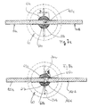
- Figure 4a and 4b show this joint surface in two views at the front end of the insert 40 for the fleece funnel 50. Swiveling the fleece funnel 50 in the direction ⁇ into the other angular position does not release the radially airtight seal between the fleece funnel and the band funnel; A radially airtight fleece guidance is achieved both in the swung-in and in the swung-out state.
- the radial tightness of the joint surfaces 41a, 41b on the Bearing surface 35 is adjustable.
- the upper part - above the Articular surface - can do this in the axial direction, especially in radial direction, in its relative position to the lower part to be changed.
- the basis for the adjustment is the fixed attached holder 20 in which the band funnel 30 is inserted is.
- the fleece funnel 50 is designed in two parts - with one inserted in the opposite direction of the fleece - Use, can be on a handle 51 the aforementioned Relative setting can be made.
- the fiber sliver is conveyed into the guide channel up to the clamping gap 100c through the fleece nozzle 50, the inner insert 40 and the band funnel 30, for which purpose the fleece funnel 50 is swung out and this is done manually by injector holes 34a, 34b, 64a, 64b on the band funnel according to FIG. 3 narrowed and held in the funnel mouth 50a sliver part F1.
- a short suction flow of the order of 500 msec is sufficient to convey the narrowed fiber sliver F1 to the clamping gap 100c with the least amount of compressed air, since the joint surface 35 and the bearing surfaces 41a, 41b of the inner insert 40 are radially airtight. Mechanical insertion aids are not required.
- a short angular momentum of duration T 2 is applied to the calender disks. It can switch itself on after a predetermined suction time T 1 , can be superimposed on it or can be initiated separately manually.
- the shape of the band funnel 30 can be seen more clearly in FIGS. 5a, 5b and 5c , where the direction and arrangement of the injector bores 34a, 34b in the band funnel are also shown enlarged. They open into a cylindrical channel 31 which forms the front end of the fleece channel. The cylindrical section 31 widens via a conical section 32 to the diameter of the fleece channel, which is predetermined by the inner insert 40. At the upper end of the cone, the bearing surfaces 35 are provided which correspond in their curvature to the joint surfaces 41a, 41b.
- the inclined injector bores 34a, 34b can run at an angle of approximately 45 ° with respect to the axis 200b of the band funnel insert 30; they can be offset in parallel to give the inserted sliver a twist and additional strength, as can be seen in FIG. 5d .
- a band funnel holder 60 according to FIGS. 6a, 6b, 6c has a central, approximately cylindrical opening 62, into which the band funnel insert 30 is inserted.
- an annular channel 63 which can be fed with compressed air from two or more cylindrical bores 64a, 64b, extends inwardly in the cylindrical opening.
- the compressed air introduced from the outside is introduced into the aforementioned inclined injector bores 34a, 34b when the band funnel insert 30 is inserted, in order to open into the cylindrical section 31 of the nonwoven channel, which lies close to the clamping gap 100c.
- Figures 6a and 6b illustrate the cylindrical beak 61 of the band funnel holder 60. It has a length L and a diameter, shown in the cross section of Figure 6b as width b.
- the beak 61 has two halves, since - as can be seen in FIG. 6c - it is slit on the side.
- a segment of the rotating calender disks 100a, 100b each engages in the two slots mentioned; this can also be clearly seen in FIG. 1 in the right half.
- the clamping gap 100c comes to rest, which according to FIGS. 7a and 7b can both be closed (clamping gap 100c) and by turning off the one calender disc 100b can be opened (open clamping gap 100d).
- A is used to guide this air first narrow channel section 65a on one side of the Calender disks or a second narrow channel section 65b on the other side of the calender discs, the one approximate have semicircular cross-sectional shape.
- the respective Channel is very narrow compared to the thickness d or Width b of the beak 61 or its inner wall, the immediate is adjacent to the side surface of the calender disk.
- the air not only passed the calender gap, but also clearly passed through the calender gap.
- the sliver is also immediately threaded through the calender nip and the calender disk 100b can then be delivered in order to have reached the operating position with the sliver threaded.
- the sealing surface part of the cover d
- the sealing surface is large enough in relation to the air resistance of the now enlarged passage channel, consisting of the channel segments 65a, 65b and the opened calender gap 100d, in order to prevent radial escape of guide air .
- an air pressure to be used 4 bar be called, which is tuned to one Channel diameter 31 of about 3.8mm in the band funnel 30 and about 8mm in the channel 45 of the insert 40 of the fleece funnel 50.
- an air pulse of approx. 500msec duration for safe insertion of the front part F1 of the Sliver up to the clamping gap 100c is sufficient.
- the length H1 of the manually narrowed sliver is the distance from Fleece funnel 50 to the clamping gap 100c and thus the length of the airtight fleece channel matched.
- the mentioned inwardly facing annular channel 63 can be in one alternative variant also on the insert 30 as to the outside pointing channel can be formed, for example by a circumferential notch. Both channels 63, 33 can also be provided to be in the assembled state of funnel 30 and Holder 60 together to form an annular channel.
- the band funnel holder 60 has between its upper cylindrical portion 62 and its beak portion 61 a Truncated cone section. With him or with that cylindrical section, it can be inserted into a carrier 20, that just above the calender discs 100a, 100b so is positioned that the beak portion of the holder 60 over the calender discs and the nip grips. On the carrier 20 is also the fleece nozzle 50 creating spacing bearing tabs 51 held pivotable. All parts of the nozzle system are interchangeable but still fixed in position.
- An apparatus and a method for Introducing at least one sliver part into the clamping line (100c) of (further) compacting calender rolls (100a, 100b) a sliver processing machine an air flow in the essentially loss-free due to two channel segments (65a, 65b) in the Area of the clamping gap (100c) of the pair of calender disks (100a, 100b) is initially passed to a part (F1) of the Sliver (F) in a nozzle guiding device (50, 40, 60, 30) without introducing mechanical insertion aids. So that will be Processing largely automated.
Landscapes
- Engineering & Computer Science (AREA)
- Mechanical Engineering (AREA)
- Textile Engineering (AREA)
- Spinning Or Twisting Of Yarns (AREA)
Claims (15)
- Procédé pour introduire au moins une partie d'un ruban de fibres dans la ligne de pincement (100c) de cylindres de calandre comprimants (100a, 100b) d'une machine textile travaillant du ruban de fibres, dans lequeldans le but d'obtenir l'introduction automatique de la partie (F1) d'abord raccourcie et rendue plus étroite du ruban de fibres (F) dans une installation de guidage de voile (50, 40, 60, 30).le bout avant du ruban de fibres est amené à une largeur plus petite (F1) et le tronçon du ruban de fibres plus étroit est raccourci à une longueur prédéterminée (H1);un courant d'air est dirigé essentiellement sans pertes à travers au moins deux sections de buses (30, 60) de l'élément de guidage du ruban de fibres à proximité des cylindres de calandre (100a, 100b) ou deux segments de canal (65a, 65b) dans le domaine de la fente de pincement (100c) de la paire de cylindres de calandre (100a, 100b);
- Procédé pour l'introduction automatique d'un ruban de fibres dans la ligne de pincement (100c) de cylindres de calandre comprimants (100a, 100b) dans lequel des canaux de guidage d'air (65a, 65b) situés à côté des cylindres de calandre (100a, 100b) et délimités de façon mécanique (61a, 61b) dirigent de l'air d'aspiration (air comprimé aspirant), à proximité immédiate de la fente de pincement (100c), mais en passant à côté de la fente de pincement (100c), pour introduire d'abord une partie du ruban de fibres total dans la fente de pincement (100c, 100d) ou jusqu'à proximité immédiate de celle-ci.
- Procédé pour l'introduction automatique d'un ruban de fibres dans la ligne de pincement (100c) de cylindres de calandre (100a, 100b) comprimants davantage, dans lequeld'abord une partie (F1) du ruban de fibres (F) est guidée d'au moins deux côtés par de l'air soufflant, cet air comprimé soufflant étant guidé en passant (61a, 61b) à côté de la paire de cylindres de calandre (100a, 100b) sans qu'il sorte auparavant de façon sensible transversalement de l'élément de guidage du ruban de fibres et sans qu'il soit ventilé.
- Procédé selon l'une des revendications, dans lequel la partie initiale (F1) du ruban de fibres comprend 10% à 30% de la largeur (F) totale du ruban de fibres.
- Procédé selon l'une des revendications mentionnées, dans lequel le ruban de fibres étiré est dévié transversalement par rapport à l'axe de guidage (200a, 200b) du ruban de fibres, par-dessus une rampe (50b) de l'entonnoir à voile (50) pivotée ou bien qui pivote automatiquement - dès que du ruban de fibres y arrive - dans le but de rendre plus étroit le ruban de fibres (F) à son bout avant et de créer une longueur prédéterminée (H1) de la partie initiale (F1) rendue plus étroite.
- Procédé selon l'une des revendications mentionnées dans lequela) le guidage de l'air depuis la première insertion d'une buse en tant qu'entonnoir à voile (50), pliant le ruban de fibres étiré, jusqu'à immédiatement avant les cylindres de calandre (100a, 100) et effectué sans pertes et sans que l'air passe ou s'échappe de façon transversale;b) le courant d'air n'est guidé qu'avec peu de pertes dans le domaine des cylindres de calandres (100a, 100b).
- Procédé selon la revendication 6, dans lequel les pertes dans le domaine des cylindres de calandre sont maintenues aussi faibles que possible par le faita) que des deux côtés des cylindres de calandre (100a, 100b) respectivement un bec (61a, 61b) présentant notamment une section demi-circulaire s'étend en direction de guidage de la voile constituant, à proximité du plan médian, entre les cylindres de calandre, un segment de canal (65a, 65b) de côté gauche et de côté droit ;b) que l'épaisseur (d) des becs (61a, 61b) à proximité immédiate des cylindres de calandre (100a, 100b) est choisie de telle sorte qu'une résistance suffisante contre le passage de l'air transversalement à l'axe de guidage (200b) du ruban de fibres est obtenue bien que les becs ne touchent pas les cylindres de calandre rotatifs.
- Procédé selon la revendication 7, dans lequel l'épaisseur (d) de la paroi des becs est choisie, au moins à l'endroit mentionné, de telle sorte qu'elle est nettement plus grande que la largeur ou la hauteur des segments de canal (65a, 65b), notamment qu'elle en constitue le double, transversalement à la direction de guidage du ruban de fibres.
- Procédé selon l'une des revendications susmentionnées, dans lequela) les segments de canal (65a, 65b) de part et d'autre des cylindres de calandre (100a, 100b) sont si étroits que la partie initiale (F1) du ruban de fibres (F) à introduire n'est pas menée de sorte à passer à côte des cylindres de calandre mais qu'elle s'arrête à la fente de pincement (100c) en attendant qu'un moment angulaire des cylindres de calandre (100a, 100b) la presse à travers la fente de pincement (100c); ou bien dans lequelb) la largeur (b) des moitiés de bec (61a, 61b) constituant les segments de canal (65a, 65b) est choisie si grande qu'aussi lorsque la fente de pincement (100d) est ouverte, notamment en cas de cylindres de calandre écartés, un recouvrement sans contact du cylindre de calandre d'une largeur de bec (d) est obtenu, dans le but de maintenir faible le débit d'air de guidage s'échappant de façon transversale et de mener la partie initiale (F1) du ruban de fibres jusque derrière l'endroit le plus étroit (100c) entre la paire de cylindres de calandre.
- Procédé selon l'une des revendications susmentionnées, dans lequel de l'air comprimé est introduit, depuis une espace annulaire (36) s'étendant autour de l'axe de guidage (200b) du ruban de fibres, et qui passe à travers des alésages inclinés (34a, 34b), dans le canal de guidage du ruban de fibres à l'endroit (31) présentant le plus petit diamètre.
- Procédé selon la revendication 10, dans lequel la section (31) du canal de guidage présentant le plus petit diamètre est disposée à proximité des cylindres de calandre.
- Buse d'amenée de calandre (30, 60) pour la mise en oeuvre du procédé selon l'une des revendications susmentionnées, dans laquellea) un canal (65a, 65b) au bout de sortie (61) de la buse est ouvert sur deux côtés afin de pouvoir recueillir respectivement un segment d'un cylindre de calandre (100a, 100b) respectif ;b) les moitiés de bec (61a, 61b) créées par suite de l'ouverture sur deux côtés sont conçues d'une longueur et d'une largeur (b) telles que leur guidage de l'air à guider dans le canal - après montage - passe latéralement aux cylindres de calandre (100a, 100b) afin d'amener le ruban de fibres à la fente de pincement (100c) des cylindres de calandre, au moins de manière à ce qu'il la touche.
- Buse d'amenée de calandre selon la revendication 12, dans laquelle au-dessus des moitiés de bec (61a, 61b) des alésages d'introduction (34a, 34b) sont prévus qui s'étendent latéralement dans le canal de guidage (31) et qui sont inclinés en direction de transport et les buses ne présentant pas d'orifices d'aération ou des alésages au-dessus des moitiés de bec (61a, 61b).
- Buse d'amenée de calandre selon la revendication 12 ou 13 qui est constituée de deux parties, présentant une insertion (30) située à l'intérieure, en forme d'entonnoir, avec un canal annulaire qui l'entoure, et un élément de retenue (60) recueillant l'insertion (30) et sur lequel les moitiés de bec (61a, 61b) sont montées.
- Buse d'amenée de calandre selon l'une des revendications 12 à 14, dans laquelle la largeur (b) des becs correspond environ au double ou au triple de la grosseur (d) d'une paroi intérieure du bec respectif avoisinant directement un cylindre de calandre respectif, et dans laquelle la longueur (L) des becs est plus grandes qu'à peu près la moitié du diamètre d'un cylindre de calandre.
Priority Applications (3)
| Application Number | Priority Date | Filing Date | Title |
|---|---|---|---|
| EP96102887A EP0736618B1 (fr) | 1995-04-07 | 1996-02-27 | Dispositif de guidage pour introduire un ruban de fibres dans la ligne de pincement des disques d'une calandre d'une machine de textile utilisant des rubans de fibres et un procédé d'introduction |
| DE59601205T DE59601205D1 (de) | 1995-04-07 | 1996-02-27 | Führungseinrichtung zum Einführen eines Faserbandes in die Klemmlinie von Kalanderscheiben einer faserbandverarbeitenden Textilmaschine und ein Verfahren zum Einführen |
| US08/622,213 US5680678A (en) | 1995-04-07 | 1996-03-27 | Process and guide system for the introduction of a fiber sliver into the nip line of calender disks of a fiber processing textile machine |
Applications Claiming Priority (4)
| Application Number | Priority Date | Filing Date | Title |
|---|---|---|---|
| DE29506107U | 1995-04-07 | ||
| DE29506107 | 1995-04-07 | ||
| DE29510871U | 1995-07-05 | ||
| DE29510871 | 1995-07-05 |
Publications (2)
| Publication Number | Publication Date |
|---|---|
| EP0736617A1 EP0736617A1 (fr) | 1996-10-09 |
| EP0736617B1 true EP0736617B1 (fr) | 1999-12-22 |
Family
ID=26057786
Family Applications (1)
| Application Number | Title | Priority Date | Filing Date |
|---|---|---|---|
| EP95114975A Expired - Lifetime EP0736617B1 (fr) | 1995-04-07 | 1995-09-22 | Transport pneumatique de mèche de fibres dans une calandre |
Country Status (2)
| Country | Link |
|---|---|
| EP (1) | EP0736617B1 (fr) |
| DE (1) | DE59507482D1 (fr) |
Cited By (1)
| Publication number | Priority date | Publication date | Assignee | Title |
|---|---|---|---|---|
| DE102006012335B4 (de) * | 2006-03-17 | 2015-07-09 | Rieter Ingolstadt Gmbh | Vliesführungsvorrichtung sowie Textilmaschine |
Families Citing this family (1)
| Publication number | Priority date | Publication date | Assignee | Title |
|---|---|---|---|---|
| DE19618642B4 (de) * | 1996-05-09 | 2007-07-19 | Rieter Ingolstadt Spinnereimaschinenbau Ag | Vliestrichter |
Family Cites Families (6)
| Publication number | Priority date | Publication date | Assignee | Title |
|---|---|---|---|---|
| CS179204B1 (en) | 1975-09-09 | 1977-10-31 | Miroslav Hanus | Equipment for thickening and transferring of textile fibres |
| FR2466527A1 (fr) | 1979-09-28 | 1981-04-10 | Alsacienne Constr Meca | Dispositif automatique d'introduction d'un voile de fibres textiles dans un coiler |
| DE3612133C2 (de) * | 1986-04-10 | 1995-02-16 | Truetzschler Gmbh & Co Kg | Bandführungskanal zwischen Ausgangswalzen und Kalanderwalzen an einer Spinnereivorbereitungsmaschine |
| DE3801688C2 (de) * | 1988-01-21 | 1999-04-08 | Truetzschler Gmbh & Co Kg | Bandführungskanal |
| DD290697A5 (de) | 1989-12-22 | 1991-06-06 | Hochschule F. Bauwesen Cottbus,De | Vorrichtung zum bearbeiten und herstellen von horizontal- und vertikalfugen in vertikalen oder stark geneigten oberflaechen |
| DE4235653C1 (de) | 1992-10-22 | 1994-03-17 | Rieter Ingolstadt Spinnerei | Vliestrichter eines textilen Streckwerkes |
-
1995
- 1995-09-22 EP EP95114975A patent/EP0736617B1/fr not_active Expired - Lifetime
- 1995-09-22 DE DE59507482T patent/DE59507482D1/de not_active Expired - Fee Related
Cited By (1)
| Publication number | Priority date | Publication date | Assignee | Title |
|---|---|---|---|---|
| DE102006012335B4 (de) * | 2006-03-17 | 2015-07-09 | Rieter Ingolstadt Gmbh | Vliesführungsvorrichtung sowie Textilmaschine |
Also Published As
| Publication number | Publication date |
|---|---|
| DE59507482D1 (de) | 2000-01-27 |
| EP0736617A1 (fr) | 1996-10-09 |
Similar Documents
| Publication | Publication Date | Title |
|---|---|---|
| EP3048191B1 (fr) | Buse d'un metier a filer a jet d'air et son procede d'ouverture | |
| DE3927739A1 (de) | Verfahren und vorrichtung zum falschdrallspinnen | |
| DE19543631C2 (de) | Verfahren und Vorrichtung zum Texturieren | |
| EP0736619B1 (fr) | Méthode et dispositif pour insérer du ruban devant la fente de pincement des disques de calandre | |
| EP0178466B1 (fr) | Procédé et dispositif pour la fabrication d'un fil | |
| DE3638110A1 (de) | Vorrichtung zum pneumatischen falschdrallspinnen | |
| DE3802413A1 (de) | Spinnmaschine mit einer vielzahl von nebeneinander liegenden spinnstellen | |
| CH655741A5 (de) | Streckeinrichtung fuer spinnmaschine. | |
| DE3631400A1 (de) | Verfahren und vorrichtung zum pneumatischen falschdrallspinnen | |
| EP0736617B1 (fr) | Transport pneumatique de mèche de fibres dans une calandre | |
| EP0736620B1 (fr) | Dispositif de guidage pour ruban de fibres pour une machine de textile utilisant des rubans de fibres et procédé pour son opération | |
| DE19618642B4 (de) | Vliestrichter | |
| DE102006028448A1 (de) | Kreuzleger | |
| EP0736618B1 (fr) | Dispositif de guidage pour introduire un ruban de fibres dans la ligne de pincement des disques d'une calandre d'une machine de textile utilisant des rubans de fibres et un procédé d'introduction | |
| EP0527355A1 (fr) | Procédé et dispositif pour l'introduction pneumatique d'une mèche de fibres dans un métier à filer | |
| WO2019115356A1 (fr) | Banc d'étirage et dispositif de serrage pour une machine à filer | |
| DE19945319B4 (de) | Vliestrichter | |
| DE19535300B4 (de) | Luftgestütztes Einführen von Faserband vor den Klemmspalt | |
| DE1532249B1 (de) | Vorrichtung zum Foerdern von pneumatisch kontinuierlich zugefuehrtem Schnittabak zu einer Strangzigarettenmaschine od.dgl. | |
| DE19535297A1 (de) | Kompakte Vliesführung ohne Führungsrohr und Austauschdüsen dafür | |
| DE19640855A1 (de) | Vorrichtung zum Zusammenfassen eines Vlieses zu einem Faserband am Ausgang von Streckwerken | |
| EP1654407B1 (fr) | Dispositif de guidage de non-tisse pour machine textile et machine textile | |
| DE3121866C2 (fr) | ||
| DE3416456C2 (de) | Verfahren und Vorrichtung zur Inbetriebnahme einer Friktionsspinnmaschine | |
| DE19535347A1 (de) | Schwenkbarer Vliestrichter für Vliesführung ohne Führungsrohr |
Legal Events
| Date | Code | Title | Description |
|---|---|---|---|
| PUAI | Public reference made under article 153(3) epc to a published international application that has entered the european phase |
Free format text: ORIGINAL CODE: 0009012 |
|
| AK | Designated contracting states |
Kind code of ref document: A1 Designated state(s): CH DE ES FR GB IT LI |
|
| 17P | Request for examination filed |
Effective date: 19960819 |
|
| 17Q | First examination report despatched |
Effective date: 19961113 |
|
| GRAG | Despatch of communication of intention to grant |
Free format text: ORIGINAL CODE: EPIDOS AGRA |
|
| GRAG | Despatch of communication of intention to grant |
Free format text: ORIGINAL CODE: EPIDOS AGRA |
|
| GRAH | Despatch of communication of intention to grant a patent |
Free format text: ORIGINAL CODE: EPIDOS IGRA |
|
| EL | Fr: translation of claims filed | ||
| GRAH | Despatch of communication of intention to grant a patent |
Free format text: ORIGINAL CODE: EPIDOS IGRA |
|
| GRAA | (expected) grant |
Free format text: ORIGINAL CODE: 0009210 |
|
| AK | Designated contracting states |
Kind code of ref document: B1 Designated state(s): CH DE ES FR GB IT LI |
|
| PG25 | Lapsed in a contracting state [announced via postgrant information from national office to epo] |
Ref country code: GB Free format text: LAPSE BECAUSE OF FAILURE TO SUBMIT A TRANSLATION OF THE DESCRIPTION OR TO PAY THE FEE WITHIN THE PRESCRIBED TIME-LIMIT Effective date: 19991222 Ref country code: FR Free format text: LAPSE BECAUSE OF FAILURE TO SUBMIT A TRANSLATION OF THE DESCRIPTION OR TO PAY THE FEE WITHIN THE PRESCRIBED TIME-LIMIT Effective date: 19991222 Ref country code: ES Free format text: THE PATENT HAS BEEN ANNULLED BY A DECISION OF A NATIONAL AUTHORITY Effective date: 19991222 |
|
| REG | Reference to a national code |
Ref country code: CH Ref legal event code: EP |
|
| REF | Corresponds to: |
Ref document number: 59507482 Country of ref document: DE Date of ref document: 20000127 |
|
| REG | Reference to a national code |
Ref country code: CH Ref legal event code: NV Representative=s name: KELLER & PARTNER PATENTANWAELTE AG |
|
| ITF | It: translation for a ep patent filed | ||
| EN | Fr: translation not filed | ||
| GBV | Gb: ep patent (uk) treated as always having been void in accordance with gb section 77(7)/1977 [no translation filed] |
Effective date: 19991222 |
|
| PLBE | No opposition filed within time limit |
Free format text: ORIGINAL CODE: 0009261 |
|
| STAA | Information on the status of an ep patent application or granted ep patent |
Free format text: STATUS: NO OPPOSITION FILED WITHIN TIME LIMIT |
|
| 26N | No opposition filed | ||
| PGFP | Annual fee paid to national office [announced via postgrant information from national office to epo] |
Ref country code: CH Payment date: 20011003 Year of fee payment: 7 |
|
| PG25 | Lapsed in a contracting state [announced via postgrant information from national office to epo] |
Ref country code: LI Free format text: LAPSE BECAUSE OF NON-PAYMENT OF DUE FEES Effective date: 20020930 Ref country code: CH Free format text: LAPSE BECAUSE OF NON-PAYMENT OF DUE FEES Effective date: 20020930 |
|
| REG | Reference to a national code |
Ref country code: CH Ref legal event code: PL |
|
| PG25 | Lapsed in a contracting state [announced via postgrant information from national office to epo] |
Ref country code: IT Free format text: LAPSE BECAUSE OF NON-PAYMENT OF DUE FEES;WARNING: LAPSES OF ITALIAN PATENTS WITH EFFECTIVE DATE BEFORE 2007 MAY HAVE OCCURRED AT ANY TIME BEFORE 2007. THE CORRECT EFFECTIVE DATE MAY BE DIFFERENT FROM THE ONE RECORDED. Effective date: 20050922 |
|
| PGFP | Annual fee paid to national office [announced via postgrant information from national office to epo] |
Ref country code: DE Payment date: 20061002 Year of fee payment: 12 |
|
| PG25 | Lapsed in a contracting state [announced via postgrant information from national office to epo] |
Ref country code: DE Free format text: LAPSE BECAUSE OF NON-PAYMENT OF DUE FEES Effective date: 20080401 |