EP0736643A1 - Elément isolant pour palier avec isolation phonique des parties de bâtiments - Google Patents
Elément isolant pour palier avec isolation phonique des parties de bâtiments Download PDFInfo
- Publication number
- EP0736643A1 EP0736643A1 EP96101326A EP96101326A EP0736643A1 EP 0736643 A1 EP0736643 A1 EP 0736643A1 EP 96101326 A EP96101326 A EP 96101326A EP 96101326 A EP96101326 A EP 96101326A EP 0736643 A1 EP0736643 A1 EP 0736643A1
- Authority
- EP
- European Patent Office
- Prior art keywords
- insulating body
- insulating
- element according
- building
- insulating element
- Prior art date
- Legal status (The legal status is an assumption and is not a legal conclusion. Google has not performed a legal analysis and makes no representation as to the accuracy of the status listed.)
- Withdrawn
Links
- 238000009413 insulation Methods 0.000 title claims description 64
- 238000011065 in-situ storage Methods 0.000 claims description 12
- 239000000463 material Substances 0.000 claims description 10
- 239000004570 mortar (masonry) Substances 0.000 claims description 9
- 230000002093 peripheral effect Effects 0.000 claims description 7
- 229920001971 elastomer Polymers 0.000 claims description 6
- 239000000806 elastomer Substances 0.000 claims description 6
- 239000013013 elastic material Substances 0.000 claims description 4
- 238000003860 storage Methods 0.000 claims description 4
- 239000011810 insulating material Substances 0.000 abstract description 2
- 230000007704 transition Effects 0.000 description 12
- 238000009415 formwork Methods 0.000 description 10
- 239000002390 adhesive tape Substances 0.000 description 4
- 230000015572 biosynthetic process Effects 0.000 description 2
- 238000010276 construction Methods 0.000 description 2
- 210000001503 joint Anatomy 0.000 description 2
- 238000007789 sealing Methods 0.000 description 2
- 239000000853 adhesive Substances 0.000 description 1
- 238000004026 adhesive bonding Methods 0.000 description 1
- 230000001070 adhesive effect Effects 0.000 description 1
- 238000005452 bending Methods 0.000 description 1
- 230000005540 biological transmission Effects 0.000 description 1
- 150000001875 compounds Chemical class 0.000 description 1
- 238000011109 contamination Methods 0.000 description 1
- 238000006073 displacement reaction Methods 0.000 description 1
- 239000006260 foam Substances 0.000 description 1
- 238000005187 foaming Methods 0.000 description 1
- 238000009434 installation Methods 0.000 description 1
- 239000012774 insulation material Substances 0.000 description 1
- 239000007788 liquid Substances 0.000 description 1
- 239000002184 metal Substances 0.000 description 1
- 238000000465 moulding Methods 0.000 description 1
- 238000009417 prefabrication Methods 0.000 description 1
Images


Classifications
-
- E—FIXED CONSTRUCTIONS
- E04—BUILDING
- E04B—GENERAL BUILDING CONSTRUCTIONS; WALLS, e.g. PARTITIONS; ROOFS; FLOORS; CEILINGS; INSULATION OR OTHER PROTECTION OF BUILDINGS
- E04B1/00—Constructions in general; Structures which are not restricted either to walls, e.g. partitions, or floors or ceilings or roofs
- E04B1/62—Insulation or other protection; Elements or use of specified material therefor
- E04B1/74—Heat, sound or noise insulation, absorption, or reflection; Other building methods affording favourable thermal or acoustical conditions, e.g. accumulating of heat within walls
- E04B1/82—Heat, sound or noise insulation, absorption, or reflection; Other building methods affording favourable thermal or acoustical conditions, e.g. accumulating of heat within walls specifically with respect to sound only
- E04B1/84—Sound-absorbing elements
-
- E—FIXED CONSTRUCTIONS
- E04—BUILDING
- E04F—FINISHING WORK ON BUILDINGS, e.g. STAIRS, FLOORS
- E04F11/00—Stairways, ramps, or like structures; Balustrades; Handrails
- E04F11/02—Stairways; Layouts thereof
- E04F11/022—Stairways; Layouts thereof characterised by the supporting structure
-
- E—FIXED CONSTRUCTIONS
- E04—BUILDING
- E04B—GENERAL BUILDING CONSTRUCTIONS; WALLS, e.g. PARTITIONS; ROOFS; FLOORS; CEILINGS; INSULATION OR OTHER PROTECTION OF BUILDINGS
- E04B1/00—Constructions in general; Structures which are not restricted either to walls, e.g. partitions, or floors or ceilings or roofs
- E04B1/62—Insulation or other protection; Elements or use of specified material therefor
- E04B1/74—Heat, sound or noise insulation, absorption, or reflection; Other building methods affording favourable thermal or acoustical conditions, e.g. accumulating of heat within walls
- E04B1/82—Heat, sound or noise insulation, absorption, or reflection; Other building methods affording favourable thermal or acoustical conditions, e.g. accumulating of heat within walls specifically with respect to sound only
- E04B2001/8254—Soundproof supporting of building elements, e.g. stairs, floor slabs or beams, on a structure
Definitions
- the invention relates to an insulation element for sound-absorbing storage of building parts such as stairs, ceilings and the like on building walls, consisting of an insulating body which can be inserted into the building wall and which is approximately cuboid and open on one side in the direction of the building part to be carried, which is approximately flush on its open side closes with the building wall surrounding it and is used to receive molded projections on the building part, which extend through the opening into the insulating body and rest there on a bearing arranged in the insulating body floor.
- Such insulation elements are used in particular when installing stairs and stair landings both for the storage of these parts of the building on the building walls that support them and also for structure-borne or impact sound insulation.
- the part of the building to be stored is spaced from the building wall by insulating strips in the joint area, so that no sound transmission is possible there either.
- the assembly is generally carried out in such a way that the insulating body is first positioned and then the insulating strips are laid at the predetermined positions in the joint area, leaving the insulating body openings free, into which the bearing projections of the part of the building are inserted.
- the insulation strips must be cut according to the size and position of the insulation body openings and laid around the insulation body so that they connect to it as flush as possible.
- the quality of the insulation in the transition area between the insulation strips and the insulation body therefore essentially depends on the care taken by the construction workers who cut the insulation strips.
- the present invention is based on the object of improving the insulating element of the type described in such a way that reliable insulation in the edge region of the insulating element is made available with less effort than previously and the formation of sound bridges by flowing concrete or mortar is ruled out.
- the insulating body has a protrusion towards the front of the building wall surrounding it and that this protrusion has at least one edge strip which adjoins at right angles and extends at least almost up to the upper edge of the part of the building and that this edge strip is made of soundproofing material consists.
- edge strip it is particularly expedient to choose the protrusion or the thickness of the edge strip in accordance with the thickness of the adjacent insulation strips, so that it adjoins it flush. Sidebar and insulation strips then form a flat surface, so that the unavoidable joint between the two parts can be closed in a simple manner, for example by an adhesive tape, a wide adhesive surface being provided by the edge strip according to the invention. This not only compensates for the inevitable tolerances when cutting the insulation strips, but also provides a hermetic seal for the joint between the skirting and the insulation strips. This eliminates the risk of sound bridges from flowing concrete or mortar.
- the integrally formed edge strip also has the advantage that it serves to space screed, tiles, mortar and the like from the adjacent building wall when it extends in an advantageous manner beyond the upper edge of the building part. As a rule, a protrusion of a few centimeters above the upper part of the building is sufficient.
- stairs made of in-situ concrete have the advantage that the lost formwork is prefabricated in the area which is formed by the insulating material, as a result of which the formwork to be produced on the construction site is reduced by a problematic formwork element.
- the edge strip In order to obtain a completely closed transition area near the upper edge of the opening, the edge strip must extend over at least the entire width of the insulating body and possibly also beyond.
- the principle for sealing the transition region near the upper edge can also advantageously be used to separate the lateral transition regions between
- a lower edge can also be formed on the insulation body, which, starting from the bottom edge of the opening, preferably extends down along the entire opening width parallel to the building wall and connects seamlessly to the side edges.
- the resulting skirting board frame is of course the variant that most reliably prevents sound bridges in the transition areas.
- the insulating element according to the invention can be completely dispensed with above the opening top edge, since this requires only a few centimeters of edge strips, the same also applies to any molded lower edge strips that must also be provided alongside the side edge strips, since it is the manufacturer's side Prefabrication of the insulation elements does not make it possible to adapt the entire required lateral extension of the side edge strip or the insulation strips to the respective circumstances.
- the lateral edge strips replace the critical lateral transition area between the insulation body and the insulation strip with a less problematic area away from the opening, which can be carried out tightly by bringing the side edge strips and adjacent insulation strips into abutting abutment and then connecting them with adhesive tapes become. Accordingly, the height of the side and lower edge strips can generally be made smaller than the height of the upper edge strip.
- the edge strips can be integrally formed on the insulating body, but both components do not have to be made of the same materials. However, good sound insulation and the possibility of being able to absorb displacement movements will be in the foreground for both components, which is why it is advisable, at least for the edge strips, to make them from soft, elastic material.
- edge strips as a separate element in the form of a collar which can be detachably connected to the insulating body by at least one plug connection.
- This collar then expediently also bears the overhang and on the latter the locking elements or the like are arranged, which are then inserted into the insulating body.
- the insulating body is surrounded by a recess shape, which is also approximately cuboid and is open on one side in the direction of the part of the building to be carried and serves to absorb the forces transmitted by the building wall, the material the recess shape is harder than the insulation body material and hard plastic or sheet metal is particularly recommended.
- the insulating body is only pushed into the recess shape subsequently, for example after striking or masonry.
- the mentioned recess shape can just as well be arranged within the insulating body, because even then the desired stiffening of the insulating body is given.
- the insulating body can have projections on at least two of its peripheral walls adjacent to the opening, which projections can be locked in place using appropriate means of the recess shape.
- These means can be formed, for example, by similar projections or notches, depending on the choice of material.
- the projections provided on the insulating body can, however, also serve to produce a positive connection between the insulating body and set in-situ concrete, mortar or masonry of the building wall if the use of a recess shape is not used. Otherwise, the recess shape can also even on at least two of their peripheral walls have projections for producing a positive connection with the building wall.
- the bearing is an elastomer bearing that is built into the bottom wall of the insulating body, for example by foaming or gluing.
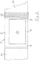
- an insulation element 1 is shown in particular for masonry, which consists of an approximately cuboidal insulation body 2 and a protrusion 3 integrally molded thereon with peripheral edge strips.
- the insulating body is designed to be open on one side in the direction of the part of the building to be carried, with an opening 4 into which bearing projections (see FIG. 5) of a part of the building to be supported extend.
- An elastomer bearing 5 is inserted at least in the insulating body floor, which serves to absorb the weight forces of the building part transmitted via the bearing projections.
- the insulating body floor itself can also serve as an elastomer bearing.
- the edge strips forming a frame extend perpendicular to the insulating body walls, which adjoin the opening 4. They consist of an upper edge strip 6, which extends from the upper edge of the opening along the adjacent building wall to at least the upper edge of the building part, of side edge strips 7 and 8, which are seamlessly connected to the upper edge strip 6, and a lower edge strip 9, the is in turn integrally formed on the side edge strips 7 and 8.
- the upper edge strip 6 is higher than the two side edge strips 7 and 8 or the lower edge strip 9. This is due to the fact that the upper edge strip is in addition to the spacing of the covering to be applied to the building part can be used by the adjacent building wall, as a result of which additional insulating strips in the form of an insulating plate or the like, which would then have to be cut out accordingly, can be completely dispensed with in the area of the upper opening edge.
- Such an insulation strip 50 or 51 is only required to the side of the two edge strips 7 and 8; the transition there is not critical, however, since the insulation strips connect flush to the insulation body via a simple butt joint connection and, if necessary, the butt joint can be hermetically sealed by an adhesive tape 52 applied to both parts.
- the lower edge strip 9 only projects downwards by an overhang corresponding to the wall thickness of the insulation body, since there the underside of the part of the building to be stored runs approximately flush with the upper edge of the elastomer bearing and through the lower edge strip 9 there is only a seamless connection the two side edges 7 and 8 are to be produced.
- the total height of the skirting board frame is approximately equal to the height of the insulation strips 50, 51.
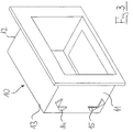
- Figure 3 shows an insulating element 10 corresponding to the insulating element from Figure 1, which differs from this only in that 13 projections 14 and 15 are provided on two lateral peripheral walls 11 and 12 of the insulating body, which for producing a positive connection of the insulating body with the in-situ concrete , Mortar or masonry of the adjacent building wall to serve. Otherwise, the insulation element 10 matches the insulation element 1.
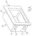
- FIGS. 4 and 5 show a further insulation element 20 similar to the insulation element 1 from FIG. 2, the insulation body 21 of which carries projections 24 and 25 on the lateral circumferential walls 22 and 23, which show a positive connection between the insulation body and a surrounding one, shown in FIG. 5 Allow recess shape 26.
- a recess form which consists of hard material and is used for bracing, is used in particular in building walls made of in-situ concrete and is attached to the formwork before pouring in-situ concrete, whereupon after the concrete has set and the formwork has been removed, the insulating body made of elastic material is inserted into it Recess form used and is locked in place over the projections.
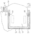
- FIG. 5 now shows the insulating element from FIG. 4 with the recess shape 26 surrounding it in the installed state in a sectional side view.
- the recess shape 26 is inserted into a building wall 30, while the insulation element carries a stair landing 40 which is supported on an elastomer bearing 27 of the insulation element via a bearing projection 41.
- the stair landing 40 is spaced from the building wall 30 by the upper edge 28 of the insulating element, so that no sound bridge can form there.
- the upper edge strip 28 also serves to acoustically isolate a floor covering 42, which is usually applied to the stair landing 40, from the building wall 30.
- FIGS. 4 and 5 also show that the edge strips 6, 7, 8 and 9 can form a separate frame which can be latched to the insulating body 21 by means of a plurality of plug connections 128.
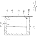
- Figures 6 and 7 show an alternative design.
- the upper edge 60 together with its projection 61 along horizontal dividing lines 62 and 63 are separated from the two side edges 64 and 65 and their projections.
- the lower ends of the lateral edge strips are separated from the lower edge strip 68 by corresponding dividing lines 66 and 67.
- the dividing lines run quite a bit into the cavity of the insulating body, for example up to the bending line indicated by reference number 69.
- the dividing lines mentioned in connection with the elastic material of the insulating body offer the possibility of folding the edge strips inwards into the cavity of the insulating body, as can be seen in FIG. 7.
- the Edges held by a cover plate 70 which simultaneously closes the entire cavity of the insulating body and thereby secures it against contamination from the outside.
- This cover plate expediently has projections or edge strips 70a, which can be locked or clamped on the recess shape 26.
- the folded edge strips can also be held in the interior of the insulating body in other ways, for example by means of adhesive tapes.
- FIGS. 6 and 7 The design shown in FIGS. 6 and 7 is particularly suitable for installing the insulating body in concrete walls, because the insulating body can then be easily attached to the formwork for the concrete wall without the edge strips being in the way.
- the recess shape 26 can thus be nailed directly to the formwork; after removal of the formwork, the cover plate 70 is removed, whereupon the edge strips automatically snap back into the position according to FIG. 6 due to their elasticity.
- the main advantage of the insulation element according to the invention is that additional insulation elements can be dispensed with, at least in the area of the upper edge of the opening, so that the laying of adjacent insulation strips is very much easier and that, in particular, the formation of sound bridges is prevented since there is no longer any concrete or mortar between the insulation bodies and insulation strips can penetrate.
- the invention also makes installation easier because adjacent insulation strips only still have to be butted with the edge strips, which eliminates the risk of faulty insulation material transitions in the critical area of the insulation body opening.
Landscapes
- Physics & Mathematics (AREA)
- Engineering & Computer Science (AREA)
- Architecture (AREA)
- Acoustics & Sound (AREA)
- Civil Engineering (AREA)
- Structural Engineering (AREA)
- Electromagnetism (AREA)
- Building Environments (AREA)
Applications Claiming Priority (2)
| Application Number | Priority Date | Filing Date | Title |
|---|---|---|---|
| DE1995113664 DE19513664A1 (de) | 1995-04-08 | 1995-04-08 | Dämmelement zur schalldämmenden Lagerung von Gebäudeteilen |
| DE19513664 | 1995-04-08 |
Publications (1)
| Publication Number | Publication Date |
|---|---|
| EP0736643A1 true EP0736643A1 (fr) | 1996-10-09 |
Family
ID=7759441
Family Applications (1)
| Application Number | Title | Priority Date | Filing Date |
|---|---|---|---|
| EP96101326A Withdrawn EP0736643A1 (fr) | 1995-04-08 | 1996-01-31 | Elément isolant pour palier avec isolation phonique des parties de bâtiments |
Country Status (2)
| Country | Link |
|---|---|
| EP (1) | EP0736643A1 (fr) |
| DE (1) | DE19513664A1 (fr) |
Families Citing this family (3)
| Publication number | Priority date | Publication date | Assignee | Title |
|---|---|---|---|---|
| DE102011009762A1 (de) | 2011-01-28 | 2012-08-02 | Schöck Bauteile GmbH | Bauelement zum Einbau in Trennfugen von Gebäuden |
| DE102012002168A1 (de) | 2012-02-07 | 2013-08-08 | Schöck Bauteile GmbH | Bauelement zum Einbau in Trennfugen von Gebäuden |
| DE102013107589A1 (de) | 2013-07-17 | 2015-01-22 | Schöck Bauteile GmbH | Vorrichtung zum schwingungsentkoppelten Verbinden eines ersten Gebäudeteils mit einem zweiten Gebäudeteil |
Citations (4)
| Publication number | Priority date | Publication date | Assignee | Title |
|---|---|---|---|---|
| CH596397A5 (en) * | 1976-09-24 | 1978-03-15 | Traugott Schoop | Car park building slabs shearing force absorption |
| DE9302685U1 (de) * | 1993-02-25 | 1993-05-13 | Franz Kohler GmbH, 7951 Eberhardzell | Haltevorrichtung für Trittplatten |
| EP0545854A1 (fr) * | 1991-11-29 | 1993-06-09 | Toni H. Erb | Mandrin d'attache travaillant en cisaillement |
| EP0685613A1 (fr) * | 1994-06-03 | 1995-12-06 | F.J. Aschwanden AG | Dispositif de reprise et de transfert d'efforts tranchants entre deux éléments de construction |
Family Cites Families (3)
| Publication number | Priority date | Publication date | Assignee | Title |
|---|---|---|---|---|
| DE3408556A1 (de) * | 1984-03-08 | 1985-09-12 | Eberhard Ing.(grad.) 7570 Baden-Baden Schöck | Trennelement fuer betonplatten |
| DE4102814C2 (de) * | 1991-01-31 | 1993-10-14 | Busse Marmor Und Betonwerke Gm | Schallschutzauflager |
| DE4319632A1 (de) * | 1993-05-06 | 1994-11-10 | Ewald Wachsmann | Auflagerelement für Bauelemente |
-
1995
- 1995-04-08 DE DE1995113664 patent/DE19513664A1/de not_active Ceased
-
1996
- 1996-01-31 EP EP96101326A patent/EP0736643A1/fr not_active Withdrawn
Patent Citations (4)
| Publication number | Priority date | Publication date | Assignee | Title |
|---|---|---|---|---|
| CH596397A5 (en) * | 1976-09-24 | 1978-03-15 | Traugott Schoop | Car park building slabs shearing force absorption |
| EP0545854A1 (fr) * | 1991-11-29 | 1993-06-09 | Toni H. Erb | Mandrin d'attache travaillant en cisaillement |
| DE9302685U1 (de) * | 1993-02-25 | 1993-05-13 | Franz Kohler GmbH, 7951 Eberhardzell | Haltevorrichtung für Trittplatten |
| EP0685613A1 (fr) * | 1994-06-03 | 1995-12-06 | F.J. Aschwanden AG | Dispositif de reprise et de transfert d'efforts tranchants entre deux éléments de construction |
Also Published As
| Publication number | Publication date |
|---|---|
| DE19513664A1 (de) | 1996-10-10 |
Similar Documents
| Publication | Publication Date | Title |
|---|---|---|
| DE69403902T2 (de) | Gussbetonwände | |
| EP0153660A2 (fr) | Elément de coffrage pour la construction à coffrage permanent | |
| DE19846599A1 (de) | Verfahren zum Aufbau von Trennwänden | |
| EP2853653B1 (fr) | Bande | |
| DE10262101B4 (de) | Dämmstoffplatte | |
| DE2455775A1 (de) | Dehnfugenleiste fuer estrichboeden | |
| EP0198157B1 (fr) | Liste d'un joint de dilatation en matière plastique, spécialement pour le joint de bordure d'une construction de plancher | |
| EP0736643A1 (fr) | Elément isolant pour palier avec isolation phonique des parties de bâtiments | |
| EP0611852B1 (fr) | Elément de paroi, en particulier élément de double paroi | |
| DE4340953C1 (de) | Rammschutz | |
| EP0506603B1 (fr) | Cellule monolithe et procédé pour sa fabrication | |
| DE20003380U1 (de) | Schalungsstein | |
| DE202009009095U1 (de) | Trockenbauplattensystem, insbesondere zum Bau einer Wand mit einer zurückspringenden geraden Kante | |
| DE29504707U1 (de) | Fugenplatte | |
| DE29816613U1 (de) | Dämmschicht für Treppen | |
| DE102022131325B4 (de) | Anordnung von Schalungselementen | |
| EP2692978A1 (fr) | Dispositif d'étanchéité pour un raccordement de porte étanche à l'humidité | |
| DE29908673U1 (de) | Formstein zur Herstellung von Mauerelementen | |
| DE29514456U1 (de) | Dämmelement zur schalldämmenden Lagerung von Gebäudeteilen | |
| DE9100092U1 (de) | Bauelement für die Erstellung von flächigen Gebäudeteilen und zugehöriger Montage-Bausatz zur Errichtung von Gebäuden | |
| EP0405108A1 (fr) | Bande de finition en forme de L | |
| DE9001808U1 (de) | Fertigbauelement | |
| DE2804637A1 (de) | Vorgefertigtes bauteil zur verwendung im bauwesen | |
| DE29724732U1 (de) | Holzbautafel | |
| DE29811283U1 (de) | Dachgaubenkonstruktion |
Legal Events
| Date | Code | Title | Description |
|---|---|---|---|
| PUAI | Public reference made under article 153(3) epc to a published international application that has entered the european phase |
Free format text: ORIGINAL CODE: 0009012 |
|
| AK | Designated contracting states |
Kind code of ref document: A1 Designated state(s): AT BE CH DE DK FR GB IT LI LU NL SE |
|
| 17P | Request for examination filed |
Effective date: 19961023 |
|
| 17Q | First examination report despatched |
Effective date: 19981211 |
|
| STAA | Information on the status of an ep patent application or granted ep patent |
Free format text: STATUS: THE APPLICATION IS DEEMED TO BE WITHDRAWN |
|
| 18D | Application deemed to be withdrawn |
Effective date: 19991209 |