EP0736665A2 - Bohrloch- und Tunnelausbau mit Stützwänden - Google Patents
Bohrloch- und Tunnelausbau mit Stützwänden Download PDFInfo
- Publication number
- EP0736665A2 EP0736665A2 EP96302315A EP96302315A EP0736665A2 EP 0736665 A2 EP0736665 A2 EP 0736665A2 EP 96302315 A EP96302315 A EP 96302315A EP 96302315 A EP96302315 A EP 96302315A EP 0736665 A2 EP0736665 A2 EP 0736665A2
- Authority
- EP
- European Patent Office
- Prior art keywords
- hole
- walls
- wall
- segment
- excavating
- Prior art date
- Legal status (The legal status is an assumption and is not a legal conclusion. Google has not performed a legal analysis and makes no representation as to the accuracy of the status listed.)
- Withdrawn
Links
- 238000010276 construction Methods 0.000 title claims abstract description 15
- 238000000034 method Methods 0.000 claims abstract description 49
- 230000003014 reinforcing effect Effects 0.000 claims description 13
- 239000004567 concrete Substances 0.000 claims description 12
- 239000000126 substance Substances 0.000 claims description 9
- 239000011440 grout Substances 0.000 claims description 7
- 239000000945 filler Substances 0.000 claims description 4
- 238000009412 basement excavation Methods 0.000 description 18
- 238000005553 drilling Methods 0.000 description 18
- 239000002689 soil Substances 0.000 description 10
- 238000005266 casting Methods 0.000 description 3
- 239000011150 reinforced concrete Substances 0.000 description 3
- 238000000605 extraction Methods 0.000 description 2
- 229920000642 polymer Polymers 0.000 description 2
- 239000011435 rock Substances 0.000 description 2
- 229910000278 bentonite Inorganic materials 0.000 description 1
- 239000000440 bentonite Substances 0.000 description 1
- SVPXDRXYRYOSEX-UHFFFAOYSA-N bentoquatam Chemical compound O.O=[Si]=O.O=[Al]O[Al]=O SVPXDRXYRYOSEX-UHFFFAOYSA-N 0.000 description 1
- 239000004568 cement Substances 0.000 description 1
- 239000000284 extract Substances 0.000 description 1
- 238000011010 flushing procedure Methods 0.000 description 1
- -1 gravel Substances 0.000 description 1
- 239000000463 material Substances 0.000 description 1
- 239000002184 metal Substances 0.000 description 1
- 238000000465 moulding Methods 0.000 description 1
- 230000002787 reinforcement Effects 0.000 description 1
- 238000007790 scraping Methods 0.000 description 1
- 238000000638 solvent extraction Methods 0.000 description 1
- XLYOFNOQVPJJNP-UHFFFAOYSA-N water Substances O XLYOFNOQVPJJNP-UHFFFAOYSA-N 0.000 description 1
Images


Classifications
-
- E—FIXED CONSTRUCTIONS
- E02—HYDRAULIC ENGINEERING; FOUNDATIONS; SOIL SHIFTING
- E02D—FOUNDATIONS; EXCAVATIONS; EMBANKMENTS; UNDERGROUND OR UNDERWATER STRUCTURES
- E02D17/00—Excavations; Bordering of excavations; Making embankments
-
- E—FIXED CONSTRUCTIONS
- E02—HYDRAULIC ENGINEERING; FOUNDATIONS; SOIL SHIFTING
- E02D—FOUNDATIONS; EXCAVATIONS; EMBANKMENTS; UNDERGROUND OR UNDERWATER STRUCTURES
- E02D29/00—Independent underground or underwater structures; Retaining walls
- E02D29/045—Underground structures, e.g. tunnels or galleries, built in the open air or by methods involving disturbance of the ground surface all along the location line; Methods of making them
-
- E—FIXED CONSTRUCTIONS
- E21—EARTH OR ROCK DRILLING; MINING
- E21D—SHAFTS; TUNNELS; GALLERIES; LARGE UNDERGROUND CHAMBERS
- E21D1/00—Sinking shafts
- E21D1/08—Sinking shafts while moving the lining downwards
-
- E—FIXED CONSTRUCTIONS
- E21—EARTH OR ROCK DRILLING; MINING
- E21D—SHAFTS; TUNNELS; GALLERIES; LARGE UNDERGROUND CHAMBERS
- E21D11/00—Lining tunnels, galleries or other underground cavities, e.g. large underground chambers; Linings therefor; Making such linings in situ, e.g. by assembling
- E21D11/04—Lining with building materials
- E21D11/08—Lining with building materials with preformed concrete slabs
-
- E—FIXED CONSTRUCTIONS
- E21—EARTH OR ROCK DRILLING; MINING
- E21D—SHAFTS; TUNNELS; GALLERIES; LARGE UNDERGROUND CHAMBERS
- E21D5/00—Lining shafts; Linings therefor
Definitions
- the present invention is generally in the field of excavations, e. g. construction of foundation elements, retaining walls and tunnels.
- Excavation of holes with support walls is required in several cases, particularly in loose soil or at excavations performed at watery environments, such as underwater excavations or excavations performed at high water tables. Holes with support walls may be useful also for obtaining higher strength of foundation elements or retaining walls.
- One method for constructing a hole with support walls is by first excavating the hole, placing an insert into the hole and then casting concrete into the space between the insert and the walls of the hole.
- This method is not suitable for excavating in a watery environment unless, the excavation is constantly filled with a substance such as Bentonite or suitable polymeric substances, which must then be subsequently pumped out during the concrete casting procedure.
- a further disadvantage of such a method lies in that the surface quality of the casted foundation elements or retaining walls (after removing the surrounding soil) is rough and for obtaining a smooth surface finish, treatment of the surface is necessary which again is a time and labor consuming procedure.
- Another known method for excavating holes with support walls is by excavating an opening in the ground of a size substantially larger than the size of the actual required size of the hole, then inserting precast reinforcing wall elements into the excavation and then filling back the removed soil into the gap between the walls of the excavation and the external faces of the reinforcing elements and pressing it.
- This method is complicated and time consuming and is restricted to substantially short and vertical excavations.
- a method for constructing an underground construction comprising:
- the excavation is substantially vertical and the construction, which comprises a hole having support walls, serves as a foundation element.
- the method comprises constructing a plurality of substantially vertical holes having support walls adjacent one another, these constructions serving as members in a retaining wall.
- the excavation is horizontal or slanted, to construct a tunnel with support walls, useful as ducts, as pipes for protecting cables, e.g. telephone or electric cables, contained therein, etc.
- the method according to either of the above embodiments may comprise also filling the space confined within the walls of the holes with a filler substance, such as concrete, reinforced concrete, gravel, soil, etc.
- a filler substance such as concrete, reinforced concrete, gravel, soil, etc.
- the construction is a vertical hole serving as a foundation element or a member in a retaining wall.
- the wall elements may comprise apertures for introducing concrete or the like into the interstice between the inner walls of the excavations and the external faces of the support walls.
- contact grout or concrete may be applied into the interstice directly by injecting it through tubes inserted therein.
- one side of all wall elements may have a shape or patents so that all such sides together form a uniform wall.
- the wall elements may consist of several elements which together form a tubular, e.g. cylindrical or prismatic, wall element.
- each wall element may consist of two members with a substantially U-like cross-sectional shape, which together form a tubular wall element.
- At least one side of the wall elements is removable.
- an inner surface of at least one side of the wall element is covered with a polymer substance.
- leading wall element may be identical or different to the other wall elements.
- the leading wall element comprises a wedge-like leading edge on at least one side thereof.
- the excavation is performed by an excavating equipment comprising pressure members adapted for applying force in a radial direction.
- the wall elements may be inserted and translocated within the hole by the use of such an excavation equipment.
- prefabricated wall elements for use in conjunction with the method of the invention.
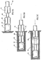
- FIGs. 1 and 2a-2g showing how a rectangular foundation element 2 is constructed according to the present invention.
- an initial hole segment 4 is excavated, for example by an excavating equipment 6 , such as that disclosed in PCT Patent Application WO 94/19272, comprising an excavating clamshell buckets 8 and surface clamping plates 10 , adapted for lateral extraction and retraction, the excavating equipment being operated and displaced into and out of the excavation by cables 12 and 13.
- an excavating equipment 6 such as that disclosed in PCT Patent Application WO 94/19272
- an excavating equipment 6 such as that disclosed in PCT Patent Application WO 94/19272
- an excavating clamshell buckets 8 and surface clamping plates 10 adapted for lateral extraction and retraction, the excavating equipment being operated and displaced into and out of the excavation by cables 12 and 13.
- various other excavating equipment may also be used.
- the surface clamping plates 10 apply lateral pressure on the inner wall of a portion 14 of the initial hole segment 4 , as can be seen in Fig. 2B, whereby the walls of the portion 14 assume a final shape corresponding to the external shape and size of a rectangular leading reinforcing wall element 16 .
- a leading wall element 16 is inserted into the formed portion 14 , as shown in Fig. 2C.
- the wall elements are typically prefabricated elements, the nature of which will be explained in more detail below.
- the next step in constructing the foundation element is digging a further hole segment 18 and then the pressure plates 10 expand and form the walls of segment 18 so that they assume a shape and size corresponding to the external shape and size of the reinforcing wall elements.
- a trailing reinforcing wall element 20 is introduced into the initial hole segment 4 as shown in Fig. 2E.
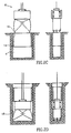
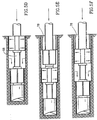
- FIG. 3 and 4A-4G of the drawings illustrating how a cylindrical hole 30 with a support wall is constructed according to the method of the present invention.
- an initial bore segment 32 is drilled, for example by using the drilling equipment 34 as disclosed in GB Patent No. 2176519, comprising a drilling tool such as an auger 36 connected to a drive (not shown) and further comprising clamping shells 38 having the shape of cylindrical segments, adapted for applying radial pressure on the walls of the bore and pressing the ground.
- a drilling tool such as an auger 36 connected to a drive (not shown)
- clamping shells 38 having the shape of cylindrical segments, adapted for applying radial pressure on the walls of the bore and pressing the ground.
- auger 36 also a bucket or any other drilling tool adapted to the soil conditions may be used.
- the drilling equipment is introduced and removed from the bore by a hoisting cable 40 .
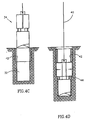
- the drilling equipment 34 is again lowered into the bore through the confined space of leading wall element 42 and a further hole segment 44 is then excavated as shown in Fig. 4D.
- the further hole segment 44 is formed by the clamping shells 38 to the shape and size corresponding to the external shape and size of the reinforcing wall elements 42 (Fig. 4D).
- the leading wall element 42 drops into the further hole segment 44 and after the drilling equipment 34 is withdrawn from the bore, a trailing wall element 46 is inserted into the initial bore and over the leading wall element 42 , as shown in Fig. 4E.
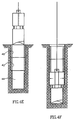
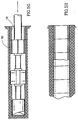
- FIGs. 5A - 5H it will be explained how a horizontal tunnel with support walls may be constructed according to the present invention. however, it should be obvious that tunnel construction in accordance with the invention is not restricted to horizontal and may obviously also be diagonal.
- tunnels are substantially horizontal holes in which gravitation forces do not assist in excavating or in inserting the wall elements and thus, specialized equipment is required.
- Drilling equipment 60 comprises a drilling end 62 (which may be for example a drilling bit, an auger or a bucket drill or any other drilling tool adapted to the specific ground conditions; in case of a drilling bit continuous drilling operations may be obtained by the aid of a flushing system) attached by a first shaft 64 to a drive (not shown) and further comprising a first set of clamping shells 66 linked by a second shaft 68 to a second set of clamping shells 70 , both sets of clamping shells capable of radially expanding and retracting.
- the shafts 64 and 68 are axially retractable.
- an initial hole segment 74 is drilled (Figs. 5A,5B).
- the first set of clamping shells 66 are radially expanded whereby they clamp against the inner wall of the hole, followed by extraction of the first shaft 64 , whereby the drilling end 62 is urged into the soil and further drilling is performed (Fig. 5C).
- clamp shells 66 contract and shaft 64 retracts.
- clamp shells 70 radially expand and clamp against the wall of the hole and the second shaft 68 extracts (Fig. 5D).
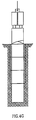
- the drilling equipment is removed from the hole and a leading wall element 78 is inserted into the initial hole segment 74 .
- the design of the clamp shells 66 and 70 is such that inserting the wall elements 78 and 80 may be performed by the aid of the clamp shells clampingly gripping the wall elements at their inner surfaces and advancing them into the hole (as illustrated in Fig. 5G).
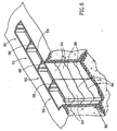
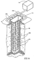
- Fig. 6 of the drawings illustrates a retaining wall 90 constructed of plurality of vertical reinforced holes 92 , each consisting of a plurality of wall elements 94 and constructed as explained in connection with Figs. 1 and 2A-2G.
- adjacent wall elements 94 above one another are fixed to one another by a male-female arrangement 96
- adjacent wall elements near one another are fixed by other male-female arrangement 98 .
- a male-female arrangement 100 is also suitable for fixing two cylindrical wall elements 102 and 104 above one another, each such wall element comprising at a bottom edge thereof several cut-outs 106 whereas the opposed, top end of each of the elements comprises projections 108 of a shape and size adapted to blend with the cut-outs of a trailing wall element.
- Fig. 8 of the drawing illustrates another method for fixing adjacent, neighboring wall elements of a retaining wall.
- each of the wall elements 112 and 114 of holes 116 and 118 respectively, has U-like shaped sides 120 , whereas when the two neighboring wall elements are constructed adjacent one another with the U-shaped edges facing one another, there is created a cavity 122 .
- This cavity may be reinforced by cement cast or by soil, rocks, etc., whereby lateral movement between the adjacent reinforcement holes 116 and 118 is prevented.
- Figs. 9 and 10 show a rectangular leading wall element 128 comprising a wedge-like edge 130 at two opposed edges thereof. This arrangement is useful in blazing the trail of the leading wall element by scraping the soil projecting into a hole segment which may obstruct the advancing of the wall elements.
- the wedge-like edge is also operating as a guide for the excavating tool while being extracted from the hole.
- the confined space within the walls of the hole may be filled with a filler substance which may be, for example plain or reinforced concrete, soil which has been removed during excavating the hole, rocks, etc.
- a foundation element or a retaining wall is later to be exposed by removing the surrounding soil, it may at times be desired to have one or more sides of the construction with a decorative pattern or design, or simply obtain a good surface quality which will require no further operations thereon.
- the rectangular wall element 138 of Fig.11 comprises a removable wall 140 secured to the element by locking nuts 142 , the inner surface of the wall 140 comprising a molding pattern.
- the arrangement is such that after constructing the hole and casting concrete in it, the ground surrounding the foundation element or retaining wall is excavated and the removable walls 140 (all facing the same side) are removed, exposing a concrete wall having the negative design of the decorative pattern of the inner surface of the removed wall.
- the inner surface of at least the removable wall 140 may be coated with a polymeric substance, which will ensure a smooth concrete surface.
- Fig. 12 illustrates how a tubular wall element 146 may be constructed of several segments, in the present case of two substantially U-like shaped elements 148 and 150, with locking members 152 for attaching the elements to one another.
- Such elements are useful for example for constructing a retaining wall, where the partitioning walls between neighboring wall elements are removed, whereby a continuous wall is obtained.
- wall elements 160 as seen in Fig. 13 may be used, such elements comprise a plurality of side apertures 162 . After inserting the wall elements into the hole, concrete is introduced into the space confined within the walls, which then penetrates into said interstice through the apertures 162 .
- the contact between the construction and the surrounding ground may also be improved by applying contact grout directly into the interstice 166 as shown in Fig. 14, by a plurality of injecting tubes 168 introduced into the interstice 166 , each tube comprising a plurality of nozzles 170 .
- the tubes 168 are connected to a central tube 172 receiving pressurized contact grout from a pressure unit 174 whereby the contact grout is forcefully injected into to the interstice 166 .
- Excavations for constructing the holes according to the present invention may be performed by a variety of excavating means, however, it should be noted that an important feature of the excavating equipment is its ability to apply lateral pressure onto the walls of the hole for forming them into the shape and size corresponding to that of the external shape and size of the reinforcing walls, whereby the walls of the hole are pressed.
- the wall elements are prefabricated elements manufactured at a large variety of sizes and of various materials, e.g. plain or reinforced concrete, polymers, metal or various combinations thereof.
Landscapes
- Engineering & Computer Science (AREA)
- Mining & Mineral Resources (AREA)
- Life Sciences & Earth Sciences (AREA)
- General Life Sciences & Earth Sciences (AREA)
- Structural Engineering (AREA)
- Geology (AREA)
- Geochemistry & Mineralogy (AREA)
- Civil Engineering (AREA)
- Paleontology (AREA)
- General Engineering & Computer Science (AREA)
- Mechanical Engineering (AREA)
- Architecture (AREA)
- Environmental & Geological Engineering (AREA)
- Earth Drilling (AREA)
- Bulkheads Adapted To Foundation Construction (AREA)
Applications Claiming Priority (2)
| Application Number | Priority Date | Filing Date | Title |
|---|---|---|---|
| IL11326295 | 1995-04-05 | ||
| IL11326295A IL113262A0 (en) | 1995-04-05 | 1995-04-05 | Construction of holes and tunnels having support walls |
Publications (2)
| Publication Number | Publication Date |
|---|---|
| EP0736665A2 true EP0736665A2 (de) | 1996-10-09 |
| EP0736665A3 EP0736665A3 (de) | 1997-11-19 |
Family
ID=11067320
Family Applications (1)
| Application Number | Title | Priority Date | Filing Date |
|---|---|---|---|
| EP96302315A Withdrawn EP0736665A3 (de) | 1995-04-05 | 1996-04-01 | Bohrloch- und Tunnelausbau mit Stützwänden |
Country Status (3)
| Country | Link |
|---|---|
| EP (1) | EP0736665A3 (de) |
| JP (1) | JPH08284581A (de) |
| IL (1) | IL113262A0 (de) |
Cited By (1)
| Publication number | Priority date | Publication date | Assignee | Title |
|---|---|---|---|---|
| GB2447622A (en) * | 2007-01-10 | 2008-09-24 | Martello Piling Ltd | Method of excavating a non-circular shaft |
Family Cites Families (10)
| Publication number | Priority date | Publication date | Assignee | Title |
|---|---|---|---|---|
| DE936561C (de) * | 1954-01-27 | 1955-12-15 | Holzmann Philipp Ag | Verfahren fuer das Abteufen von Schaechten |
| DE2709114A1 (de) * | 1977-03-02 | 1978-09-07 | Zueblin Ag | Verfahren zur herstellung von unterirdischen transportwegen grossen durchmessers |
| US4227583A (en) * | 1978-11-13 | 1980-10-14 | Wirth Maschinen-Und Bohrgerate-Fabrik | Method and apparatus for sinking shafts |
| GB2094860B (en) * | 1981-03-14 | 1985-01-23 | Dunlop Ltd | Lining of tubular structures |
| GB2099479A (en) * | 1981-05-13 | 1982-12-08 | Charcon Tunnels Ltd | Improvements in or relating to arcuate tunnel lining segments |
| DE3125274C2 (de) * | 1981-06-24 | 1984-05-17 | Philipp Holzmann Ag, 6000 Frankfurt | Verfahren zum Bau von kurvenförmig verlaufenden Tunneln nach dem Rohrvorpreßverfahren und dazu geeignete Rohre |
| GB8317347D0 (en) * | 1983-06-27 | 1983-07-27 | Mini Tunnels Int Ltd | Tunnelling and relining |
| DE3416287A1 (de) * | 1984-05-03 | 1985-11-07 | Ernst 7270 Nagold Wackenhut | Verfahren zur herstellung eines fundamentes |
| IL75160A0 (en) * | 1985-05-10 | 1985-09-29 | Yitzhaq Lipsker | Soil drilling equipment |
| DE3660932D1 (en) * | 1986-04-25 | 1988-11-17 | Koeckelberg Sa | Tunnel construction process |
-
1995
- 1995-04-05 IL IL11326295A patent/IL113262A0/xx unknown
-
1996
- 1996-04-01 EP EP96302315A patent/EP0736665A3/de not_active Withdrawn
- 1996-04-02 JP JP8101998A patent/JPH08284581A/ja active Pending
Cited By (1)
| Publication number | Priority date | Publication date | Assignee | Title |
|---|---|---|---|---|
| GB2447622A (en) * | 2007-01-10 | 2008-09-24 | Martello Piling Ltd | Method of excavating a non-circular shaft |
Also Published As
| Publication number | Publication date |
|---|---|
| IL113262A0 (en) | 1995-07-31 |
| EP0736665A3 (de) | 1997-11-19 |
| JPH08284581A (ja) | 1996-10-29 |
Similar Documents
| Publication | Publication Date | Title |
|---|---|---|
| US4453861A (en) | Trench walls and method for constructing same | |
| US11692324B2 (en) | Wall element system and method and apparatus for constructing shoring walls | |
| CA1207542A (en) | Method and apparatus for constructing reinforced concrete walls in the earth | |
| US6749372B2 (en) | Underground shell-pile continuous wall job practice and its special drill | |
| EP0736665A2 (de) | Bohrloch- und Tunnelausbau mit Stützwänden | |
| EP0580926A1 (de) | Dichtung für Ortbetonschlitzwände und Verfahren zur Herstellung der Schlitzwände | |
| JPH06306853A (ja) | 地下構造物の施工法 | |
| WO1988009849A1 (en) | Reinforcement for continuously-cast concrete walls | |
| CN109653193B (zh) | 逆作地下连续墙施工方法 | |
| EP0337680A2 (de) | Tunnelbau | |
| CN115262533B (zh) | 免接头地下连续墙及其施工方法 | |
| JP3355282B2 (ja) | 透水用矢板とこの矢板を用いた透水部を有する連続地中壁の構築方法 | |
| CN110637126B (zh) | 隔水墙 | |
| KR100556976B1 (ko) | 구조물 단위체를 이용한 개량된 메서 쉴드공법 | |
| JP3766423B2 (ja) | 擁壁の構築方法 | |
| EP1964981A1 (de) | Verstärkungselemente für Ortbetonwände und Verfahren zur Aushebung von Ortbetonwänden | |
| JPH06336725A (ja) | 地中連続壁工法、それに用いる掘削機、鉄筋籠及び地中連続壁 | |
| DE3716750A1 (de) | Verfahren zum herstellen und niederbringen von gruendungsbauwerken | |
| JPH0723084U (ja) | 地下構造物用コンクリ─ト函体 | |
| JPH05140940A (ja) | 大深度掘削に伴う土留め工法 | |
| JP2000220158A (ja) | 水底トンネルの構築工法 | |
| KR20200101637A (ko) | 파일의 연속 시공을 위한 보조 형틀장치 | |
| AU1803688A (en) | Reinforcement for continuously-cast concrete walls | |
| JPH0428044B2 (de) | ||
| JPH01178675A (ja) | 既設構造物下への地下室の構築方法 |
Legal Events
| Date | Code | Title | Description |
|---|---|---|---|
| PUAI | Public reference made under article 153(3) epc to a published international application that has entered the european phase |
Free format text: ORIGINAL CODE: 0009012 |
|
| AK | Designated contracting states |
Kind code of ref document: A2 Designated state(s): DE FR GB IT |
|
| PUAL | Search report despatched |
Free format text: ORIGINAL CODE: 0009013 |
|
| AK | Designated contracting states |
Kind code of ref document: A3 Designated state(s): DE FR GB IT |
|
| RHK1 | Main classification (correction) |
Ipc: E21D 1/08 |
|
| STAA | Information on the status of an ep patent application or granted ep patent |
Free format text: STATUS: THE APPLICATION IS DEEMED TO BE WITHDRAWN |
|
| 18D | Application deemed to be withdrawn |
Effective date: 19970410 |