EP0736732A1 - Bruleur a tube rayonnant et procede de fonctionnement de tels bruleurs a tube rayonnant - Google Patents
Bruleur a tube rayonnant et procede de fonctionnement de tels bruleurs a tube rayonnant Download PDFInfo
- Publication number
- EP0736732A1 EP0736732A1 EP95932212A EP95932212A EP0736732A1 EP 0736732 A1 EP0736732 A1 EP 0736732A1 EP 95932212 A EP95932212 A EP 95932212A EP 95932212 A EP95932212 A EP 95932212A EP 0736732 A1 EP0736732 A1 EP 0736732A1
- Authority
- EP
- European Patent Office
- Prior art keywords
- combustion
- radiant tube
- burner
- fuel
- air
- Prior art date
- Legal status (The legal status is an assumption and is not a legal conclusion. Google has not performed a legal analysis and makes no representation as to the accuracy of the status listed.)
- Granted
Links
Images


Classifications
-
- F—MECHANICAL ENGINEERING; LIGHTING; HEATING; WEAPONS; BLASTING
- F23—COMBUSTION APPARATUS; COMBUSTION PROCESSES
- F23L—SUPPLYING AIR OR NON-COMBUSTIBLE LIQUIDS OR GASES TO COMBUSTION APPARATUS IN GENERAL ; VALVES OR DAMPERS SPECIALLY ADAPTED FOR CONTROLLING AIR SUPPLY OR DRAUGHT IN COMBUSTION APPARATUS; INDUCING DRAUGHT IN COMBUSTION APPARATUS; TOPS FOR CHIMNEYS OR VENTILATING SHAFTS; TERMINALS FOR FLUES
- F23L15/00—Heating of air supplied for combustion
- F23L15/02—Arrangements of regenerators
-
- F—MECHANICAL ENGINEERING; LIGHTING; HEATING; WEAPONS; BLASTING
- F23—COMBUSTION APPARATUS; COMBUSTION PROCESSES
- F23D—BURNERS
- F23D14/00—Burners for combustion of a gas, e.g. of a gas stored under pressure as a liquid
- F23D14/12—Radiant burners
-
- F—MECHANICAL ENGINEERING; LIGHTING; HEATING; WEAPONS; BLASTING
- F23—COMBUSTION APPARATUS; COMBUSTION PROCESSES
- F23C—METHODS OR APPARATUS FOR COMBUSTION USING FLUID FUEL OR SOLID FUEL SUSPENDED IN A CARRIER GAS OR AIR
- F23C3/00—Combustion apparatus characterised by the shape of the combustion chamber
- F23C3/002—Combustion apparatus characterised by the shape of the combustion chamber the chamber having an elongated tubular form, e.g. for a radiant tube
-
- F—MECHANICAL ENGINEERING; LIGHTING; HEATING; WEAPONS; BLASTING
- F23—COMBUSTION APPARATUS; COMBUSTION PROCESSES
- F23D—BURNERS
- F23D14/00—Burners for combustion of a gas, e.g. of a gas stored under pressure as a liquid
- F23D14/20—Non-premix gas burners, i.e. in which gaseous fuel is mixed with combustion air on arrival at the combustion zone
- F23D14/22—Non-premix gas burners, i.e. in which gaseous fuel is mixed with combustion air on arrival at the combustion zone with separate air and gas feed ducts, e.g. with ducts running parallel or crossing each other
-
- F—MECHANICAL ENGINEERING; LIGHTING; HEATING; WEAPONS; BLASTING
- F23—COMBUSTION APPARATUS; COMBUSTION PROCESSES
- F23D—BURNERS
- F23D14/00—Burners for combustion of a gas, e.g. of a gas stored under pressure as a liquid
- F23D14/46—Details
- F23D14/66—Preheating the combustion air or gas
-
- F—MECHANICAL ENGINEERING; LIGHTING; HEATING; WEAPONS; BLASTING
- F23—COMBUSTION APPARATUS; COMBUSTION PROCESSES
- F23C—METHODS OR APPARATUS FOR COMBUSTION USING FLUID FUEL OR SOLID FUEL SUSPENDED IN A CARRIER GAS OR AIR
- F23C2900/00—Special features of, or arrangements for combustion apparatus using fluid fuels or solid fuels suspended in air; Combustion processes therefor
- F23C2900/06041—Staged supply of oxidant
-
- F—MECHANICAL ENGINEERING; LIGHTING; HEATING; WEAPONS; BLASTING
- F23—COMBUSTION APPARATUS; COMBUSTION PROCESSES
- F23C—METHODS OR APPARATUS FOR COMBUSTION USING FLUID FUEL OR SOLID FUEL SUSPENDED IN A CARRIER GAS OR AIR
- F23C2900/00—Special features of, or arrangements for combustion apparatus using fluid fuels or solid fuels suspended in air; Combustion processes therefor
- F23C2900/09002—Specific devices inducing or forcing flue gas recirculation
-
- F—MECHANICAL ENGINEERING; LIGHTING; HEATING; WEAPONS; BLASTING
- F23—COMBUSTION APPARATUS; COMBUSTION PROCESSES
- F23D—BURNERS
- F23D2900/00—Special features of, or arrangements for burners using fluid fuels or solid fuels suspended in a carrier gas
- F23D2900/00014—Pilot burners specially adapted for ignition of main burners in furnaces or gas turbines
-
- Y—GENERAL TAGGING OF NEW TECHNOLOGICAL DEVELOPMENTS; GENERAL TAGGING OF CROSS-SECTIONAL TECHNOLOGIES SPANNING OVER SEVERAL SECTIONS OF THE IPC; TECHNICAL SUBJECTS COVERED BY FORMER USPC CROSS-REFERENCE ART COLLECTIONS [XRACs] AND DIGESTS
- Y02—TECHNOLOGIES OR APPLICATIONS FOR MITIGATION OR ADAPTATION AGAINST CLIMATE CHANGE
- Y02E—REDUCTION OF GREENHOUSE GAS [GHG] EMISSIONS, RELATED TO ENERGY GENERATION, TRANSMISSION OR DISTRIBUTION
- Y02E20/00—Combustion technologies with mitigation potential
- Y02E20/34—Indirect CO2mitigation, i.e. by acting on non CO2directly related matters of the process, e.g. pre-heating or heat recovery
Definitions
- the present invention relates to a radiant tube burner and a combustion method thereof used in industrial heating furnaces and heat treatment furnaces for heating materials.
- any of the above combustion schemes is difficult to execute since a fuel nozzle is generally inserted in a heat-resistant alloy radiant tube of as small caliper as 90-200 mm to form an air throat.
- a fuel nozzle is generally inserted in a heat-resistant alloy radiant tube of as small caliper as 90-200 mm to form an air throat.
- provision of a secondary fuel nozzle for injecting a secondary fuel is required downstream of the primary combustion, it is extremely difficult to have a secondary fuel nozzle provided outside or inside the primary combustion chamber in a narrow space of the radiant tube.
- to employ a double cylinder structure is indispensable to assure a passage for supplying a secondary air downstream of the primary combustion zone, but the placement thereof is extremely difficult in the radiant tube with a restricted space.
- the reduction principle of NOx in each of the above-mentioned combustion methods is difficult to make the best of.
- Japanese Patent Application Laid-Open No. 62-242711 discloses that addition of water in a burner enables the generation of NOx to be reduced.
- Japanese Patent Application Laid-Open No. 63-116011 discloses that a high-load combustion based on a turning flow of primary air permits a good and stable combustion and a soft two-stage combustion in a radiant tube enables the generation of NOx to be reduced.
- Japanese Patent Application Laid-Open No. 3-11202 discloses that, provision of a Venturi mechanism and recirculation of exhaust gas under control of flow rate enable the generation of NOx to be reduced.
- each of the above-mentioned combustion methods is difficult to implement because a burner gun is inserted into a radiant tube of relatively small diameter. That is, with the fuel two-stage method, for allowing a secondary fuel to burn downstream after combustion of a primary fuel, provision of a fuel supply passage outside (or inside) the primary combustion chamber is necessary which extends to the secondary fuel injection port. And with the air multi-stage combustion method, to lead a secondary air to downstream of a primary combustion region is necessary and a double-structured air passage must be provided. For these reasons, implementation of the individual combustion methods mentioned above requires a large-sized and complex-structured burner itself, so that the above combustion methods were hardly applicable to a radiant tube burner.
- preheated-air temperature was about 500°C according to a conventional recuperator method
- the method of Japanese Patent Publication No. 2-23950, relevant to the art wherein the alternate combustion mentioned above made it possible to obtain a preheated-air temperature of more than 900°C has a problem that, as compared with a conventional method, a considerable rise in the temperature of preheated air elevates the flame temperature and increases the quantity of generated NOx.
- the present authors found that the quantity of generated NOx is inversely proportional to the flow velocity of combustion air (cf. FIG. 1).
- the temperature of preheated air obtained by the recuperator method applied to a conventional radiant tube burner is on the order of 500°C and this preheated air has no ignition energy sufficient for COG (Coke Oven Gas; ignition temperature on the order of 500 - 600°C) and LNG (ignition temperature on the order of 550 - 650°C) to be used as fuel for a radiant tube burner.
- COG Coke Oven Gas
- LNG ignition temperature on the order of 550 - 650°C
- a conventional burner for a low-NOx combustion method wherein the flow velocity of combustion air is set to about 50 - 60 times the combustion speed of fuel, a intra is applied to a furnace in which a high-temperature preheated air on the order of 930°C is obtained at an intra-furnace temperature of 900°C and a coke furnace gas mixed with fuel gas and air in the air ratio of about 1.3 at one time is employed as a fuel gas for combustion.
- exhaust gas at the first stage is allowed to undergo perfect combustion at the second stage.
- FIG. 2 shows the experimental results on the relation between pre-heated air temperature and the NOx content in exhaust gas obtained by the inventors in such a two-stage combustion method, which reveals that a low NOx combustion cannot be sufficiently fulfilled in the two-stage combustion.
- a basic reason for a high combustion temperature in combustion of a radiant tube burner is that the highest region in combustion temperature with an air ratio of about 0.95 - 1.00 is localized.
- the inventors compared and examined a case of combustion at air ratios of 1.4 and 4.0 in a premix combustion that a premixed gas of fuel and air is allowed to burn and a case of combustion at air ratios of 1.4 and 4.0 in a diffuse combustion that separately supplied fuel and air are allowed to burn.
- FIG. 4 it is found from the results that, whereas the maximum combustion temperature in the combustion region varies substantially for a premix combustion, the maximum combustion temperature differs little for a diffuse combustion.
- a radiant tube burner 320 comprises heat storages 312 provided at ends of a radiant tube 311 and nozzles 313 so arranged as to penetrate heat storages 312 wherein the supply of fuel and the exhaust of exhaust gas are performed via a change-over control valve 314.
- the sensitive heat of combustion exhaust gas is accumulated in a heat storage 312 when combustion exhaust gas passes through the heat storage 312 and heat accumulated in the heat storage 312 is allowed to transmit to combustion air, which is supplied to inside the furnace as a high-temperature preheated air, when combustion air passes through the heat storage 312, thereby attaining a high heat efficiency.
- burners 313 provided at both ends are allowed to burn alternately.
- the longitudinal temperature distribution of a radiant tube is improved by alternate combustion of burners provided on both ends, so that there is an advantage that the service life of a radiant tube is prolonged.
- the radiant tube 311 comprises a combustion tube 315 and a pair of return tubes 316, wherein a burner 313 is provided on the end of the combustion tube 315 and heat storages 312 are provided on the respective ends of both return tubes 316.
- a burner 313 is provided on the end of the combustion tube 315
- heat storages 312 are provided on the respective ends of both return tubes 316.
- combustion air is supplied directly to the burner 313 and at the same time is heated while passing through the heat storages 312 to be supplied to the burner 313, whereas combustion exhaust gas is exhausted to outside the furnace after accumulating its sensitive heat in the heat storages 312.
- an exhaust passage and a combustion air passage are perpendicularly formed in such a manner that combustion exhaust gas and combustion air cross.
- a radiant tube burner according to the present invention is a radiant tube burner allowing a burner to burn by using high-temperature combustion air obtained by alternately passing combustion waste gas and combustion air through a heat storage, wherein a fuel nozzle for injecting fuel and an air throat for injecting the combustion air are arranged in parallel in the end of a radiant tube and a tip opening of the air throat is so arranged as to deviate in contact with or near to the inner circumferential wall surface of said radiant tube as well.
- the radiant tube burner it is preferable to employ a pilot burner joint-use nozzle as the nozzle, it is preferable to bring the injection port of the air throat into internal contact with the inner wall surface of the radiant tube burner and further it is preferable to divert the fuel nozzle from the center to a direction opposed to the combustion air injection port within such limits as not to internally touch the center of the radiant tube or the inner circumferential wall surface.
- a radiant tube burner while having a nozzle support for stop up the radiant tube provided at the tip of the air-throat tube inserted into the radiant tube in one piece and a combustion-nozzle through hole for supporting the inserted tip of the fuel nozzle provided on the nozzle support, it is preferable to have a through hole internally touching the inner wall surface of the radiant tube provided on the rim of the nozzle support and to allot the through hole to a combustion air injection port of the air throat.
- a hole formed by the air throat formed between the radiant tube and fuel nozzle along with the circumferential groove of the nozzle support and the inner wall surface of the radiant tube to the tip opening of the air throat, with a nozzle support having a fuel-nozzle through hole for stopping up the radiant tube and for supporting the inserted tip of the fuel nozzle and a groove internally touching the inner wall surface of the radiant tube provided on the radiant tube.
- the heat storage to be used for a radiant tube burner according to the present invention is preferably a honeycomb-shaped ceramics through which a flow passage passes in a constant passage area and linearly.
- an alternate-combustion type radiant tube burner is so arranged that burners arranged like these are installed at both ends of the radiant tube and combustion waste gas is exhausted through the air throat of the not burning burner. And it is desirable for this alternate-combustion type radiant tube burner to use a pilot burner joint-use nozzle as the fuel nozzle.
- this pilot burner joint-use nozzle that while a suitable amount of primary air for pilot combustion is made to always flow independently of the working state of a burner with the primary air passage being provided for allowing primary air to flow around the fuel nozzle, a sufficient amount of fuel for maintaining the pilot flame is always flowed as pilot fuel and at the same time the amount of injection fuel is switched at combustion and at pause of combustion in such a manner that the main combustion and the pilot combustion succeed to each other.
- the combustion air preheated to high temperatures e.g., about 800°C or higher
- high temperatures e.g., about 800°C or higher
- a high-temperature preheated air is injected at an extremely high velocity of 100 m/s or higher. Accordingly, fuel does not spread in the tube but is induced by the high-speed flow of combustion air to flow along the inner wall of the tube and is gradually rolled up into the air flow of combustion air with the lapse of time.
- part of combustion exhaust gas to counterflow to the neighborhood of the injection port in the radiant tube is directly induced by the flow of combustion air to be rolled up, thereby decrease the oxygen concentration, or sometimes rolled up between fuel injection flow and combustion-air injection flow, thereby preventing these from immediately contacting each other.
- they can form a long flame while burning slowly and consequently can heat the tube with a uniform heat flux, thereby permitting a long service life of the radiant tube.
- a pilot flame is ceaselessly formed at the root of combustion jet and accordingly a flame is stably formed even if combustion air and fuel are injected in parallel, so that a low NOx content can be achieved by increasing the roll-up amount of combustion exhaust gas.
- exhaust gas is rolled up between the flow of combustion air and that of fuel, thereby preventing both of them from contacting each other directly after the injection and decreasing the oxygen concentration of combustion air in the diffusion portion of fuel, so that generation of NOx can be suppressed to a still greater extent.
- the position of this fuel nozzle is determined in the radiant tube and at the same time the air throat completely isolated from the fuel nozzle is formed. And, since a through hole or groove on the rim of the nozzle support and the radiant tube form the tip opening of the air throat by portioning, the tip opening of the air throat internally touching this radiant tube is formed only by fixing the nozzle support in the radiant tube. And, the fuel nozzle support functions as the baffle. For these reasons, manufacturing the a radiant tube burner is facilitated.
- the fuel nozzle of the radiant tube burner since the not burning fuel nozzle of the radiant tube burner forms a pilot flame, the fuel nozzle itself is cooled with primary air and fuel and can be prevented from being heated with high-temperature combustion exhaust gas, so that occurrence of coking can be checked. Besides to this convenience, it is only necessary for actuating a burner during the pause to switch the flow of combustion air over to flow toward the burner throat on one side and increase the amount of fuel to flow into the fuel nozzle on the other hand.
- a radiant tube burner according to the present invention is characterized in that the combustion air injection port or/and the fuel injection port is/are placed off-center in such a manner that they are kept apart from each other in the inside diameter direction.
- Another feature is that the transverse-direction shape of the combustion air injection port is circular.
- Still another feature is that the maximum temperature point of a flame generated by the combustion reaction takes place in the furnace at a position above the furnace wall thickness distant from the furnace wall on which the radiant tube is supported.
- the temperature of air injected from the combustion air injection port is 100°C or higher than the ignition temperature of fuel.
- combustion air is injected at as high speed as not less than 110 times the combustion speed of fuel.
- Yet another feature is that the discharge opening of the combustion air injection port or the fuel injection port are deviated from the center and the flow velocity of combustion air for allowing a mixture gas comprising carbon monoxide and a hydrocarbon compound portion to burn is set to 110 m/sec or higher.
- the combustion air injection port is circular, the outer peripheral length of injected combustion air becomes minimum as compared with the other shapes and accordingly a formed combustion reaction surface becomes small, the combustion reaction distance extends and combustion occurs over a wide area, so that the combustion reaction can proceed moderately, the local high-temperature region in flame can be widen and reduced in temperature, thereby enabling the generation of NOx to be decreased.
- the temperature after the mixing can be maintained above the ignition temperature of fuel even if a decrease in temperature takes place, occurrence of an accidental fire due to a burst of flame or a blown leap of flame can be prevented. That is, the temperature of a preheated combustion air decreases directly before the combustion on account of mixing into fuel gas and heat diffusion to the periphery, but use of high-temperature preheated air (more than 100°C higher than the ignition temperature) made it possible to burn stably in an air of high speed not less than 110 times the combustion speed.
- the ignition temperature of COG used as fuel for a radiant burner is on the order of 500-600°C and that of LNG is on the order of 550-650°C.
- the high temperature preheated air can be provided with two requisites comprising oxygen and ignition source out of the three requisites for combustion (combustibles, oxygen and ignition source), so that occurrence of an accidental fire due to a burst of flame or a blown leap of flame can be prevented and a forced mixing of air and fuel gas in the burner becomes unnecessary as well.
- a moderate combustion reaction can proceed over a wide area in the radiant tube, the local high-temperature region can be widen and reduced in temperature, thereby enabling the generation of NOx to be decreased.
- the flow velocity of combustion air is set to at least 110 times the combustion speed of the fuel to be used to increase the degree of the combustion gas diluted with self-circulated exhaust gas.
- the locally occurring high-temperature portion with an air ratio of 1.0 can be reduced greatly.
- the flame temperature can be lowered.
- the NOx concentration in exhaust gas increases (cf. FIG. 2), but this increasing NOx concentration in exhaust gas can be decreased by raising the flow velocity of combustion air (cf. FIG. 1).
- the amount of thermal energy released to the surroundings surpasses the amount of thermal energy generated in combustion reaction and the lifting or blown out of a flame take place, but use of a preheated air of at least 100°C or higher temperature than the ignition temperature prevents this and a stable combustion state is obtained.
- the relation between the NOx concentration in exhaust gas and the flow velocity of combustion air depends on species of fuels, but if the ratio of the combustion velocity of the fuel to the combustion air flow velocity is arranged in conjunction with the NOx concentration in exhaust gas, an approximate correlation can be found out, thereby enabling low NOx combustion burners to be designed corresponding to various fuels.
- the discharge opening of a combustion air injection port or/and a fuel injection port is/are placed off-center, the flow velocity of combustion air is set to 100 m/sec or higher and a great quantity of exhaust gas is allowed to undergo a self-circulation in a radiant tube. On diluting fuel gas with this self-circulating exhaust gas, the flame temperature falls. By allowing a mixture gas of hydrogen, carbon monoxide and hydrogen compounds to burn under such conditions, the generation amount of NOx decreases and can be reduced to a desired value (cf. FIG. 7).
- the radiant tube burner as set forth in Claim 15 a radiant tube burner with the respective regenerative burners provided at both ends thereof, comprising fuel passages provided at the radial center of the respective burners, combustion air passages having a greater inside diameter than that of the fuel passages provided outside them, heat storages provided halfway in the combustion air passages, and turning means subsequent to the heat storages for injecting combustion air preheated therewith while turning it.
- the invention of Claim 16 is a radiant tube burner characterized in that a circulating current inflow sections for allowing the circulating flow of combustion exhaust gas to inflow are provided between the fuel passages and the turning means.
- combustion air is injected from a combustion air passage into a radiant tube while turning force is given with turning means and advances along the inner wall of a radiant tube by a centrifugal force.
- combustion gas (described in the case of gas fuel) is injected linearly and at high velocity toward the tube core of a radiant tube through the fuel passage of a combustion burner center. Since the inside diameter of the turning current of combustion air becomes larger than the outside diameter of the flow of fuel gas, the portion of relatively negative pressure takes place along the longitudinal direction of a radiant tube between both of them and a circulating current of combustion exhaust gas is formed in opposition to the injection direction.
- the fuel gas of the outermost portion in the flow of injected fuel gas as if riding on and drawn back by this circulating current of combustion exhaust gas, is rolled up into the turning current of combustion air and mixed with combustion air to burn.
- the invention of Claim 17 is a radiant tube burner characterized in comprising at least three burners, wherein exothermic reaction (combustion) is allowed to proceed dispersedly while switched and consequently the temperature distribution can be made uniform in the longitudinal direction of the radiant tube.
- the invention of Claim 18 is a radiant tube burner comprising a trunk tube and at least three branch tubes linked to the trunk tube, characterized in that a burner is provided at the end of each branch tube, which provision enables the temperature distribution to be made uniform in the longitudinal direction of a branch tube in the radiant tube and the service life of the radiant tube to be prolonged.
- the invention of Claim 19 is a radiant burner characterized in that the inner sectional area of the trunk tube is larger than that of the branch tube, which difference lowers the flow velocity of combustion exhaust gas in the trunk tube, decreases a pressure loss generated by the flow of combustion gas in the trunk tube (pressure loss due to the friction of flow) and equalizes the combustion exhaust gas pressure between each branch tube and the trunk tube for discharging combustion exhaust gas, so that balance between inflow amount and discharge amount of combustion exhaust gas can be made uniform and a pressure loss of the radiant tube can be decreased.
- the invention of Claim 20 is a radiant tube burner characterized in that a burner is provided with a heat storage, which provision enables the longitudinal temperature distribution in branch tubes of a radiant tube to be made uniform and the thermal efficiency to be further enhanced.
- the invention of Claim 21 is a radiant tube burner characterized in the alternate combustion by repetition of combustion and non-combustion at a certain period, which mechanism enables the collection of sensible heat of combustion exhaust gas and the release of collected sensible heat to combustion air in the heat storage, so that a heat storage type heat exchange becomes possible to provide a combustion equipment with a high thermal efficiency.
- alternate combustion of burners placed at individual blanch tubes makes it possible that combustion and exhaust are controlled to be repeated at a similar time division in such a manner that the flame is not at all time present in a certain tube and no difference in surface temperature occurs between the branch tubes, and consequently the temperature distribution of a radiant tube can be made uniform and the thermal efficiency can be further raised.
- the invention of Claim 22 is a radiant tube burner characterized in that the burners burn alternately and are provided with a controller for controlling the alternate combustion to proceed in an arrangement with a smaller number of burning burners than that of not burning burners, wherein fuel undergoes perfect combustion, the longitudinal temperature distribution of branch tubes of a radiant tube can be made uniform and the thermal efficiency can be further raised.
- heat storages are placed at both ends of the radiant tube, and combustion air and combustion exhaust air are alternately exhausted.
- combustion exhaust gas is supplied into each heat storage in counterbalance with the flow rate of combustion air passing through the heat storage, the flow velocity of gas passing through the heat storage per unit time is greater for passing of combustion exhaust gas than for passing of combustion air.
- the thermal expansion of exhaust gas is larger due to a higher average gas temperature in the heat storage for exhaust gas than for air and the amount of combustion exhaust gas generated is larger than the that of combustion air per unit fuel for such a perfect combustion as seen in a radiant tube. That is, this means that a pressure loss in the heat storage is larger in passing of combustion exhaust gas than in passing of combustion air.
- passing loss of the heat storage is large with a conventional scheme
- a scheme according to the present invention since alternate combustion is allowed to proceed in an arrangement of smaller number of burning burners than that of not burning burners, passing loss through the heat storage is determined based on when combustion air passes through the heat storage and becomes smaller than that of a conventional scheme, so that the total pressure loss of a burner for air supply and gas exhaust decreases through the heat storage and the motive power of a blower can be saved.
- the invention of Claim 23 is a radiant tube burner characterized in that the number of burners switched between combustion and non-combustion is set to below a half of the total burners corresponding to the number of burners provided on the radiant tube, which setting decreases passing loss through the heat storage, so that the longitudinal temperature distribution of branch tubes of a radiant tube can be made uniform and the thermal efficiency can be further raised.
- the invention of Claim 24 is a radiant tube burner characterized in that the supply of combustion air pauses with the delay of a predetermined time after the stop of fuel supply in alternate combustion of regenerative burners, which delay enables the longitudinal temperature distribution of branch tubes of a radiant tube to be made uniform without generation of noxious materials such as CO, so that the thermal efficiency can be further raised.
- CO carbon monoxide
- a combustion method of a radiant tube burner is characterized in that a combustion air injection port and/or a fuel injection port is so arranged off-center as to be apart from each other in the inner radius direction of the radiant tube and fuel gas supplied into a radiant tube is allowed to burn in a non-equilibrium state.
- a combustion method of a radiant tube burner is characterized in that a combustion air injection port and/or a fuel injection port is so arranged off-center as to be apart from each other in the inner radius direction of the radiant tube, and fuel gas supplied into a radiant tube is allowed to burn in a non-equilibrium state and thereafter to burn in heat storage chamber provided at the outlet of the radiant tube, thus attaining an equilibrium state.
- the invention as set forth in Claim 27 is characterized in that a combustion air injection port and/or a fuel injection port is so arranged off-center as to be apart from each other in the inner radius direction of the radiant tube, and the average stay time of combustion gas in the radiant tube is set to below 1 sec in a non-equilibrium state.
- Claim 28 is characterized in that a non-equilibrium combustion is allowed to proceed in a straight radiant tube.
- a moderate progress of combustion reaction greatly decreases the locally generated portion with a air ratio of 1.0 and prevents a local high-temperature state from developing, so that the temperature of combustion gas is lowered and the generation of nitrogen oxide is reduced.
- a moderate progress of combustion reaction greatly decreases the locally generated portion with a air ratio of 1.0 and prevents a local high-temperature state from developing, so that the temperature of combustion gas is lowered, the generation of nitrogen oxide is reduced and exhaust heat recovery can be accomplished from exhaust gas.
- a moderate progress of combustion reaction greatly decreases the locally generated portion with a air ratio of 1.0 and prevents a local high-temperature state from developing, so that the temperature of combustion gas is lowered and the generation of nitrogen oxide can be limited below a reference value.
- a moderate progress of combustion reaction greatly decreases the locally generated portion with a air ratio of 1.0 and prevents a local high-temperature state from developing, so that the temperature of combustion gas is lowered and it can be very easily attained in a stable state to limit the generation of nitrogen oxide below a reference value.
- FIG. 8 shows one embodiment of an alternate combustion type radiant tube burner according to the present invention.
- This alternate combustion type radiant tube burner 1 comprises a radiant tube 3, a pair of burners 5, 5 placed at both ends of this radiant tube, a combustion air supply system and fuel supply system for selectively supplying combustion air and the greater part of fuel except the pilot combustion part for alternate combustion and an exhaust system.
- a radiant tube 3 of U-shaped tube is exemplified in this embodiment. As shown in FIG. 9, both ends of this radiant tube 3 penetrates the furnace wall 7 and is positioned outside the furnace. At both ends of the radiant tube 3, flanges 3a are provided and the tube 3 is fixed on the furnace wall 7 via a spacer 7b made of insulator material between said flange 3a and the furnace wall 7. Fixation of a radiant tube 3 to the furnace wall 7 is not shown but normally a bung made of heat insulating material is fitted in a rather large hole bored in the furnace wall 7 toward the side of the tube and tightly sealed with a seal member of heat insulating material.
- Each of burners 5, 5 is of a type of heat storage 17 built-in, comprising a burner body 9, a pilot burner joint-use fuel nozzle (burner gun) 11, an air throat (combustion air passage) 13, nozzle support 15 and so on.
- the nozzle support 15 functions as a baffle to form a stable flame.
- the respective burners 5, 5 placed at both sides of the radiant tube 3 are equated in arrangement. Accordingly, the arrangement of one radiant tube burner 5 will be described.
- the burner body 9 forms a L-shaped cylinder and is attached to the radiant tube 3 by using the flange 9c of a rectangularly-bent upper part.
- a hole 9a for inserting the fuel nozzle e.g., pilot burner joint-use nozzle 11
- the space in this burner body 9 forms an air throat 13 and a plurality of heat storages 17 are housed midway in this air throat 13. Individual heat storages 17 are disposed in a row at the downward-bent lower part, thereby preventing dust and the like in exhaust gas from staying in the heat storage 17 due to the coincidence in direction between the gravity and the exhaust.
- each heat storage 17, 17 use of a honeycomb-shaped ceramics with a constant passage cross section and a linearly penetrating flow passage, e.g., cozillite or mullitte is preferable.
- This honeycomb-shaped ceramics has a relatively low pressure loss in proportion to a large heat capacity and high durability. And exhaust and supply are alternately performed without stagnation as well. Consequently, dust or the like in exhaust gas is unlikely to stick to the interior of the honeycomb-shaped flow passage in heat storages 17,17 and has no fear of being stained by backwash even if having stuck. Furthermore, even when exhaust gas is lowered below the dew point temperature in heat recovery from exhaust gas, the sulfur content and chemical reaction substances in exhaust gas is trapped on the surface of ceramics not to corrode a downstream duct in the exhaust system at low temperature.
- the burner body 9, 9 of individual burners 5, 5 are connected through a duct 10 to four-way flow-passage switch means 41 such as rotary four-way valves, respectively.
- a flange 9b is formed and fixed on the duct 10 with screws or the like.
- the pilot burner joint-use nozzle 11 As a fuel nozzle, the pilot burner joint-use nozzle 11 is adopted. As shown in FIG. 11, this pilot burner joint-use nozzle 11 comprises a fuel nozzle 19, a primary air piping 22 constituting a primary air throat (pilot combustion air passage) 21 together therewith, and an ignition plug and the like. The fuel nozzle 19 and the primary air piping 22 are arranged in concentric circles. Thus, the structure of the nozzle is simple and can be formed in a relatively small outside diameter. According to this pilot burner joint-use nozzle 11, primary air equal to about 10% of the combustion air flowing through the air throat 13 is allowed to flow as secondary air into the primary air throat 21 around the fuel nozzle (fuel passage) 19.
- injection ports 18 for injecting a part of fuel toward the surrounding primary air throats 21 are opened at the tip of the fuel nozzle 19, allowing a part of fuel to inject into the primary air throat 21 as pilot fuel and to be mixed well with primary air so that a premixed gas can be obtained.
- an igniter (not shown) is provided in such a manner that a flame keeping source can be formed around the injection port 20 of the fuel nozzle 19.
- an appropriate amount of primary air to pilot combustion is allowed to always flow in the primary throat 21.
- a sufficient amount of fuel for maintaining a pilot flame is allowed to always flow as pilot fuel and moreover main combustion and pilot combustion are arranged to succeed to each other by switching the injection amount of fuel corresponding to the time of combustion and that of pause.
- a fuel source not shown is connected, for example, through such a fuel supply passage 23 as shown in FIG. 12.
- This fuel supply passage 23 comprises a control valve 25 for controlling the amount of fuel injected from the fuel nozzle 19 and a bypass passage 27 for bypassing the control valve 25, and further the bypass passage 27 comprises a flow control valve 29 for allowing a sufficient amount of fuel to flow as pilot fuel and a shut-off valve 31.
- the flow control valve 29 adjusts the fuel supplied to the fuel nozzle 11 at a minimum necessary amount for allowing the fuel nozzle 11 pilot combustion by restricting the flow of fuel in the bypass passage 27.
- This pilot burner joint-use nozzle 11 is inserted from a hole 9a of the burner body 9 into the radiant tube 3.
- the space around the pilot burner joint-use nozzle 11 forms an air throat 13 for pre-heated combustion air comprising the surrounding air allowed to flow as secondary air.
- the tip of the pilot burner joint-use 11 reaches to a position near the inner surface of the furnace wall 7 and is supported by a nozzle support (baffle) 15 to be later described in details.
- a primary air supply source (not shown) is connected to and a minimum necessary amount of primary air for pilot combustion of the fuel nozzle 19 is supplied.
- primary air a cold air impassable through heat storage is employed. By combining this primary air with high-temperature combustion air supplied as the secondary air, the air ratio is determined.
- the nozzle support 15 is placed, for example, at a position corresponding to the inner surface of the furnace wall 7 in the radiant tube 3. Normally, since the bung part enclosed with the furnace wall 7 cannot release heat, the furnace is so arranged that flame can form inside the furnace.
- This nozzle support 15 comprises a disc part 15a functioning as baffle plate and a tube 15b for air passage extending from the whole margin toward the pilot burner joint-use nozzle 11, and these are shaped into one body.
- the diameter of the disc part 15a and that of the tube 15b for air passage are set nearly equal to the inside diameter of the radiant tube 3 and the interior of the radiant tube 3 is blocked up with the disc part 15a by inserting the tube 15b to form an air throat 13.
- this disc part 15a Provided on this disc part 15a are a marginal through hole 15d and a through hole 15c for fuel nozzle formed with a cylindrical flange 15e protruding to the side of the pilot burner joint-use nozzle 11, as shown in FIG. 13.
- the through hole 15d is a hole bored toward the a part of tube 15b for air passage cutting out the marginal portion of the disc part 15a in a form of semicircle.
- This through hole 15d forms a combustion air injection port 33 for the air throat 13 together with the radiant tube 3. That is, the combustion air injection port 33 of the main air throat 13 for allowing combustion air preheated to high temperature to flow as secondary air is provided in such a deviation as to internally touch the inner circumferential wall surface of the radiant tube 3.
- a high-temperature combustion air to be described later is injected from the combustion air injection port 33 and flows along the inner circumferential wall surface of the radiant tube 3.
- a through hole 15d according to the present invention is not always required to internally touch the inner circumferential wall surface of a radiant tube 3 but is only required to approach nearly to internal contact for a sufficient effect.
- the fuel nozzle through hole 15c in the disc part 15a is deviated oppositely to the combustion air injection port 33 to such an extent as not to internally touch the tube center or the inner circumferential wall surface.
- the diameter of the fuel nozzle through hole 15c is set nearly equal to the outside diameter of the tip of the pilot burner joint-use nozzle 11.
- the margin of the fuel nozzle through hole 15c extends toward the burner body 9 and forms a flange 15e.
- the tip of the pilot burner joint-use nozzle 11 is inserted into and supported by this flange 15e.
- the pilot burner joint-use nozzle 11, as shown in FIG. 9, is placed nearly in parallel with the radiant tube 3 above the space in the radiant tube 3 and has its tip positioned apart from the combustion air injection port 33.
- the respective air throats 13, 13 of individual burners 5, 5 are linked via a four way valve 41 to the combustion air supply system 40 and exhaust system 42, so that connecting one burner 5 to the supply system 40 leads to connection of the other burner 5 to the exhaust system 42.
- FIG. 14 the operational relation of a burner 5 to the primary air and the secondary air is shown in FIG. 14.
- a combustion mode where a burner 5 operates, not only primary air but also secondary air are supplied under pressure.
- an appropriate amount of combustion air to combustion is supplied in 100%.
- the combustion amount of a burner 5 amounts to 100%.
- One burner 5 arranged in this manner operates as follows.
- pilot fuel and primary air constitutes a premix gas with an appropriate air ratio to the pilot combustion. And, this premix gas is ignited with an ignition plug to undergo pilot combustion (state of the upper burner 5 shown in FIG. 8).
- the flow control valve 25 of the fuel supply passage 23 is opened and fuel is allowed to flow to the fuel nozzle 19. To put it simply, when the flow control valve 25 of the fuel supply passage 23 is opened, a large quantity of fuel is supplied from the fuel supply source to the fuel nozzle 19 of a pilot burner joint-use nozzle 11.
- air supplied from the combustion air supply system 40 as secondary air is preheated while passing through the respective heat storages 17, 17 to reach to high temperature, e.g., 800°C and introduced into the air throat 13. Consequently, secondary air expands to increase the velocity of flow and is injected energetically, e.g., at a velocity of about 100 m/s, from the combustion air injection port 33 to form a high-speed air flow partialized toward the inner circumferential wall surface of the radiant tube 3.
- the combustion air injection port 33 is provided in such a deviation as to internally touch or approach the inner circumferential wall surface of the radiant tube 3 and placed apart from the through hole 15c into which the tip of the pilot burner joint-use nozzle 11 is inserted.
- combustion exhaust gas G is reversely flown as if whirling to be mixed with fuel and further rolled up in combustion air flow A2.
- this flow of combustion exhaust gas G envelopes a high-speed combustion air flow A2 and flows while taken into combustion air. That is, fuel and combustion air undergoes a slow combustion extending into the radiant tube 3 while gradually burning in a state of rolling up combustion exhaust gas sufficiently (state of the lower burner 5 shown in FIG. 8).
- the slow combustion attains the prevention of NOx generation by a decrease in flame temperature and a decrease in oxygen concentration.
- This burner 5 when equipped with a pilot burner joint-use nozzle 11 or simple fuel nozzle, is inserted from a hole 9a into the tube 15b for air passage and the tip of the pilot burner joint-use nozzle 11 is positioned and supported by inserting it into the flange 15e of the nozzle support 15 at the tip of the tube 15b. And further, by attachment of the burner body 9 to the radiant tube 3 and built in of the tube 15b for air passage into the radiant tube 3, the pilot burner joint-use nozzle 11 is automatically disposed in parallel with radiant tube 3 on the upper side of the space in the radiant tube 3.
- the other burner 5 is also arranged in a similar manner to that of the above burner 5 and operates similarly. Thus, the description will be omitted of the other burner 5. With respect to a fuel supply, primary-air supply source and secondary-air supply source, however, it is preferable for the other burner 5 to use them in common to one burner 5.
- the secondary air throat 13 of one burner 5 is connected to the secondary-air supply source and simultaneously that 13 of the other burner 5 to the side of atmosphere on switching of the four way valve 41 to the first position (position indicated in FIG. 8), whereas the secondary air throat 13 of one burner 5 to the atmosphere side and that 13 of the other burner 5 to the secondary-air supply source on switching of the four way valve 41 over to the second position.
- the alternate-combustion type radiant tube burner 1 operates as follows:
- Burner A For purposes of description in this description of operation, one burner will be referred to as Burner A and the other as Burner B.
- the four way valve 41 is switched in such a manner as to connect the combustion air supply system 40 to the Burner A side and the exhaust system 42 to the Burner B side.
- Burner A a large quantity of fuel and primary and secondary air are supplied to the Burner A side and combustion proceeds.
- a small amount of fuel and primary air alone are supplied to the Burner B side and pilot combustion proceeds. That is, Burner B, even if combustion is stopped, continues pilot combustion owing to supply of an appropriate amount of fuel to pilot combustion and primary air.
- the combustion exhaust gas generated in combustion of Burner A flows toward the Burner B side while heating the radiant tube 3. And, this combustion exhaust gas flows from the combustion exhaust air injection port 33 of the nozzle support 15 on the Burner B side into the main air throat 13, induced via the four way valve 41 into the exhaust system 42 and subjected to a predetermined exhaust treatment to be exhausted to atmosphere. At that time, the combustion exhaust gas has its heat collected with heat storages 17, 17 in the burner body 9. Thus, the temperature of individual heat storages 17 rises.
- the flow control valve 25 of the fuel supply passage 23 on the Burner A side is switched, so that the Burner A side is connected to the exhaust system 42 and the Burner B side is connected to the combustion air supply system 40 for scavengering. Thereafter, the flow control valve 25 of the fuel supply passage 23 on the Burner B side is opened, to which side the main fuel is supplied.
- FIG. 16 shows this aspect of progress.
- Burner A starts a main combustion and Burner B starts a pilot combustion.
- Burner A that was responsible for a main combustion switches over to a pilot combustion and Burner B that was responsible for a pilot combustion starts a main combustion.
- a burning burner and a pause burner switch from one to another at each lapse of a predetermined time, so that the present radiant tube burner 1 executes alternate combustion.
- the above embodiment is one example of preferred implementation of the present invention, but various changes and modifications nay be made without departing from the spirit and scope of the present invention.
- the arrangement is set to such that the switching between Burner A and Burner B is performed for every lapse of a predetermined time T but is not limited to this.
- An arrangement is allowable that the temperature of combustion exhaust gas after passing through each heat storage 17 is monitored and the switching is performed at a point of time when this temperature reaches, e.g., 200°C or so.
- the nozzle support 15 together with the tube 15b for air passage to be built in the radiant tube 3 is shaped into one body so that they can be incorporated in the tube 3 at attaching of burners, but the incorporation is not limited to this.
- a nozzle support 53 with a fuel nozzle through hole 53c and a marginal groove 53d formed by punching in a sheet of disc may be fixed on the inner circumferential surface of the radiant tube 3 by welding or the like.
- individual heat storages 17 are so arranged to be housed side by side on the lower side in a burner body 9 but may be housed in the air throat 13 as shown in FIG. 17 or may be housed in a duct 10 connecting the burner body 9 and the four way valve 41 (not shown). When housed in the air throat 13, they are housed side by side around the pilot burner joint-use nozzle 11 as shown in FIG. 17.
- the radiant tube burner may be of a type shown in FIG. 18.
- a refractory material made sleeve 63 is inserted into the end of the radiant tube 3.
- the tip of the sleeve 63 forms a thick-wall portion 63a and a hole of this thick-wall portion 63a, i.e., a nozzle through hole 63b is slightly deviated from the center of the radiant tube 3 to the upper side.
- a nozzle through hole 63b is slightly deviated from the center of the radiant tube 3 to the upper side.
- the tip of the pilot burner joint-use nozzle 11 is inserted and consequently the tip of the fuel nozzle 11 is positioned and supported by this thick-wall portion 63a.
- a groove 63c partially tied to the air throat 13 and extending in the longitudinal direction is formed.
- This groove 63c forms the injection port 33 of the air throat 13 in a space to the inner circumferential wall surface of the radiant tube 3. That is, the outlet of the air throat 13 of the radiant tube burner 61 is deviated to internally touch the inner circumferential wall surface of the radiant tube 3 as with the above example.
- the formed portion of a groove 63c is dented in a form of crescent steps from the bored portion of a hole 63b.
- a shape of this stepped portion enables the injection angle or direction of secondary air flow to be adjusted to a desired value.
- a pilot burner joint-use burner is employed as the fuel nozzle, but the fuel nozzle is not limited to this and it is sometimes allowable to separately install a pilot burner near the injection port of the fuel nozzle.
- description was made chiefly of a case of using gaseous fuel but fuel to be used is not limited particularly to this and use of, for example, liquid fuel such as oil is allowable.
- combustion air has not always as high a flow speed as 100 m/s but a somewhat slower flow speed for validation of the present invention.
- FIG. 20 shows a fourth embodiment of radiant tube burner according to the present invention.
- a radiant tube burner 101 comprising a radiant tube 103 curved in a U-shape, a pair of burners 105 disposed at both ends of this radiant tube 103 and so on, is heated by passing of combustion gas through the interior and the interior of a heating furnace, heat treating furnace or the like is heated by radiation heat irradiated from the outer surface.
- the middle portion is supported by the mounting hole bored in the outer surface of the furnace wall 107 and the flange 103a is fixed at the mounting portion 107b provided on the outer surface of the furnace wall 107 with the end positioned outside the furnace.
- the gap between both ends of the radiant tube 103 and the furnace wall 107 is choked tightly with a seal material not shown.
- Each of burners 105 disposed at both ends of a radiant tube 103 comprises a burner body 109, a burner gun 111, a combustion air passage 113, a baffle (nozzle support) 115 and so on. Individual burners 105 disposed at both ends of a radiant tube 103 are arranged in a manner similar to each other. Thus, description will be made of the arrangement of one burner 105.
- the burner body 109 of a burner 105 is nearly cylindrical, extends vertically and is placed a predetermined distance apart from the furnace wall 107. And, the upper portion of the burner body 109 is bent rectangularly and extends toward the furnace wall 107. In this burner body 109, a hole 109a for inserting the burner gun 111 is bored. This hole 109a is bored at a position opposed to the furnace wall 107 at the bend and more specifically at a position near the top end of the burner body 109.
- the space in this burner body 109 forms a combustion air passage 113, in a halfway portion of which a plurality of heat storages 117 are housed.
- Individual heat storages 117 are placed side by side at the lower portion of the burner body 109.
- Each heat storage 117 is a honeycomb-shaped cylinder formed of a material, large in heat capacity and high in durability considering a relatively low pressure loss (e.g., ceramics). Accordingly, air can pass through individual heat storages 117. In this case, passing air absorbs heat from individual heat storages 117 and raises the temperature.
- a flange 109b is formed and a duct (air passage mechanism) 110 is fixed. Accordingly, the combustion air passage 113 in the burner body 109 is connected to the air passage mechanism 110.
- a flange 109c is formed and fixed to the mounting portion 107b together with the radiant tube 103.
- the burner gun 111 comprises a fuel passage 119, a pilot combustion air passage 121, an ignition plug not shown and so on.
- the fuel passage 119 and the pilot combustion air passage 121 are placed adjacently. That is, in the pilot combustion air passage 121, the fuel passage 119 is placed concentrically.
- the burner gun 111 is simple in structure and therefore can be formed in a relatively small diameter.
- This burner gun 111 is inserted from the hole 109a of a burner body 109 into the radiant tube 103.
- the space around a burner gun 111 forms a combustion air passage 113.
- the tip of a burner gun 111 reaches the neighboring position to the inner wall surface and specifically is supported by the baffle 115 to be described later.
- FIG. 22 shows this fuel supply passage 123. Incidentally, its operation will be omitted because of being similar to that of FIG. 12.
- the baffle 115 is placed, for example, at a position nearly corresponding to the inner surface of the furnace wall 107 in the radiant tube 103 but is allowed to retreat toward outside the furnace.
- the baffle 115 comprises a disc portion 115a, and a circumferential wall 115b extending from the whole margin of this disc portion 115a toward a burner gun 111, an inner tube fixed to the flange 135a put over the flange 103a is coupled to the circumferential wall 115b and these are formed in one body.
- the diameter of the disc part 115a is set nearly equal to the inside diameter of the radiant tube 103 and the disc part 115a blocks up the interior of the radiant tube 103.
- a notch 115d and a small-diameter hole 115c are provided on this disc part 115a.
- the notch 115d of the disc portion 115a is made by cutting the lower portion of the disc part 115a in a semicircular shape.
- This notch 115d together with the radiant tube 103 defines the combustion air injection port 133. That is, the combustion air injection port 133 is provided off-center to a sectional surface of the radial tube 103 and combustion air is injected to an off-center position of the space in the radiant tube 103.
- a small-diameter hole 115c of the disc part 115a is opposed to a hole 109a of the burner body 109.
- the diameter of the small-diameter hole 115c is set nearly equal to the outside diameter of the tip of the burner gun 111.
- the margin of the small-diameter hole 115c extends toward the burner body 109 and constitutes a cylindrical portion 115e, into which the tip of the burner gun 111 is inserted and supported.
- the burner gun 111 is placed nearly in parallel with the radiant tube 103 and its tip is apart from the combustion air injection port 133.
- the circumferential wall 115b of the baffle 115 is fixed on the inner circumferential surface of the radiant tube burner 103.
- the air passage mechanism 110 is connected as mentioned above. An appropriate amount of combustion air is supplied via this air passage mechanism 110 under pressure from a combustion air supply source not shown.
- the pilot combustion air passage 121 is provided adjacent to the fuel passage 119.
- the space around the burner gun 111 forms a combustion air passage 113, and high-temperature exhaust gas flows through this combustion air passage 113 when the burner 105 is in a non-operating wait state.
- low-temperature air is always supplied before combustion, whereas a necessary amount of fuel for pilot combustion flows in the fuel passage 119.
- fuel in the fuel passage 119 is not heated with heat of exhaust gas in the combustion air passage 113 to reach high temperature.
- the other burner 105 is also arranged and operates as with the above one burner 105. Thus, description will be omitted of the other burner 105. With respect to a fuel supply source and a combustion air supply source, however, it is preferable for the other burner 105 to use them in common to one burner 105.
- the air passage mechanism 110 leading to the combustion air supply source is preferably provided with a four way valve 141 shown in FIG. 20.
- the system is so arranged that, while the switching of the four way valve 141 to the first position (position shown in FIG. 20) connects the combustion air passage 113 of one burner 105 to the combustion air supply source and connects the combustion air passage 113 of the other burner 105 to the atmosphere side, switching of the four way valve 141 to the second position connects the combustion air passage 113 of one burner 105 to the atmosphere side and connects the combustion air passage 113 of the other burner 105 to the combustion air supply source.
- pilot combustion for the burner 105 may proceed at a pilot burner 112 provided separately in the combustion air passage 113.
- the temperature of combustion air can be raised to a temperature sufficient as a ignition source and oxygen source, that is, high temperature about 100°C higher than the ignition temperature of fuel.
- a temperature measuring device 114 may be provided. As a result, since the temperature of injected air can be monitored, the safety at the time of ignition is assured and the combustion amount of the pilot burner 112 can be so controlled that combustion air temperature becomes 100°C higher than the ignition temperature of fuel.
- the velocity of air flow can be lower as a result of enlargement in the combustion air injection port 133 for a low-temperature combustion air and the velocity of air flow can be higher as a result of contraction in the combustion air injection port 133 with an increase in temperature.
- a slit-shaped discharge opening is more desirable than a circular opening in the fuel gas supply port for a high-speed mix of fuel gas with air.
- a circular opening is desirable also in order to increase the self-recirculation flow.
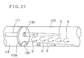
- the radiant tube burner 101 is allowed to operate as mentioned above, whose combustion state will be described using a schema shown in FIG. 27.
- Combustion air A2 having absorbed heat from a heat storage 117 to reach high temperature, passes through the combustion air passage 113 and is injected from the off-center combustion air injection port 133.
- fuel gas F is injected from a small-diameter hole 115c positioned apart from the combustion air injection port 133 and connected to a burner gun 111 and burns in the radiant tube 103 while rolled up in a self-circulating flow G formed by a high-speed jet of combustion air A2.
- fuel gas F is mixed with the self-circulating flow G mainly comprising exhaust gas and becomes a low-calory fuel, so that the flame temperature at the time of combustion is reduced and a low NOx content combustion can be implemented. Furthermore, since combustion reaction takes place on a high-speed air jet, combustion reaction is delayed and the extent of combustion reaction widens, so that combustion reaction energy is dispersed and the flame temperature is further reduced, thereby enabling a low NOx content to be implemented in combustion.
- the maximum temperature point of flame takes place at an intra-furnace position over the thickness of the furnace wall apart and accordingly thermal energy generated by combustion reaction is released into the furnace, so that an excessive rise in flame temperature can be prevented, thereby also enabling a low NOx content to be implemented in combustion.
- the mass flow rate is increased in the combustion reaction field as the self-circulating flow mainly consisting of exhaust gas is rolled up by the high speed air jet, thereby enabling a low NOx content to be implemented in combustion.
- the combustion temperature can be lowered and an amount of generated NOx can be reduced to an extremely small extent.
- COG coke oven gas
- the radiant tube burner 101 was so arranged that the switching of individual burners 105 between the operating state and the waiting state was repeated at an interval of time T, but is not limited to this and may also be so arranged that the temperature of individual heat storages 117 is monitored and operation and wait of individual burners 105 are switched when this temperature reaches a preset temperature.
- a burner 105 is so arranged that individual heat storages 117 are housed side by side on the lower side of the burner body 109, but the housed position of individual heat storages 117 is not limited to this except that it is only required to be situated in the main combustion air passage 113 or at a midway point of the air passage mechanism 110 connected thereto and heat storages 117 may be housed side by side, for example, around the burner gun 111.
- FIGs. 28A-28C show a fifth embodiment of regenerative radiant tube burner according to the present invention.
- FIG. 28A is a structural drawing of this regenerative radiant tube burner, while FIGs. 28B and 28C are sectional views taken along the line I-I and along the line II-II of FIG. 28A, respectively.
- This regenerative radiant tube burner has a structure that burners 202 are oppositely inserted into both ends of a U-shaped radiant tube 201.
- a burner 202 comprises a burner gun 205 incorporating a fuel passage 203 for supplying fuel to the center and a pilot combustion air passage 204 for supplying pilot combustion air to the circumference thereof, a combustion air passage 206 provided around the burner gun 205 and having a larger inside diameter than that thereof, a honeycomb-shaped ceramic made heat storage 207 placed at a halfway point of the combustion air passage 206, a turning vane 208 placed to front of the heat storage 207 similarly in a midway point of the combustion air passage 206 and having an angle of about 45 deg., a baffle 209 for preventing the backflow of fuel gas and a circulating-flow rolled up part 210 enclosed with the burner gun 205, the turning vane 208 and the baffle 209.
- the outside diameter of the combustion air passage 206 is somewhat smaller than the inside diameter of the radiant tube 201 so that a space for turned combustion air to spread outward is preserved.
- combustion exhaust gas is sucked in and passed through a heat storage 207 to accumulate sensitive heat possessed by combustion exhaust gas at the other burner 202.
- combustion air is passed through the accumulated heat storage 207 and preheated, then allowing fuel to burn by using a preheated combustion air.
- the other burner 202 stops the supply of fuel gas and exhausts the combustion exhaust gas having passed through the heat storage 207, so that the supply of combustion air and the exhaust of combustion exhaust gas are switched using the four way valve 211.
- combustion air is supplied to the combustion air passage 206 and is preheated to high temperature by absorbing the heat energy accumulated in the heat storage 207 while passing through the heat storage 207. Then, the combustion air is supplied with turning force from a turning vane 208 and becomes a turning flow 212.
- the flow velocity at the time of combustion air to be injected into the tube is about 50 m/s. Because of having a momentum, the combustion air becomes a flow along the inner wall of the radiant tube 201 under action of a centrifugal force. Because the combustion exhaust gas is sucked from the other burner, the combustion exhaust gas advances toward the other burner 202.
- fuel gas is supplied to the fuel passage 203 and is injected from the tip 203a of the fuel passage 203 into the radiant tube 201 at a flow velocity of about 100 m/s in a straight line but not diffusively.
- a space part based on the difference in diameter. Since the flow velocity of fuel/combustion air is higher than that of the subsequent combustion exhaust gas, this space part becomes relatively a negative pressure as compared with the combustion part.
- a part of combustion exhaust gas generated by combustion of fuel forms a circulating flow 214 toward the fuel passage opposed to the injection direction of fuel.
- the portion 213a of fuel flow 213 situated at the outermost side rides on this circulating current 214 of combustion exhaust gas, is conveyed in the direction of the turning flow 212 of combustion air and rolled up in combustion air, and burns.
- the inner portion 213b relative to the outermost portion 213a of fuel flow 213 advances in front of the outermost portion 213a, but since the circulating flow 214 of combustion exhaust gas advances while circulating, this portion also rides on the circulating flow 214 of combustion exhaust gas with a delay, is conveyed in the direction of the turning flow 212 of combustion air and rolled up in combustion air, and burns.
- the further inner portion 213c of fuel flow 213 also rides on the circulating flow 214 of combustion exhaust gas in a similar manner, is conveyed in the direction of the turning flow 212 of combustion air and rolled up in combustion air, and burns. Thus, combustion proceeds in sequence.
- the fuel injected from the fuel passage does not burn for a short period at one time but gradually burns so that a slow combustion takes place and the combustion temperature does not rise, thereby suppressing the generation of nitrogen oxides (NOx).
- NOx nitrogen oxides
- the nitrogen oxide content amounted to about 130 ppm and a large effect of reduction in NOx was obtained in the method of the present invention using the same conditions as with a conventional air two-stage combustion scheme in which 450 ppm of nitrogen oxides had been generated.
- the regenerative radiant tube burner mentioned above is provided with a circulating-flow inflow part 210 enclosed with the burner gun 205, the turning vane 208 and the baffle 209.
- the reason for provision of such a circulating-flow inflow part 210 is because it was experimentally confirmed that the circulating flow 214 of combustion exhaust gas flows in this circulating-flow inflow part 210 and lowers the temperature of combustion air by heat exchange therewith and at the same time the fuel gas riding on the circulating flow 214 of combustion exhaust gas is rolled up in the turning flow 212 from the starting point of the turning flow 212 of combustion air to burn, thereby suppressing the generation of nitrogen oxides (NOx) more efficiently.
- NOx nitrogen oxides
- the present invention is simplified in structure because of fundamentally comprising one fuel blow inlet and one air blow inlet, and applicable to all diameters of radiant tubes.
- the generated combustion exhaust gas reaches the other end of the radiant tube and passes through the turning vane, so that it passes through a heat storage placed opposite to the burner while turning in a direction of circumference.
- the turning vane operates to make the temperature distribution uniform. Accordingly, since the contained thermal energy is uniformly accumulated from the combustion exhaust gas having reached a heat storage and the temperature of the heat storage becomes more uniform, there is such an effect that higher-temperature preheated air can be obtained.
- honeycomb-shaped ceramic heat storage is employed and the layer of heat storage becomes thinner than that of an aluminum ball-shaped heat storage having the same thermal efficiency, and accordingly there is an advantage that the pressure loss of combustion air is small and combustion can proceed with a low motive force.
- the present invention can give a like arrangement/advantage also in respects of atomized liquid fuel.
- FIG. 30 shows a sixth embodiment of radiant tube burner according to the present invention.
- This embodiment is a trident type radiant tube burner, the radiant tube 310 is provided with tubes 301A-301C and regenerative burners A-C are provided at the end of these tubes, respectively.
- the respective burners A-C comprise heat storages 302a-302c and nozzles 306a-306c penetrating these heat storages, the sectional area of the tubes 301A-301C is overall a nearly equal circle.
- the nozzles 306a-306c are supplied via fuel electromagnetic valves 303a-303c with fuel and the combustion air is supplied via air electromagnetic valves 304a-304c into the tube 301A-301C.
- Combustion exhaust gas is arranged to be exhausted via exhaust gas electromagnetic valves 305a-305c to outside the furnace (tube).
- These electromagnetic valves 303a-303c, 304a-304c and 305a-305c are subjected an ON-OFF control by a control 307 provided with a sequence circuit.
- a pilot burner is provided at the end of each tube (not shown).
- FIG. 31 shows an alternate combustion operation of the embodiment of FIG. 30 and this operation is automatically controlled by the control 307.
- Burner A By igniting a pilot burner, Burner A burns and at that time the tubes 301B and 301C are set to a state that they can suck/exhaust combustion exhaust gas via the heat storages 302b, 302c.
- a combustion and extinguishment method of regenerative burners A-C first, fuel is supplied in a state of being supplied with combustion air to be ignited and extinguishment is made by shutoff of combustion air after a shutoff of fuel supply.
- a lag in the timing of supply between fuel and combustion air is 2 seconds.
- This time lag is one for air purge (air ventilation) of the combustion exhaust gas stuffed into the piping from the air electromagnetic valves 304a-304c to the burner, the heat storages 302a-302c and the like because of sucking in exhaust gas prior to combustion of individual burners.
- this time lag is a time required for replacement of combustion exhaust gas with air.
- Burner A is ignited and set to a combustion state, next Burner A is extinguished to set Burner B to a combustion state and then Burner B is extinguished to set Burner C to a combustion state. While switching a combustion state in sequence like this, the radiant tube burner is set to a predetermined temperature.
- combustion control will be described.
- Burner A combustion of Burner A will be described.
- the air electromagnetic valve 304a is turned to ON to supply combustion air into the tube 301A and at the same time the exhaust gas electromagnetic valves 305b, 305c are turned to ON to exhaust gas.
- the fuel electromagnetic valve 303a is turned to ON and fuel is supplied to start combustion.
- the combustion period of Burner A may be set in accordance with the heat accumulating capacity of heat storages 302a-302c and was set to 30 seconds in this embodiment.
- the fuel electromagnetic valve 303a is turned to OFF and at the time t 1 after the lapse of 2 seconds, the air electromagnetic valve 304a is turned to OFF to transit to combustion of Burner B.
- this stop period prior to the fuel supply was set to 2 seconds on the basis of combustion experiment results, but may be set to more than a time for fuel remaining in the piping from the fuel electromagnetic valve 303a to the burner nozzle to be completely injected due to the residual pressure and the order of at least 0.5 seconds is required.
- Burner B is subjected to an operation similar to that of Burner A. Referring to FIG. 31 (2), combustion of Burner B will be described.
- the air electromagnetic valve 304a is shut off and at the same time the exhaust gas electromagnetic valves 305a is turned to ON, the air electromagnetic valve 304b of Burner B is turned to ON to supply combustion air into the tube 301B.
- the exhaust gas electromagnetic valve 305c keeps an ON state.
- the fuel electromagnetic valve 303b is turned to ON, fuel is supplied and Burner B starts combustion.
- Combustion exhaust gas in the tube 301B is sucked in to the Burner A side and the Burner C side, the sensitive heat of combustion exhaust gas is accumulated in the heat storages 302a, 302c.
- the combustion air supplied from the air electromagnetic valve 304b passes through the heat storage 302b, is preheated with the recovery heat accumulated in the heat storage 302b during a period of t 0 -t 1 and supplied to Burner B.
- Burner C maintains a suction state of combustion exhaust gas
- the heat storage 302c accumulates the sensitive heat of combustion exhaust gas during a period of t 0 -t 2 .
- the fuel electromagnetic valve 303b is shut off and the air electromagnetic valve 304b is shut off at the time t 2 to set Burner B to an extinguished state.
- the exhaust gas electromagnetic valve 305b is tuned to ON and at the same time the air electromagnetic valve 304c is turned ON and exhaust gas electromagnetic valve 305c are turned OFF, respectively, so that a burning state of Burner B transits to a burning state of Burner C.
- the exhaust gas electromagnetic valve 305a keeps an ON state.
- Burner C turns the air electromagnetic valve 304c to ON at the time t 2 , the fuel electromagnetic valve 303c is turned to ON after the lapse of 2 seconds and combustion starts.
- a period of time when the air electromagnetic valve 304c remains ON, or the switching interval of alternate combustion, is 30 seconds and accordingly a period of time when the fuel electromagnetic valve 303c remains ON is 26 seconds.
- the exhaust gas valves 305a, 305b are ON and combustion exhaust gas is exhausted outside the furnace. At that time, the sensitive heat of exhaust gas is accumulated in the heat storages 302a, 302b.
- the combustion air supplied from the air electromagnetic valve 304c is preheated with the heat storage 302c and supplied to Burner C.
- Burner C is set to an extinguished state and Burner A is set to a combustion state.
- combustion is continued till the operation stop or pause of the radiant tube burner while Burner B, Burner C, ... are switched in sequence.
- the exhaust gas electromagnetic valves 305a-305c While the exhaust gas electromagnetic valves 305a-305c are kept ON, sensitive heat of exhaust gas is accumulated in the heat storage of their respective tubes and combustion air in the respective tubes is preheated with the recovered heat of the respective heat storage and is provided to combustion while the air electromagnetic valves 304a-304c are kept ON.
- the alternate combustion period is 30 seconds
- the time lag is 2 seconds
- the pause period prior to the fuel supply is 2 seconds, so that a period of time when the fuel electromagnetic valves 303a-303c are kept ON is 26 seconds.
- the thermal efficiency of a radiant tube burner is improved.
- combustion is continued while combustion tubes are switched in sequence.
- the radiant tube burner of the present invention is an alternate combustion equipment in which ignition/extinguishment are repeated at a short interval, a flame monitor is installed and safety measures are taken.
- a CO detector is installed in the exhaust gas flue to monitor incomplete combustion.
- FIG. 32 a seventh embodiment of the present invention will be described.
- the embodiment of FIG. 32 differs in the shape of radiant tubes from that of FIG. 30, but is otherwise identical and like symbols are given to like parts similar to those of FIG. 30.
- the radiant tube 310 comprises a trunk tube 310A and branch tubes 301A-301C extending from the trunk tube. At the end of the branch tubes 301A-301C, regenerative Burners A - C are provided.
- the fuel supply electromagnetic valves 303a-303c, the air electromagnetic valves 304a-304c for controlling combustion air and the exhaust gas electromagnetic valves 305a-305c are the same as those of the embodiment of FIG. 30, and the ON-OFF control thereof is carried out with a control device 307.
- the trunk tube 310A serves as an equalizer (header) for combustion exhaust gas flowing therethrough.
- Burners A-B burn alternately and, for example, even if combustion exhaust gas passes through the trunk tube 310A and passes respectively through trunk tubes 301A, 301C, the respective flow rates of branch tubes 301A, 301C become nearly equal.
- the relation is set as (sectional area in a trunk tube)/(sectional area in a branch tube) ⁇ 1.5 .
- Burners A-C perform alternate combustion operation as described in FIG. 31 and accordingly the description thereof will be omitted.
- FIG. 33 comprises four regenerative burners and the number of electromagnetic valves also increases corresponding to this number, but the fundamental arrangement is the same as with the embodiment of FIG. 32 and like symbols are given to parts similar to those of FIG. 32.
- the radiant tube 310 comprises a trunk tube 310A and branch tubes 301A-301D provided on the trunk tube 310A.
- H regenerative Burners A - D are provided at the end of the branch tubes 301A-301D.
- Burners A - D comprise heat storages 302a-302d and nozzles 306a-306d, respectively.
- fuel electromagnetic valves 303a-303d, air electromagnetic valves 304a-304d for controlling combustion air and exhaust gas electromagnetic valves 305a-305d are provided. These electromagnetic valves are controlled with a control device 307.
- the relation of sectional area between the trunk 310A and the branch tubes 301A-301D is set as (sectional area in a trunk tube)/(sectional area in a branch tube) ⁇ 2 .
- FIGs. 34 and 35 Combustion operation of this embodiment will be described referring to FIGs. 34 and 35.
- control of combustion is carried out by switching the burning burners A - D in the sequence of Burners A, B, C and D as shown in FIG. 34.
- combustion control of this embodiment for example, when one Burner A burns, combustion exhaust gas is so controlled as to be sucked to the other three Burners B - D sides.
- FIG. 35 shows a detailed timing chart thereof.
- (1) - (4) show combustion/exhaust operations of Burners A-D.
- Burner A First, operations of Burner A will be described referring to FIG. 35 (1).
- the air electromagnetic valve 304a is turned to ON.
- the fuel electromagnetic valve 303a is turned to ON to set Burner A to a burning state.
- Burners B, C and D turn the exhaust gas electromagnetic valves 305b - 305d to ON at the time t 0 to exhaust combustion exhaust gas to outside the furnace.
- the air electromagnetic valve 304a is turned to OFF at the time t 1 to set Burner A to an extinguished state
- the exhaust gas electromagnetic valve 305a is turned to ON and the exhaust gas electromagnetic valves 305c and 305d for Burners C and D keep an ON state.
- the air electromagnetic valve 304b is turned to ON, the fuel electromagnetic valve 303b is turned to ON to set Burner B to a burning state and at the same time the exhaust gas electromagnetic valve 305b to OFF.
- the air electromagnetic valve 304b is turned to OFF at the time t 2 to extinguish Burner B.
- the exhaust gas electromagnetic valve 305b is turned to ON, so that a burning state of Burner B transits to a burning state of Burner C.
- Burner C The combustion operation of Burner C will be described.
- the air electromagnetic valve 304c is turned to ON, the fuel electromagnetic valve 303c is turned to ON to set Burner C to a burning state and at the same time the exhaust gas electromagnetic valve 305c to OFF.
- the air electromagnetic valve 304c is turned to OFF at the time t 3 to extinguish Burner C.
- the exhaust gas electromagnetic valve 305c is turned to ON.
- Burner D operations of Burner D will be described.
- the air electromagnetic valve 304d is turned to ON, the fuel electromagnetic valve 303d is turned to ON to set Burner D to a burning state and at the same time the exhaust gas electromagnetic valve 305d to OFF.
- the air electromagnetic valve 304d is turned to OFF at the time t 4 to extinguish Burner D.
- the exhaust gas electromagnetic valve 305d is turned to ON.
- control of combustion may be also carried out in the sequence of Burners A, B, C and D.
- FIG. 37 comprises the respective regenerative burners provided corresponding to five branching tubes. Like symbols are given to parts similar to those of FIG. 33.
- the radiant tube 310 has branch tubes 301A - 301E provided for a trunk tube 310A and regenerative burners A - E provided at the end thereof.
- Burners A - E comprise heat storages 302a - 302e and nozzles 306a - 306e, respectively.
- fuel electromagnetic valves 303a-303e, air electromagnetic valves 304a - 304e for controlling combustion air and exhaust gas electromagnetic valves 305a - 305e are provided. These electromagnetic valves are controlled with a control device 307.
- FIG. 38 shows an example that two burners are allowed to burn and three burners are operated to suck in combustion exhaust gas.
- the ON-OFF operation of these electromagnetic valves is the same as that described above. Needless to say, it is evident that the operating pattern is not limited to that of FIG. 38 but may be another pattern.
- radiant tube burners according to the present invention were described by enumerating various embodiments, but any number of branch tubes may be provided for the trunk tube. And, a combination of burning burners and not burning burners is optional.
- radiant tubes with a circular sectional shape were employed; however, such a pipe-shaped arrangement is not required but a polygonal-section arrangement is also allowable.
- a fin-equipped arrangement for an increase in heat transmission area is also allowable.
- metal e.g., heat-resisting steel pipe
- a radiant tube may be made up of ceramics.
- any material is available if capable of maintaining a sufficient durability and is not required to be limited to these.
- FIG. 39 is a structural drawing showing the fundamental concept for verifying a combustion method of a radiant tube burner according to the present invention.
- Numeral 401 denotes a radiant tube burner, which is equal to a conventional in that gaseous fuel of hydrocarbon type is normally employed, the burner is heated by passing of combustion gas through the interior and heat is radiated from the outer surface to heat a heating furnace, heat-treating furnace or the like.
- Numeral 402 denotes a radiant tube for closing both ends and partitioning a space to form a combustion chamber.
- Numeral 403 denotes fuel injection ports provided at both ends of said radiant tube 402 and connected to a hydrocarbon type gaseous fuel piping.
- Numeral 404 denotes combustion air injection ports provided at both ends of said radiant tube 402, connected to a not shown air supply installation and exhaust installation and jointly used for air supply and for gas exhaust, where the other functions as a discharge port when the port of either one side functions as a charge port.
- Numeral 405 denotes a heat accumulating material stuffed in combustion air injection ports 404 and composed of globular ceramic, porous ceramic or other molded ceramic, which is deprived of heat by supply air when the combustion air injection port 404 functions as a supply port and is heated by exhaust gas when the combustion air injection port functions as a discharge port. As shown in FIG.
- a fuel injection port 403 has a slit shape for executing a high-speed mix of fuel with air and a combustion air injection port 404 has a circular shape for enlarging the self-circulating flow, both of which are positioned to be apart from each other.
- the fuel injection port 403 and the combustion air injection port 404 are both set off-center, but only either one may be set off-center.
- combustion of a radiant tube is alternately executed at both ends. That is, while one combustion air injection port 404 is burning, the other combustion air injection port 404 is made to function as a discharge port of combustion gas and heat is allowed to be accumulated in a stuffed heat-accumulating material. After a sufficient accumulation of heat, combustion is stopped once, the combustion air injection port 404 having functioned as a discharge port is made to function as an air charge port and preheating of air is carried out with heat accumulated in the heat-accumulating material.
- the charge speed of combustion air supplied from the combustion air injection port 404 is made substantially larger than that employed in a conventional radiant tube burner, vortex flow is generated near the extension direction of the fuel injection port 403 and a self-circulating flow is derived in combustion gas to dilute a high-temperature combustion gas and lower the combustion temperature, and moreover the generation time of nitrogen oxides determined from the length of a radiant tube and the flow velocity of combustion gas is shortened to keep the reaction in a non-equilibrium state, thereby decreasing the nitrogen oxide content in exhaust gas.
- Preventing the combustion reaction from proceeding to an equilibrium state can be attained by shortening the stay time of the high-temperature part with the velocity of gas flow retained.
- the locally generated portion with an air ratio of 1.0 is greatly decreased and the combustion time in a radiant tube is made shorter than a period for a perfect completion of combustion reaction, so that the combustion in a radiant tube can be kept non-equilibrium.
- the radiant tube (402) is a straight tube.
- Table 4 shows the results obtained by a 20-second-interval intermittent combustion as shown in FIG. 41 with a mean combustion gas rate of 50 m/s at the radiant tube outlet in a radiant tube (402), 2 m in length and 100 mm in tube diameter. It is evident from these results that the present invention can achieve a lower nitrogen oxide content and a higher combustion efficiency than those of a conventional combustion method.
- Table 4 Maximum temperature (°C) Nox generated quantity (ppm) Conventional example 1800 700 Present invention 1750 100
Landscapes
- Engineering & Computer Science (AREA)
- Chemical & Material Sciences (AREA)
- Combustion & Propulsion (AREA)
- Mechanical Engineering (AREA)
- General Engineering & Computer Science (AREA)
- Combustion Of Fluid Fuel (AREA)
- Gas Burners (AREA)
Applications Claiming Priority (16)
| Application Number | Priority Date | Filing Date | Title |
|---|---|---|---|
| JP25457094A JP3691863B2 (ja) | 1994-09-24 | 1994-09-24 | ラジアントチューブバーナ及びそれを用いた交互燃焼型ラジアントチューブバーナシステム |
| JP254570/94 | 1994-09-24 | ||
| JP25457094 | 1994-09-24 | ||
| JP7052225A JPH08247421A (ja) | 1995-03-13 | 1995-03-13 | ラジアントチューブバーナ |
| JP07052224A JP3111848B2 (ja) | 1995-03-13 | 1995-03-13 | ラジアントチューブバーナの燃焼方法 |
| JP52225/95 | 1995-03-13 | ||
| JP5222595 | 1995-03-13 | ||
| JP5222495 | 1995-03-13 | ||
| JP52224/95 | 1995-03-13 | ||
| JP21448595 | 1995-08-23 | ||
| JP214485/95 | 1995-08-23 | ||
| JP21448595A JP3189640B2 (ja) | 1995-08-23 | 1995-08-23 | 蓄熱式ラジアントチューブバーナ |
| JP22353195A JP3332306B2 (ja) | 1995-08-31 | 1995-08-31 | ラジアントチューブ式加熱装置 |
| JP223531/95 | 1995-08-31 | ||
| JP22353195 | 1995-08-31 | ||
| PCT/JP1995/001916 WO1996009496A1 (fr) | 1994-09-24 | 1995-09-22 | Bruleur a tube rayonnant et procede de fonctionnement de tels bruleurs a tube rayonnant |
Publications (3)
| Publication Number | Publication Date |
|---|---|
| EP0736732A1 true EP0736732A1 (fr) | 1996-10-09 |
| EP0736732A4 EP0736732A4 (fr) | 1998-01-28 |
| EP0736732B1 EP0736732B1 (fr) | 2001-12-19 |
Family
ID=27522992
Family Applications (1)
| Application Number | Title | Priority Date | Filing Date |
|---|---|---|---|
| EP95932212A Expired - Lifetime EP0736732B1 (fr) | 1994-09-24 | 1995-09-22 | Bruleur a tube rayonnant |
Country Status (6)
| Country | Link |
|---|---|
| US (1) | US6027333A (fr) |
| EP (1) | EP0736732B1 (fr) |
| KR (1) | KR100245443B1 (fr) |
| CA (1) | CA2176488C (fr) |
| DE (1) | DE69524726T2 (fr) |
| WO (1) | WO1996009496A1 (fr) |
Cited By (7)
| Publication number | Priority date | Publication date | Assignee | Title |
|---|---|---|---|---|
| EP0809072A3 (fr) * | 1996-05-22 | 1999-03-24 | Toyota Jidosha Kabushiki Kaisha | Dispositif d'alimentation en carburant et air pour le pilote |
| EP1018619A4 (fr) * | 1997-09-26 | 2001-06-06 | Nippon Furnace Kogyo Kk | Systeme de bruleur regeneratif a accumulation de chaleur et a interversion |
| EP1101064A4 (fr) * | 1998-07-30 | 2001-11-07 | Bloom Eng Co Inc | Bruleur pour combustion asymetrique et procede correspondant |
| EP0878681A3 (fr) * | 1997-04-25 | 2002-09-25 | Nippon Furnace Kogyo Kaisha Ltd. | Appareil et méthode pour le contrôle de la cuisson |
| EP1422473A1 (fr) * | 2002-11-21 | 2004-05-26 | Hauck Manufacturing Company | Ensamble brûleur à tube en "U" à flamme de diffusion ayant une stabilisation unique de la flamme |
| US7175423B1 (en) | 2000-10-26 | 2007-02-13 | Bloom Engineering Company, Inc. | Air staged low-NOx burner |
| CN103290201A (zh) * | 2012-02-24 | 2013-09-11 | 北京京杰锐思技术开发有限公司 | 一种无氧化加热炉 |
Families Citing this family (29)
| Publication number | Priority date | Publication date | Assignee | Title |
|---|---|---|---|---|
| US6793486B2 (en) * | 1998-07-30 | 2004-09-21 | Bloom Engineering Company, Inc. | Burner for non-symmetrical combustion and method |
| US6178964B1 (en) * | 1999-09-29 | 2001-01-30 | Gas Research Institute | Fluid heating apparatus |
| RU2191951C1 (ru) * | 2001-05-08 | 2002-10-27 | Открытое акционерное общество "Череповецкий сталепрокатный завод" | U-образный газовый нагреватель и способ его сборки |
| KR20030018188A (ko) * | 2001-08-27 | 2003-03-06 | 주식회사 포스코 | 이중 연료노즐을 구비한 저질소산화물 축열식 복사관 버너 |
| RU2227248C2 (ru) * | 2001-11-19 | 2004-04-20 | Открытое акционерное общество "Промгаз" | Рециркуляционная u-образная радиационная труба |
| RU2260746C2 (ru) * | 2002-12-31 | 2005-09-20 | Открытое акционерное общество "Промгаз" | Радиационная труба |
| WO2004076920A1 (fr) * | 2003-02-25 | 2004-09-10 | Nippon Furnace Kogyo Kaisha Ltd. | Appareil de bruleur a tube radiant de regeneration de type a combustion alternatif |
| US6971871B2 (en) * | 2004-02-06 | 2005-12-06 | Solaronics, Inc. | Variable low intensity infrared heater |
| US7104787B2 (en) * | 2004-05-06 | 2006-09-12 | Eclipse, Inc. | Apparatus for radiant tube exhaust gas entrainment |
| RU2295671C2 (ru) * | 2005-04-08 | 2007-03-20 | Открытое акционерное общество "Промгаз" (ОАО "Промгаз") | Способ сокращения эмиссии окислов азота |
| PL1798470T3 (pl) * | 2005-12-13 | 2008-08-29 | Schwank Gmbh | Urządzenie grzewcze i sposób jego pracy |
| AU2007310971A1 (en) * | 2006-10-18 | 2008-04-24 | Lean Flame, Inc. | Premixer for gas and fuel for use in combination with energy release/conversion device |
| US8105076B2 (en) * | 2007-08-06 | 2012-01-31 | Thomas & Betts International, Inc. | High efficiency radiant heater |
| WO2009039399A1 (fr) * | 2007-09-21 | 2009-03-26 | Wessex Incorporated | Tube rayonnant |
| AU2008324755B2 (en) * | 2007-11-05 | 2012-05-03 | Actinon Pte. Ltd. | Kiln |
| DE102007057410B3 (de) * | 2007-11-27 | 2009-07-30 | Uhde Gmbh | Mechanismus und Verfahren zur automatisierbaren Verriegelung von Türen, Türkörpern oder Türrahmen horizontaler Koksofenkammern |
| DE202008009065U1 (de) * | 2008-07-04 | 2008-10-09 | WS Wärmeprozesstechnik GmbH | Strahlungsheizanordnung mit Verzugkompensation |
| US9587823B2 (en) * | 2009-03-25 | 2017-03-07 | Wallace Horn | Laminar flow jets |
| DE212009000229U1 (de) * | 2009-08-18 | 2012-04-12 | Fbb Engineering Gmbh | Strahlungsbrenner sowie Strahlungsbrenneranordnung |
| US8689562B2 (en) | 2009-09-13 | 2014-04-08 | Donald W. Kendrick | Combustion cavity layouts for fuel staging in trapped vortex combustors |
| DE102009058304B4 (de) * | 2009-12-15 | 2013-01-17 | Maerz Ofenbau Ag | Gleichstrom-Gegenstrom-Regenerativ-Kalkofen sowie Verfahren zum Betreiben desselben |
| FR2977004A1 (fr) * | 2011-06-27 | 2012-12-28 | Cmi Thermline Services | Dispositif et procede de gestion d'imbrules pour bruleurs regeneratifs, bruleur comportant un tel dispositif |
| US9546793B2 (en) | 2013-07-10 | 2017-01-17 | Finn Green Technology LLC | Radiant heater and combustion chamber |
| US10458646B2 (en) | 2014-09-25 | 2019-10-29 | Selas Heat Technology Company Llc | Low NOx, high efficiency, high temperature, staged recirculating burner and radiant tube combustion system |
| CA2964521C (fr) * | 2016-04-27 | 2025-12-23 | Superior Radiant Products Ltd. | Optimisation de dispositifs de chauffage de tube radiant au gaz |
| CZ307407B6 (cs) * | 2017-03-13 | 2018-08-01 | Htt Engineering, Spol. S R.O. | Kombinovaný hořák pro dmychání oxidačního plynu a paliva do tavicí pece |
| CN108397770A (zh) * | 2018-02-27 | 2018-08-14 | 赵升智 | 中低热值燃气蓄热式辐射管燃气燃烧器 |
| WO2020183117A1 (fr) * | 2019-03-11 | 2020-09-17 | Thermal Recycling (Uk) Ltd | Commande de four |
| BE1027839B1 (fr) * | 2019-12-10 | 2021-07-08 | Drever International Sa | Élément de chauffage radiant à extrémité libre |
Family Cites Families (15)
| Publication number | Priority date | Publication date | Assignee | Title |
|---|---|---|---|---|
| US2398611A (en) * | 1946-04-16 | Igniting means for burners | ||
| US2250680A (en) * | 1939-07-11 | 1941-07-29 | Lee Wilson Sales Corp | Combustion tube burner |
| US2712308A (en) * | 1950-11-22 | 1955-07-05 | Richard T Keating | Deep fryer |
| US4162890A (en) * | 1977-05-02 | 1979-07-31 | Bloom Engineering Company, Inc. | Combustion apparatus |
| JPS62242711A (ja) * | 1985-11-29 | 1987-10-23 | Nippon Nenshiyou Syst Kk | ラジアントチユ−ブバ−ナ |
| JPS62134410A (ja) * | 1985-12-06 | 1987-06-17 | Nippon Nenshiyou Syst Kk | ラジアントチユ−ブバ−ナ |
| JPH0223950Y2 (fr) * | 1985-12-23 | 1990-06-29 | ||
| JPS63116011A (ja) * | 1986-11-05 | 1988-05-20 | Nippon Nenshiyou Syst Kk | ラジアントチユ−ブバ−ナ |
| US4926842A (en) * | 1987-05-11 | 1990-05-22 | North American Mfg. Co. | Immersion tube heater treater improved immersion tube heater treater |
| GB8720468D0 (en) * | 1987-08-29 | 1987-10-07 | Boc Group Plc | Flame treatment method |
| JPH0223950A (ja) * | 1988-07-13 | 1990-01-26 | Tokyo Keiki Co Ltd | 超音波診断装置 |
| JPH0311202A (ja) * | 1989-06-08 | 1991-01-18 | Tokyo Gas Co Ltd | ラジアントチューブの窒素酸化物低減燃焼方法 |
| JPH0665705A (ja) * | 1992-08-24 | 1994-03-08 | Dai Ichi High Frequency Co Ltd | 耐摩耗性・耐食性のある皮膜の形成方法 |
| JP2579773Y2 (ja) * | 1993-02-25 | 1998-08-27 | 中外炉工業株式会社 | 蓄熱式ラジアントチューブシステム |
| GB2280257B (en) * | 1993-07-20 | 1996-09-25 | Ambi Rad Ltd | Space heating appliances |
-
1995
- 1995-09-22 EP EP95932212A patent/EP0736732B1/fr not_active Expired - Lifetime
- 1995-09-22 US US08/648,155 patent/US6027333A/en not_active Expired - Fee Related
- 1995-09-22 CA CA002176488A patent/CA2176488C/fr not_active Expired - Fee Related
- 1995-09-22 WO PCT/JP1995/001916 patent/WO1996009496A1/fr not_active Ceased
- 1995-09-22 KR KR1019960702754A patent/KR100245443B1/ko not_active Expired - Fee Related
- 1995-09-22 DE DE69524726T patent/DE69524726T2/de not_active Expired - Fee Related
Cited By (11)
| Publication number | Priority date | Publication date | Assignee | Title |
|---|---|---|---|---|
| EP0809072A3 (fr) * | 1996-05-22 | 1999-03-24 | Toyota Jidosha Kabushiki Kaisha | Dispositif d'alimentation en carburant et air pour le pilote |
| US6079976A (en) * | 1996-05-22 | 2000-06-27 | Toyota Jidosha Kabushiki Kaisha | Structure for supply of fuel and pilot air |
| EP0878681A3 (fr) * | 1997-04-25 | 2002-09-25 | Nippon Furnace Kogyo Kaisha Ltd. | Appareil et méthode pour le contrôle de la cuisson |
| EP1018619A4 (fr) * | 1997-09-26 | 2001-06-06 | Nippon Furnace Kogyo Kk | Systeme de bruleur regeneratif a accumulation de chaleur et a interversion |
| EP1101064A4 (fr) * | 1998-07-30 | 2001-11-07 | Bloom Eng Co Inc | Bruleur pour combustion asymetrique et procede correspondant |
| CZ298443B6 (cs) * | 1998-07-30 | 2007-10-03 | Bloom Engineering Company, Inc. | Horák pro nesymetrické spalování |
| US7175423B1 (en) | 2000-10-26 | 2007-02-13 | Bloom Engineering Company, Inc. | Air staged low-NOx burner |
| US6872070B2 (en) | 2001-05-10 | 2005-03-29 | Hauck Manufacturing Company | U-tube diffusion flame burner assembly having unique flame stabilization |
| EP1422473A1 (fr) * | 2002-11-21 | 2004-05-26 | Hauck Manufacturing Company | Ensamble brûleur à tube en "U" à flamme de diffusion ayant une stabilisation unique de la flamme |
| CN103290201A (zh) * | 2012-02-24 | 2013-09-11 | 北京京杰锐思技术开发有限公司 | 一种无氧化加热炉 |
| CN103290201B (zh) * | 2012-02-24 | 2015-07-22 | 北京京杰锐思技术开发有限公司 | 一种无氧化加热炉 |
Also Published As
| Publication number | Publication date |
|---|---|
| DE69524726D1 (de) | 2002-01-31 |
| KR100245443B1 (ko) | 2000-03-02 |
| US6027333A (en) | 2000-02-22 |
| CA2176488A1 (fr) | 1996-03-28 |
| EP0736732A4 (fr) | 1998-01-28 |
| WO1996009496A1 (fr) | 1996-03-28 |
| KR960706049A (ko) | 1996-11-08 |
| EP0736732B1 (fr) | 2001-12-19 |
| CA2176488C (fr) | 2000-06-20 |
| DE69524726T2 (de) | 2002-08-14 |
Similar Documents
| Publication | Publication Date | Title |
|---|---|---|
| EP0736732B1 (fr) | Bruleur a tube rayonnant | |
| JP3460441B2 (ja) | 燃焼装置および該燃焼装置を具備した熱設備 | |
| CN1109845C (zh) | 低氧化氮燃烧器 | |
| RU2477325C2 (ru) | Способ и установка для нагрева металлической полосы, в частности, с целью отжига | |
| CN115574595B (zh) | 氨燃烧还原低NOx排放连续加热炉窑及控制方法 | |
| JPH064171Y2 (ja) | ラジアントチユ−ブ | |
| CN104696965A (zh) | 一种直流式弥散燃烧的管式加热炉系统及燃烧器 | |
| JP4106553B2 (ja) | マイクロコンバスタ | |
| KR100583819B1 (ko) | 자기 축열식 단일 라디안트 튜브 버너 | |
| JP3149666B2 (ja) | 放射加熱装置およびその燃焼方法 | |
| JP3823403B2 (ja) | ラジアントチューブバーナシステム及びその運転方法 | |
| JP2571556Y2 (ja) | 蓄熱再生式バーナ | |
| JPH08247421A (ja) | ラジアントチューブバーナ | |
| JPH09229354A (ja) | 加熱炉、その燃焼制御方法及び燃焼制御装置 | |
| JP3893677B2 (ja) | 蓄熱式バーナを有する炉 | |
| JPH01222102A (ja) | 熱回収式燃焼装置 | |
| JP3332306B2 (ja) | ラジアントチューブ式加熱装置 | |
| JP3044286B2 (ja) | 連続焼鈍炉 | |
| JPH09243056A (ja) | 蓄熱切替式バーナ | |
| CN207849371U (zh) | 工业炉用脱硝蓄热式烧嘴 | |
| CN111425856A (zh) | 一种蓄热式辐射管烧嘴 | |
| JP2673640B2 (ja) | 給湯機の燃焼制御方法 | |
| KR100631109B1 (ko) | 자기축열식 단일튜브 버너의 연소공기 분할공급장치 | |
| JP3289437B2 (ja) | 蓄熱式バーナを用いた加熱炉の燃焼方法 | |
| CN219140824U (zh) | 蓄热式助燃结构和燃烧炉 |
Legal Events
| Date | Code | Title | Description |
|---|---|---|---|
| PUAI | Public reference made under article 153(3) epc to a published international application that has entered the european phase |
Free format text: ORIGINAL CODE: 0009012 |
|
| 17P | Request for examination filed |
Effective date: 19960621 |
|
| AK | Designated contracting states |
Kind code of ref document: A1 Designated state(s): DE FR GB IT NL |
|
| A4 | Supplementary search report drawn up and despatched | ||
| AK | Designated contracting states |
Kind code of ref document: A4 Designated state(s): DE FR GB IT NL |
|
| 17Q | First examination report despatched |
Effective date: 20000310 |
|
| GRAG | Despatch of communication of intention to grant |
Free format text: ORIGINAL CODE: EPIDOS AGRA |
|
| RTI1 | Title (correction) |
Free format text: RADIANT TUBE BURNER |
|
| RTI1 | Title (correction) |
Free format text: RADIANT TUBE BURNER |
|
| RTI1 | Title (correction) |
Free format text: RADIANT TUBE BURNER |
|
| GRAG | Despatch of communication of intention to grant |
Free format text: ORIGINAL CODE: EPIDOS AGRA |
|
| GRAH | Despatch of communication of intention to grant a patent |
Free format text: ORIGINAL CODE: EPIDOS IGRA |
|
| GRAH | Despatch of communication of intention to grant a patent |
Free format text: ORIGINAL CODE: EPIDOS IGRA |
|
| GRAA | (expected) grant |
Free format text: ORIGINAL CODE: 0009210 |
|
| AK | Designated contracting states |
Kind code of ref document: B1 Designated state(s): DE FR GB IT NL |
|
| PG25 | Lapsed in a contracting state [announced via postgrant information from national office to epo] |
Ref country code: NL Free format text: LAPSE BECAUSE OF FAILURE TO SUBMIT A TRANSLATION OF THE DESCRIPTION OR TO PAY THE FEE WITHIN THE PRESCRIBED TIME-LIMIT Effective date: 20011219 Ref country code: FR Free format text: LAPSE BECAUSE OF FAILURE TO SUBMIT A TRANSLATION OF THE DESCRIPTION OR TO PAY THE FEE WITHIN THE PRESCRIBED TIME-LIMIT Effective date: 20011219 |
|
| REG | Reference to a national code |
Ref country code: GB Ref legal event code: IF02 |
|
| REF | Corresponds to: |
Ref document number: 69524726 Country of ref document: DE Date of ref document: 20020131 |
|
| NLV1 | Nl: lapsed or annulled due to failure to fulfill the requirements of art. 29p and 29m of the patents act | ||
| EN | Fr: translation not filed | ||
| PLBE | No opposition filed within time limit |
Free format text: ORIGINAL CODE: 0009261 |
|
| STAA | Information on the status of an ep patent application or granted ep patent |
Free format text: STATUS: NO OPPOSITION FILED WITHIN TIME LIMIT |
|
| 26N | No opposition filed | ||
| NLV1 | Nl: lapsed or annulled due to failure to fulfill the requirements of art. 29p and 29m of the patents act | ||
| PGFP | Annual fee paid to national office [announced via postgrant information from national office to epo] |
Ref country code: GB Payment date: 20030917 Year of fee payment: 9 |
|
| PGFP | Annual fee paid to national office [announced via postgrant information from national office to epo] |
Ref country code: DE Payment date: 20031002 Year of fee payment: 9 |
|
| PG25 | Lapsed in a contracting state [announced via postgrant information from national office to epo] |
Ref country code: GB Free format text: LAPSE BECAUSE OF NON-PAYMENT OF DUE FEES Effective date: 20040922 |
|
| PG25 | Lapsed in a contracting state [announced via postgrant information from national office to epo] |
Ref country code: DE Free format text: LAPSE BECAUSE OF NON-PAYMENT OF DUE FEES Effective date: 20050401 |
|
| GBPC | Gb: european patent ceased through non-payment of renewal fee |
Effective date: 20040922 |
|
| PG25 | Lapsed in a contracting state [announced via postgrant information from national office to epo] |
Ref country code: IT Free format text: LAPSE BECAUSE OF NON-PAYMENT OF DUE FEES Effective date: 20050922 |