EP0736740B1 - Positionnement de munitions - Google Patents
Positionnement de munitions Download PDFInfo
- Publication number
- EP0736740B1 EP0736740B1 EP19950118614 EP95118614A EP0736740B1 EP 0736740 B1 EP0736740 B1 EP 0736740B1 EP 19950118614 EP19950118614 EP 19950118614 EP 95118614 A EP95118614 A EP 95118614A EP 0736740 B1 EP0736740 B1 EP 0736740B1
- Authority
- EP
- European Patent Office
- Prior art keywords
- case
- cartridge
- ammunition
- guide surface
- holding groove
- Prior art date
- Legal status (The legal status is an assumption and is not a legal conclusion. Google has not performed a legal analysis and makes no representation as to the accuracy of the status listed.)
- Expired - Lifetime
Links
- 238000010304 firing Methods 0.000 claims description 24
- 239000000314 lubricant Substances 0.000 claims description 3
- 238000005474 detonation Methods 0.000 claims 13
- 238000009527 percussion Methods 0.000 claims 2
- 230000003014 reinforcing effect Effects 0.000 claims 2
- 238000004880 explosion Methods 0.000 description 3
- 238000004519 manufacturing process Methods 0.000 description 3
- 230000003071 parasitic effect Effects 0.000 description 3
- 239000011324 bead Substances 0.000 description 2
- 230000015572 biosynthetic process Effects 0.000 description 2
- 230000005489 elastic deformation Effects 0.000 description 2
- 241001295925 Gegenes Species 0.000 description 1
- 230000000903 blocking effect Effects 0.000 description 1
- 238000004140 cleaning Methods 0.000 description 1
- 230000007547 defect Effects 0.000 description 1
- 238000005553 drilling Methods 0.000 description 1
- 239000000428 dust Substances 0.000 description 1
- 230000007613 environmental effect Effects 0.000 description 1
- 239000002360 explosive Substances 0.000 description 1
- 239000012535 impurity Substances 0.000 description 1
- 230000001788 irregular Effects 0.000 description 1
- 239000000463 material Substances 0.000 description 1
- 239000002184 metal Substances 0.000 description 1
- 230000002787 reinforcement Effects 0.000 description 1
- 238000003860 storage Methods 0.000 description 1
- XLYOFNOQVPJJNP-UHFFFAOYSA-N water Substances O XLYOFNOQVPJJNP-UHFFFAOYSA-N 0.000 description 1
Images
Classifications
-
- F—MECHANICAL ENGINEERING; LIGHTING; HEATING; WEAPONS; BLASTING
- F41—WEAPONS
- F41A—FUNCTIONAL FEATURES OR DETAILS COMMON TO BOTH SMALLARMS AND ORDNANCE, e.g. CANNONS; MOUNTINGS FOR SMALLARMS OR ORDNANCE
- F41A9/00—Feeding or loading of ammunition; Magazines; Guiding means for the extracting of cartridges
- F41A9/54—Cartridge guides, stops or positioners, e.g. for cartridge extraction
- F41A9/55—Fixed or movable guiding means, mounted on, or near, the cartridge chamber
Definitions
- the invention relates to a device for supporting the supply of an ammunition cartridge to a firing point of a firearm and to lead away the cartridge case of the Ammunition cartridge from the ignition point according to the preamble of claim 1 such a device is well known.
- Specially designed are designed to feed ammunition cartridges into firearms Feeders used.
- Such feeders are for example rotatable drums with multiple openings for ammunition cartridges.
- the ammunition cartridges are from outside of the firearm body arranged magazines pushed in drums and conveyed to the firing position by rotating the drums. To the The ammunition rounds are fired using firing pins.
- the empty cartridge cases are blown up by the explosion pressure and over Guide devices, for example via ejection channels, from the ignition points led away.
- a first disadvantage of such feeders is that Explosive pressure elastic deformations of the firearm body and plastic deformations of the cartridge cases are generated. When easing of the explosion pressure, let the elastic deformation of the firearm body after, during the plastic deformations of the cartridge cases persist. When using a firearm with a drum feed this leads to parasitic frictional force moments between the deformed Cartridge cases and the firearm body. The speed of rotation the drum is slowed down, the bombardment rate is reduced, which is undesirable. Again, the higher the drum speed are, the more powerful the firearm is, the bigger are the frictional force moments that occur.
- Frictional force moments due to plastic deformation of the cartridge cases should be reduced or eliminated.
- the appearance of chips that occur in the Ignition of the ammunition cartridges occurs, and that in the area of the firing pin holes come and so by clogging these holes Avoid functioning of firearms should be avoided become.
- This task is to be carried out using known and proven means and manufacturing processes be solvable.
- the device is said to use standardized ammunition cartridges be operable. It should be of a simple, robust design. 0 Finally, it should be reliable, largely maintenance-free and have a long service life his.
- a device for feeding ammunition is known from DE-C-719 360 , which has a first guide surface, a second guide surface, an ignition point and a holding groove.
- this is a device for the two-sided supply of ammunition cartridges with a reciprocating movement, and not a device for supporting the supply of an ammunition cartridge to an ignition point and guiding the cartridge case of the ammunition cartridge away from the ignition point.
- the idea of the invention is to supply ammunition cartridges to support ignition points by a positioning device.
- Ammunition cartridges are via a first guide surface and by means of a holding groove sliding and holding guided and checked at the ignition point and precisely positioned.
- the geometry of the positioning device is in line with the geometry adapted from standard ammunition cartridges.
- Ammunition cartridges slide with their sleeve bottoms over an advantageously oblique to the weft direction arranged guide surface and are with their sleeve edges in the holding groove kept leading.
- the ignition screw groove is a recess for deformed ignition screws of the ammunition cartridges and Cartridge cases and allows the case bottoms to slide smoothly deformed ignition screws on the other guide surface.
- FIG. 1 is a top view
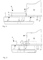
- Figure 2 is a front view
- Figure 3 is a side view.
- This Design of the positioning device P is advantageous but not mandatory.
- the person skilled in the art is aware of the present invention in this regard diverse possibilities of varying this embodiment Available.
- Such a positioning device P is particularly suitable for Use in automatic firearms as used in the Swiss Patent applications P0663CH and P0664CH are disclosed.
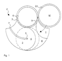
- FIG. 1 is a top view against the weft direction.
- the feed and The path of the ammunition cartridges is clockwise.
- the viewer looks into the opening 5 for the firing pin to fire the ammunition rounds M.
- FIG. 1 there are two guide surfaces 1, 2, one positioning surface 8 and a retaining groove 3 of the positioning device P merging into one another, worked in one piece in a base plate.
- the ammunition cartridges M are advantageously in the cartridge chambers kept stored by drums, fed by rotating the drums.
- Other feeding devices such as the use of a Feed levers are possible.
- Such feeding devices can be designed freely and not shown in the figures for reasons of clarity.
- Those skilled in the art are familiar with the present invention in a variety of ways Possibilities of using the positioning device according to the invention P available in conjunction with feeders.
- the position of feeding the ammunition cartridges M is analogous to analog clock dial, referred to as the feed point or position "3 o'clock".
- the sleeve edges 22 are compared to the cartridge diameters worked slightly protruding. These protruding sleeve edges 22 are clearly visible in the views according to FIGS. 2 and 3.
- the Protruding sleeve edges 22 are in the holding groove 3 of the positioning device P guided and partially held by this retaining groove 3.
- the retaining groove 3 is on one side of the guide surfaces 1, 2 out of the guide surfaces 1,2 protruding reinforcements 6 of a base plate of the positioning device P attached.
- it goes fluently without Heel, from the guide surface 1 in the positioning surface 8 and in the guide surface 2 over.
- the ends of the holding groove 3 are open, such that the ammunition cartridges M at the feed point in the "3 o'clock” position their sleeve edges 22 in and out of the holding groove 3 without tilt them about their axis of rotation.
- the ammunition cartridges M are advantageously inserted directly into the open ends of the retaining groove 3.
- the edges of these open ends of this retaining groove 3 are rounded, so that the protruding sleeve edges 22 without tilting into the holding groove 3 will be introduced.
- the ammunition cartridges M are with the case bottoms 21 on the first Guide surface 1 standing and with parts of the sleeve edges 22 in the holding groove 3 holding, an ignition point 4 slidably fed.
- This feeding takes place in a controlled manner, preferably simultaneously, i.e. the ammunition cartridges M are simultaneously when placed on the first guide surface 1 led into the retaining groove 3.
- the Ignition point 4 is shown in dashed lines in the plan view according to FIG. 1. This position is referred to as ignition point 4 or position "6 o'clock" designated.
- the ammunition cartridges M are at the ignition point 4 their sleeve bottoms 21 partially on the positioning surface 8.
- the firing pin is not shown. It is from the back of the positioning device P, operated through hole 5.
- the feeding and positioning of the ammunition cartridges M at the ignition point 4 takes place along a feed path of the ammunition cartridges M in one
- the plane is almost perpendicular to the firing direction (see the feed arrows clockwise in Figures 1 to 3).
- This quasi vertical feeding is used for Avoid the following, listed in order of importance, Problems when inserting ammunition cartridges M in front of an ignition point 4.
- the case bottoms 21 of the ammunition cartridges M can be caused by improper use Storage and transport may be deformed.
- the case bottoms 21 of the ammunition cartridges M become, especially when using a firearm with drum feed, fed with irregular cadence. This cadence increases in constant fire, for example, with the temperature increase of the firearm body on.
- the sleeve bottoms 21 of the ammunition cartridges M manufactured with manufacturing tolerances.
- this is achieved by aligning the first guide surface 1 Avoided almost perpendicular to the firing direction.
- the alignment of the guide surface 1 narrows the accessible space in the holding groove 3 along the Feed path of the ammunition rounds M.
- the sleeve edges 22 sit loosely, i.e. with play in the holding groove 3, which leads to the supply of the ammunition cartridges M. the first guide surface 1 facilitated.
- the ignition point 4 in a Position 6 o'clock
- the sleeve edges 22 are tight, i.e. without play in the Haltutut 3, which is a precise positioning of the ammunition cartridges M on the optimal position of the ignition device at the ignition point 4 allows.
- the first guide surface 1 is oblique, at a small angle in the direction aligned perpendicular to the weft direction, so that the retaining groove 3 in one position 3 o'clock is wider than in a 6 o'clock position.
- This positioning over an inclined guide surface 1 is very reproducible, what leads to a very high security of the firearm.
- the shape of the sleeve edges 22 and the corresponding shape of the holding groove 3 are coordinated with one another, for example, the edges of the sleeve edges 22 are rounded, such that the ammunition cartridges M without tilting the first guide surface 1 happen.
- a person skilled in the art will have a variety of knowledge of the invention Possibilities of realizing such inclined guide surfaces 1, such tapered retaining grooves 3 and sleeve edges 22 free.
- the empty cartridge cases are guided away via the second guide surface 2.
- the cartridge cases are held in the holding groove 3 and along a path on the second guide surface 2 standing up to right edge of the second guide surface 2 sliding to an exit point led away.
- This path of the cartridge cases is like feeding the ammunition cartridges M in a plane quasi perpendicular to the direction of fire.
- a second guide surface 2 aligned with the firing direction is a tilt-free one allows the empty cartridge cases to slide away.
- the second guide surface extends 2 the accessible space in the holding groove 3. It is slanted, i.e. in one small angle in the opposite direction to the weft direction.
- the Sleeve edges 22 sit at the ignition point 4 (in a position 6 o'clock) tight and at the exit point (in a position 9 o'clock) they sit with Game in the holding groove 3.
- the holding groove 3 ends in the area of the exit point, so that empty cartridge cases without tilting around their axis of rotation a guide point with its sleeve edges 22 from the holding groove 3 executable are. Any deformations of the empty cartridge cases are caused by corrected this guidance with play so that tilting is not possible.
- the Those skilled in the art are familiar with the invention in many ways Adjust this game by the size and inclination of the guide surface for different types and materials of ammunition cases used to disposal.
- the positioning surface 8 has boundaries to the two guide surfaces 1, 2 and is perpendicular aligned to the firing direction. These limitations are, for example arcuate, for example segments of a circle with the diameter of the cartridge cases, which facilitates the supply and removal of the ammunition cartridges M.
- On the ignition point 4 are the ammunition cartridges M to be fired their sleeve bottoms 21 only in the overlapping area according to Figure 1 dashed ignition point 4 with the arc limited positioning area 8.
- this ignition screw groove 7 also possibly with the ammunition cartridges M or some other way into the firearm body introduced small impurities such as dust or water away. There is thus a pressure-operated cleaning of the ignition point 4 performed.
- the expert applies Knowledge of the present invention a variety of different configurations can make such ignition screw grooves 7.
- the great advantage of the invention is its universal applicability.
- the ammunition rounds M are fed in and out Guide surfaces 1,2 sliding without additional lubricants, such as Oil, fat are necessary.
- additional lubricants are under extreme weather and environmental conditions (cold, sandy desert) potential Sources of danger for reliable operation of the firearm
- Positioning device P is known and proven means and Manufacturing process producible.
- the positioning device P is standardized Ammunition cartridges can be operated with or without belt links. she is preferably made of metal and of simple, robust design, so that it is reliable, largely maintenance-free and has a long service life.
Landscapes
- Engineering & Computer Science (AREA)
- General Engineering & Computer Science (AREA)
- Portable Nailing Machines And Staplers (AREA)
Claims (9)
- Dispositif (P) aidant à amener une cartouche de munitions (M), munie d'une douille présentant un culot (21) avec un bord (22) saillant de façon radiale, vers un point d'allumage (4) d'une arme à feu, puis à éloigner la douille vide de la cartouche (M) de ce point d'allumage (4), à l'aide d'une première surface de guidage(1), d'une deuxième surface de guidage (2) et d'une rainure de support (3),
caractérisé en ce quela première surface de guidage (1) est destinée à guider, en la faisant glisser, la cartouche de munitions (M) par son culot (21), lorsqu'elle est emmenée jusqu'au point d'allumage (4),la deuxième surface de guidage (2) est destinée à guider, en la faisant glisser, la douille vide de la cartouche de munitions (M) par son culot (21), lorsqu'elle est éloignée du point d'allumage (4),la rainure de support (3) est destinée à guider, en l'entourant partiellement et en la maintenant, la cartouche de munitions (M) par le bord (22) du culot (21), lorsque la cartouche de munitions (M) est amenée jusqu'au point d'allumage (4) et à guider, en l'entourant partiellement et en la maintenant, la douille de la cartouche (M) par le bord (22) du culot (21), lorsque la douille est éloignée du point d'allumage (4), etil comprend une rainure pour vis d'allumage (7) dans la deuxième surface de guidage (2), destinée à éloigner du point d'allumage (4), sans cisaillement, les vis d'allumage déformées de la douille vide. - Dispositif (P) conforme à la revendication 1, caractérisé en ce que
la rainure de support (3) est placée latéralement par rapport aux surfaces de guidage (1,2) dans des éléments de renfort (6) d'un socle, ces éléments faisant saillie d'un côté des surfaces de guidage, et qu'elle comporte des extrémités conçues de façon ouverte, de sorte que la cartouche de munitions (M) puisse être insérée, lorsqu'elle est placée sur la première surface de guidage (1) avec son bord (22) dans la rainure de support (3), sans basculer autour de son axe de rotation. - Dispositif (P) conforme à la revendication 1, caractérisé en ce que la première surface de guidage (1) est orientée, avec un angle faible, dans la direction perpendiculaire à la direction de tir, que cette orientation de la surface de guidage (1) réduit la rainure de support (3) pour les bords des douilles (22), de sorte que les cartouches de munitions (M) peuvent être guidées sans coincer, grâce au jeu dans la rainure de support (3), sur un point d'amenée et qu'elles peuvent être positionnées, lorsqu'elles sont placées de façon serrée, au point d'allumage (4).
- Dispositif (P) conforme à la revendication 1, caractérisé en ce que la rainure de support (3) entoure partiellement, en les maintenant, les bords des douilles (22) des cartouches vides, que la rainure de support (3) est placée latéralement par rapport aux surfaces de guidage (1,2) dans des éléments de renfort (6) d'un socle, ces éléments faisant saillie d'un côté des surfaces de guidage (1,2), et que les extrémités de la rainure de support (3) sont conçues de façon ouverte, de sorte que les douilles de cartouches vides peuvent être guidées vers un point d'évacuation, avec leurs bords (22), hors de la rainure de support (3), sans basculer autour de leur axe de rotation.
- Dispositif (P) conforme à la revendication 1, caractérisé en ce que la deuxième surface de guidage (2) est orientée, avec un angle faible, dans la direction perpendiculaire opposée à la direction de tir, que cette orientation de la surface de guidage (1) élargit la rainure de support (3) pour les bords des douilles (22), de sorte que les cartouches de munitions (M), placées de façon serrée, peuvent être allumées au point d'allumage (4), et peuvent être guidées, après le passage de la deuxième surface de guidage (3), avec du jeu dans la rainure de guidage (3), ce qui permet d'évacuer les douilles vides sans coincement, grâce au jeu dans la rainure de support (3).
- Dispositif (P) conforme à la revendication 1, caractérisé en ce que les cartouches (M) se tiennent, au point d'allumage (4) et avec leur culot (21), sur une surface de positionnement (8) orientée perpendiculairement à la direction de tir.
- Dispositif (P) conforme à la revendication 6, caractérisé en ce que les cartouches de munitions (M) font contact, dans une zone partielle du point d'allumage (4), avec leurs culots (21) sur une surface de positionnement (8), et que les culots (21) sont, dans le reste de la zone du point d'allumage (4), sans contact dans la zone de la deuxième surface de guidage (2).
- Dispositif (P) conforme à la revendication 1, caractérisé en ce que l'amenée, par glissement, des cartouches de munitions (M) dans une arme à feu ainsi que l'évacuation, par glissement, des douilles, se font sans lubrifiant additionnel.
- Dispositif (P) conforme à la revendication 1, caractérisé en ce que des cartouches de munitions (M), stockées dans des chambres à cartouches d'un tambour, peuvent être emmenées vers une première surface de guidage (1) et que les douilles vides, stockées dans les chambres à cartouches du tambour, peuvent être éloignées du point d'allumage (4) par rotation du tambour.
Applications Claiming Priority (3)
| Application Number | Priority Date | Filing Date | Title |
|---|---|---|---|
| CH96095 | 1995-04-04 | ||
| CH96095 | 1995-04-04 | ||
| CH960/95 | 1995-04-04 |
Publications (2)
| Publication Number | Publication Date |
|---|---|
| EP0736740A1 EP0736740A1 (fr) | 1996-10-09 |
| EP0736740B1 true EP0736740B1 (fr) | 2001-08-29 |
Family
ID=4199195
Family Applications (1)
| Application Number | Title | Priority Date | Filing Date |
|---|---|---|---|
| EP19950118614 Expired - Lifetime EP0736740B1 (fr) | 1995-04-04 | 1995-11-27 | Positionnement de munitions |
Country Status (2)
| Country | Link |
|---|---|
| EP (1) | EP0736740B1 (fr) |
| DE (1) | DE59509560D1 (fr) |
Family Cites Families (5)
| Publication number | Priority date | Publication date | Assignee | Title |
|---|---|---|---|---|
| DE719360C (de) * | 1939-06-14 | 1942-04-07 | Krupp Ag | Geschuetz mit Keilverschluss |
| US3090148A (en) * | 1956-04-05 | 1963-05-21 | Walter H B Smith | Bolt action firearm with charger |
| US3418879A (en) * | 1967-06-27 | 1968-12-31 | Army Usa | Round control device |
| AT317726B (de) * | 1970-10-28 | 1974-09-10 | Usel Hubert | Auszieher für hülsenlose Munition |
| US4038904A (en) * | 1976-06-30 | 1977-08-02 | The United States Of America As Represented By The Secretary Of The Army | Cartridge feed, positioning and ejection control system |
-
1995
- 1995-11-27 EP EP19950118614 patent/EP0736740B1/fr not_active Expired - Lifetime
- 1995-11-27 DE DE59509560T patent/DE59509560D1/de not_active Expired - Lifetime
Also Published As
| Publication number | Publication date |
|---|---|
| EP0736740A1 (fr) | 1996-10-09 |
| DE59509560D1 (de) | 2001-10-04 |
Similar Documents
| Publication | Publication Date | Title |
|---|---|---|
| EP4038336B1 (fr) | Pistolet, en particulier une carabine | |
| DE1453938C3 (de) | In eine Mehrlade-Feuerwaffe einsetzbares Trommelmagazin | |
| EP1153258B1 (fr) | Element de centrage de culasse | |
| DE3921767C2 (fr) | ||
| EP0736740B1 (fr) | Positionnement de munitions | |
| DE1728126A1 (de) | Revolvergeschuetz | |
| DE4128055C2 (de) | Geschützkeilverschluß | |
| DE2324482C3 (de) | Patronenhülse für Schlagzündung | |
| DE19832777A1 (de) | Feuerwaffe, insbesondere Selbstladepistole | |
| DE4012881A1 (de) | Multikaliber-schusswaffe | |
| EP2331902B1 (fr) | Munition encartouchée | |
| EP0380041A1 (fr) | Régulateur pour la pression des gaz | |
| CH662645A5 (de) | Magazin zu einer faustfeuerwaffe. | |
| EP0428525B1 (fr) | Arme a feu | |
| DE8029844U1 (de) | Schusswaffe mit einem einstecklauf | |
| AT392844B (de) | Munition | |
| EP0437737B1 (fr) | Arme à bascule comportant un percuteur que l'on peut facilement démonter | |
| EP0123059B1 (fr) | Pistolet de signalisation | |
| DE60309690T2 (de) | Pyrotechnische vorrichtung mit zündverzögerung | |
| EP3581873B1 (fr) | Canon de fusil pourvu de guidage de cartouche intégré et arme à répétition dotée d'un tel canon de fusil | |
| DE102017123245B4 (de) | Auszieher für Revolver | |
| EP0267407B1 (fr) | Dispositif de sureté pour l'amorce d'une tête de projectile | |
| EP0117845A1 (fr) | Dispositif de visée pour armes | |
| DE69311379T2 (de) | Doppelläufige kipplaufwaffe grossen kalibers | |
| DE3628153C1 (en) | Cartridge feed for automatic weapons, especially for use on caseless cartridges |
Legal Events
| Date | Code | Title | Description |
|---|---|---|---|
| PUAI | Public reference made under article 153(3) epc to a published international application that has entered the european phase |
Free format text: ORIGINAL CODE: 0009012 |
|
| AK | Designated contracting states |
Kind code of ref document: A1 Designated state(s): CH DE FR GB LI |
|
| 17P | Request for examination filed |
Effective date: 19961026 |
|
| 17Q | First examination report despatched |
Effective date: 19981102 |
|
| RAP1 | Party data changed (applicant data changed or rights of an application transferred) |
Owner name: OERLIKON CONTRAVES AG |
|
| GRAG | Despatch of communication of intention to grant |
Free format text: ORIGINAL CODE: EPIDOS AGRA |
|
| GRAG | Despatch of communication of intention to grant |
Free format text: ORIGINAL CODE: EPIDOS AGRA |
|
| GRAH | Despatch of communication of intention to grant a patent |
Free format text: ORIGINAL CODE: EPIDOS IGRA |
|
| GRAH | Despatch of communication of intention to grant a patent |
Free format text: ORIGINAL CODE: EPIDOS IGRA |
|
| GRAA | (expected) grant |
Free format text: ORIGINAL CODE: 0009210 |
|
| AK | Designated contracting states |
Kind code of ref document: B1 Designated state(s): CH DE FR GB LI |
|
| REG | Reference to a national code |
Ref country code: CH Ref legal event code: EP |
|
| REG | Reference to a national code |
Ref country code: CH Ref legal event code: NV Representative=s name: OK PAT AG PATENTE MARKEN LIZENZEN |
|
| REF | Corresponds to: |
Ref document number: 59509560 Country of ref document: DE Date of ref document: 20011004 |
|
| ET | Fr: translation filed | ||
| GBT | Gb: translation of ep patent filed (gb section 77(6)(a)/1977) |
Effective date: 20011119 |
|
| REG | Reference to a national code |
Ref country code: GB Ref legal event code: IF02 |
|
| PLBE | No opposition filed within time limit |
Free format text: ORIGINAL CODE: 0009261 |
|
| STAA | Information on the status of an ep patent application or granted ep patent |
Free format text: STATUS: NO OPPOSITION FILED WITHIN TIME LIMIT |
|
| 26N | No opposition filed | ||
| REG | Reference to a national code |
Ref country code: CH Ref legal event code: PL |
|
| REG | Reference to a national code |
Ref country code: CH Ref legal event code: AEN Free format text: DAS PATENT IST AUFGRUND DES WEITERBEHANDLUNGSANTRAGS VOM 10.07.2003 REAKTIVIERT WORDEN. |
|
| PGFP | Annual fee paid to national office [announced via postgrant information from national office to epo] |
Ref country code: GB Payment date: 20061016 Year of fee payment: 12 |
|
| GBPC | Gb: european patent ceased through non-payment of renewal fee |
Effective date: 20071127 |
|
| PG25 | Lapsed in a contracting state [announced via postgrant information from national office to epo] |
Ref country code: GB Free format text: LAPSE BECAUSE OF NON-PAYMENT OF DUE FEES Effective date: 20071127 |
|
| REG | Reference to a national code |
Ref country code: DE Ref legal event code: R084 Ref document number: 59509560 Country of ref document: DE |
|
| REG | Reference to a national code |
Ref country code: DE Ref legal event code: R082 Ref document number: 59509560 Country of ref document: DE Representative=s name: THUL PATENTANWALTSGESELLSCHAFT MBH, DE |
|
| REG | Reference to a national code |
Ref country code: DE Ref legal event code: R084 Ref document number: 59509560 Country of ref document: DE Effective date: 20111019 |
|
| REG | Reference to a national code |
Ref country code: DE Ref legal event code: R082 Ref document number: 59509560 Country of ref document: DE Representative=s name: THUL PATENTANWALTSGESELLSCHAFT MBH, DE |
|
| REG | Reference to a national code |
Ref country code: DE Ref legal event code: R082 Ref document number: 59509560 Country of ref document: DE Representative=s name: THUL PATENTANWALTSGESELLSCHAFT MBH, DE Effective date: 20111214 Ref country code: DE Ref legal event code: R082 Ref document number: 59509560 Country of ref document: DE Representative=s name: THUL PATENTANWALTSGESELLSCHAFT MBH, DE Effective date: 20120523 Ref country code: DE Ref legal event code: R081 Ref document number: 59509560 Country of ref document: DE Owner name: RHEINMETALL AIR DEFENCE AG, CH Free format text: FORMER OWNER: OERLIKON-CONTRAVES AG, ZUERICH, CH Effective date: 20120523 |
|
| PGFP | Annual fee paid to national office [announced via postgrant information from national office to epo] |
Ref country code: FR Payment date: 20121130 Year of fee payment: 18 Ref country code: CH Payment date: 20121122 Year of fee payment: 18 Ref country code: DE Payment date: 20121121 Year of fee payment: 18 |
|
| REG | Reference to a national code |
Ref country code: CH Ref legal event code: PL |
|
| PG25 | Lapsed in a contracting state [announced via postgrant information from national office to epo] |
Ref country code: LI Free format text: LAPSE BECAUSE OF NON-PAYMENT OF DUE FEES Effective date: 20131130 Ref country code: CH Free format text: LAPSE BECAUSE OF NON-PAYMENT OF DUE FEES Effective date: 20131130 |
|
| REG | Reference to a national code |
Ref country code: FR Ref legal event code: ST Effective date: 20140731 |
|
| PG25 | Lapsed in a contracting state [announced via postgrant information from national office to epo] |
Ref country code: DE Free format text: LAPSE BECAUSE OF NON-PAYMENT OF DUE FEES Effective date: 20140603 |
|
| REG | Reference to a national code |
Ref country code: DE Ref legal event code: R119 Ref document number: 59509560 Country of ref document: DE Effective date: 20140603 |
|
| PG25 | Lapsed in a contracting state [announced via postgrant information from national office to epo] |
Ref country code: FR Free format text: LAPSE BECAUSE OF NON-PAYMENT OF DUE FEES Effective date: 20131202 |