EP4038336B1 - Pistolet, en particulier une carabine - Google Patents
Pistolet, en particulier une carabine Download PDFInfo
- Publication number
- EP4038336B1 EP4038336B1 EP20775681.8A EP20775681A EP4038336B1 EP 4038336 B1 EP4038336 B1 EP 4038336B1 EP 20775681 A EP20775681 A EP 20775681A EP 4038336 B1 EP4038336 B1 EP 4038336B1
- Authority
- EP
- European Patent Office
- Prior art keywords
- barrel
- clamping
- firearm according
- clamp
- nose
- Prior art date
- Legal status (The legal status is an assumption and is not a legal conclusion. Google has not performed a legal analysis and makes no representation as to the accuracy of the status listed.)
- Active
Links
Images




Classifications
-
- F—MECHANICAL ENGINEERING; LIGHTING; HEATING; WEAPONS; BLASTING
- F41—WEAPONS
- F41A—FUNCTIONAL FEATURES OR DETAILS COMMON TO BOTH SMALLARMS AND ORDNANCE, e.g. CANNONS; MOUNTINGS FOR SMALLARMS OR ORDNANCE
- F41A21/00—Barrels; Gun tubes; Muzzle attachments; Barrel mounting means
- F41A21/48—Barrel mounting means, e.g. releasable mountings for replaceable barrels
- F41A21/484—Barrel mounting means, e.g. releasable mountings for replaceable barrels using interlocking means, e.g. by sliding pins
-
- F—MECHANICAL ENGINEERING; LIGHTING; HEATING; WEAPONS; BLASTING
- F41—WEAPONS
- F41A—FUNCTIONAL FEATURES OR DETAILS COMMON TO BOTH SMALLARMS AND ORDNANCE, e.g. CANNONS; MOUNTINGS FOR SMALLARMS OR ORDNANCE
- F41A21/00—Barrels; Gun tubes; Muzzle attachments; Barrel mounting means
- F41A21/48—Barrel mounting means, e.g. releasable mountings for replaceable barrels
- F41A21/481—Barrel mounting means, e.g. releasable mountings for replaceable barrels using partial or interrupted threads, e.g. bayonet-type mountings
-
- F—MECHANICAL ENGINEERING; LIGHTING; HEATING; WEAPONS; BLASTING
- F41—WEAPONS
- F41A—FUNCTIONAL FEATURES OR DETAILS COMMON TO BOTH SMALLARMS AND ORDNANCE, e.g. CANNONS; MOUNTINGS FOR SMALLARMS OR ORDNANCE
- F41A21/00—Barrels; Gun tubes; Muzzle attachments; Barrel mounting means
- F41A21/48—Barrel mounting means, e.g. releasable mountings for replaceable barrels
- F41A21/482—Barrel mounting means, e.g. releasable mountings for replaceable barrels using continuous threads on the barrel
-
- F—MECHANICAL ENGINEERING; LIGHTING; HEATING; WEAPONS; BLASTING
- F41—WEAPONS
- F41A—FUNCTIONAL FEATURES OR DETAILS COMMON TO BOTH SMALLARMS AND ORDNANCE, e.g. CANNONS; MOUNTINGS FOR SMALLARMS OR ORDNANCE
- F41A21/00—Barrels; Gun tubes; Muzzle attachments; Barrel mounting means
- F41A21/48—Barrel mounting means, e.g. releasable mountings for replaceable barrels
- F41A21/487—Barrel mounting means, e.g. releasable mountings for replaceable barrels using friction, e.g. by clamping a barrel surface
Definitions
- the invention relates to a firearm, in particular a carbine, according to the preamble of claim 1. More precisely, the invention relates to a clamping device for a barrel, or rather its locking sleeve, in a housing of the firearm.
- the so-called upper housing of the carbine contains at least a barrel with a locking sleeve, a cocking lever group, a locking mechanism, a firing pin mechanism, possibly a gas mechanism and a cover.
- This upper housing is detachably connected to a lower housing which contains at least a handle, a magazine and a trigger mechanism. The latter is in operative connection with the firing pin mechanism when assembled and ready to fire.
- carbine is understood to mean, in addition to carbines, repeating rifles, rifles, long guns, and the like, but for reasons of easier readability, we usually only refer to carbines.
- the EP 2 363 678 suggests connecting the barrel to a locking sleeve, for example by means of a thread. This fits into a circular cylindrical hole in the housing (upper part) and is fixed using a rotatable eccentric. When dismantling, a front part of the breech, called the breech head, is pulled out of the casing with the barrel, which causes the Barrel changes difficult.
- the EP 2 663 826 according to the US 9,228,786 , the US 8,813,406 , the US 8,973,483 , the US 9,038,525 and the US9,488,423 , each comprising over 140 pages with over 80 figures, most of which are divided into views AF, best seen in the figures.
- 52A-53C a connection of a barrel to a so-called "spine" arranged above it by means of a lever.
- the lever consists of two angles that are arranged to the left and right of the spine parallel to the central plane of the weapon and are connected to each other by means of a web that also serves as an axis.
- the backbone has a notch on its top that runs transversely to the barrel axis, onto or into which the web is placed from above.
- the barrel has an attack point for the lever on the left and right, which also has a prismatic notch and is pressed against the circular cylindrical surface of the spine when the lever is pulled.
- the assembly movement between the barrel and the spine occurs exclusively normal to the barrel axis, which is ensured by two additional contact points axially in front of and behind the lever.
- the barrel and spine When assembled, the barrel and spine are in contact with each other in three places.
- the relative position of the two components is determined by the notch for the web, the contact between the prism, which is a few millimeters long and the cylindrical shell of the backbone, and the other two contact points, which are purely positive and therefore tolerance-dependent.
- Such a design is unable to reliably and repeatably achieve an accurate position during harsh operation. There is also a risk that the lever will be lost as a loose and not particularly large individual part.
- the US 7,313,883 suggests holding the barrel, including the aiming devices attached to it and any additional accessories (laser, light, etc.) attached to the housing, by means of a mounting part that is firmly connected to the barrel and, if necessary, formed in one piece with it. This holding is done by means of two opposing toggle levers that clamp matching surfaces of the mounting part between them. It is particularly emphasized that the barrel is mounted “free floating”, so its position is determined by the forces that occur from the two levers. This is probably sufficient for the envisaged “Squad Assault Weapons (SAW)", which are used at short distances, but not for other areas of application.
- SAW Square Assault Weapons
- the US 2015/308779 discloses the assembly of a barrel in a circular cylindrical ring in the housing, whereby a collar of the barrel is pushed backwards by a type of flap on the underside of the housing when it is closed and the underside and side areas in the rear section of the barrel are fixed by corresponding cheek parts of the flap become.
- the accuracy of the fixation is not sufficient, especially given the aforementioned strong heating of all components.
- the locking sleeve and on the other hand, a carrier, possibly directly the upper housing, are connected to one another by means of a clamping bar, the locking sleeve and the clamping bar having corresponding prismatic guide surfaces that run parallel to the barrel axis when the weapon is mounted and ready to fire, and the Fixation of the locking sleeve on the upper housing is effected by means of a clamping lever which can be rotated in the upper housing about an axis of rotation running normal to the weapon center plane between two end positions, the ready-to-fire position and the disassembly position.
- the clamping lever has at least one clamping section and a handle and a cam.
- a bolt is used to connect the tensioning bar and the tensioning lever along the axis of rotation, through at least one rail hole or tensioning lever hole that is normal to the weapon center plane.
- the locking sleeve with a rear stop surface can rest against the carrier and be clamped backwards against the running direction by the cam and the clamping section At the same time, it exerts a preload on the tension bar in the vertical direction.
- the clamping section and the cam are completely outside the movement path of the locking sleeve in the running direction.
- a locking sleeve is clamped by means of a clamping bar which is mounted in a vertically displaceable manner in a carrier of the housing, or possibly directly on the housing.
- the locking sleeve and the clamping bar have mutually corresponding prismatic guides.
- the guides are designed in such a way that they are essentially complementary in shape and are designed to run parallel to the barrel axis when the weapon is mounted and ready to fire.
- the locking sleeve is fixed or released on the upper housing between two end positions, the ready-to-fire position and the disassembly position, by means of a cocking lever which can be rotated in the upper housing about an axis of rotation running normal to the central plane of the weapon, with at least one clamping section and a handle and a cam formed on the cocking lever.
- a bolt is provided to connect the tensioning bar and the tensioning lever laterally, transversely to the weapon center plane, along an axis of rotation.
- the tensioning bar and the tensioning lever have at least one bar hole or tensioning lever hole, formed normal to the weapon center plane, the axes of which coincide with the axis of rotation.
- the locking sleeve rests with a rear stop surface on the carrier, or directly on the housing, and is clamped backwards by the cam against the running direction, while the clamping section biases the clamping bar in the vertical direction relative to the carrier.
- the clamping section and the cam are completely outside the path of movement of the locking sleeve in the running direction, whereby the barrel and the locking sleeve are released.
- the prismatic guide surfaces namely the prismatic surface of the locking sleeve and the clamping surface of the clamping bar, are clamped against each other in the vertical direction when ready to fire.
- the corresponding prismatic guide surfaces can reduce the local surface pressure on the locking sleeve and thus avoid local stress peaks on the barrel and any distortion of the barrel and the precision of the firearm is improved. In this way, repeatable positioning of the barrel relative to the upper housing is possible.
- a relatively simple but precise vertical and axial alignment and tensioning in the upper housing can be achieved using fewer moving parts.
- the barrel can be clamped by pressing an eccentric clamping section against the carrier arranged stationary in the upper housing, or directly against the upper housing, when the clamping lever is turned over, whereby the clamping bar is pulled down and the locking sleeve is positioned fixed to the housing.
- the carrier has at least one elongated hole, whereby an additional guide of the tensioning bar is formed in the vertical direction.
- FIG. 1 For example, the design of a slotted locking sleeve, the shape and arrangement of, for example, cams, tabs, and various recesses, whereby a particularly stable storage of the barrel and/or a small size of the clamping device are promoted and/or manufacturing advantages can be used .
- the weapon has a central plane running through the barrel axis and oriented vertically, which forms a plane of symmetry, cum grano salis.
- the forward running direction is indicated by arrow 91
- the normal upward direction is indicated by arrow 93
- the transverse direction to the left is indicated by arrow 92.
- FIG. 1 A firearm is shown schematically and has a barrel 1 with barrel axis 11 and muzzle 14, a housing 2 with an upper housing part 21, also called an upper housing, and a lower housing part 22, also called a lower housing Forend 81, a trigger 82, a magazine 83, a handle 84 and a stock 85.
- a locking device with a locking carrier and locking head, a spring-loaded return device, a possible gas system and the like.
- Fig. 2a the clamping device is shown in the open state, i.e. for the disassembly/assembly of the barrel 1 or locking sleeve 3, as an example in a side view, in Fig. 2b in a perspective view diagonally from below.
- the housing 2 is not shown for the sake of simplicity. It is in conjunction with Fig. 1 However, it is easy to understand that the clamping lever 4 can only be opened when the housing 2 is open, i.e. the upper housing 21 and lower housing 22 are separated. This aspect will be explained later. In addition, it is easy to understand that the barrel 1, or the locking sleeve 3, is inserted into the upper housing 21 from the front against the running direction 91.
- a common axis of rotation 452 of the clamping lever 4 and the clamping bar 6 is provided, which is defined by the respective bores, i.e. at least one clamping lever bore 45 and at least one strip bore 65.
- the formation of at least one clamping section 48 on the clamping lever 4 in the closed state i.e. in the ready-to-shoot position, causes an elastic tensioning of the clamping bar 6 relative to the carrier 5, whereby the locking sleeve is fixed via prismatic guide surfaces 321, 62 on the locking sleeve 3 and the clamping bar 6 3 or run 1.
- the barrel 1 or the locking sleeve 3 can be disassembled/assembled quickly and relatively easily, since no components block the insertion or withdrawal in the running direction 91.
- the tensioning lever 4 and the tensioning bar 6 are held on the axis of rotation 452 by a bolt 42 or an equivalent fastening means.
- the clamping lever 4 has at least one clamping section 48, which - as in Fig. 2a good to see - supported on the underside on the carrier 5.
- the clamping bar 6 is pulled downwards in the vertical direction and thus the locking sleeve 3 is clamped against the carrier 5 and/or the housing 2, not shown.
- the tension bar 6 is guided in the tension bar receptacle 58.
- the clamping bar 6 is secured against falling out downwards by the suitable design of the clamping bar holder 58 or the clamping bar 6.
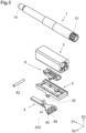
- the Fig. 3 shows an exploded view of a barrel 1 with locking sleeve 3 and the clamping device according to the invention consisting of a clamping lever 4, carrier 5 and clamping bar 6, which are connected to one another by a bolt 42 and are arranged in the housing 2, preferably in the upper housing 21. It is irrelevant to the invention whether the carrier 5 is designed as a separate part of the upper housing 21 or integrally therewith, since the function of the carrier 5 is to act as a stationary or housing-fixed receptacle for the clamping strip 6.
- the barrel 1 has various radial points at its rear end, distributed around the circumference "outside" projecting barrel lugs 15, which are designed to cooperate with barrel locking lugs 35 which project radially "inward” on the locking sleeve 3 in a shape-complementary manner.
- the barrel 1 can be fastened, for example in the manner of a bayonet lock, by inserting and turning it into the locking sleeve 3 in the axial direction, i.e. running direction 91.
- Other fastening options such as a screw-in thread, are also known in the prior art. It should be explicitly pointed out at this point that in a preferred variant the barrel 1 and the locking sleeve 3 are formed in one piece, i.e. integrally, with one another.
- Fig. 3 in conjunction with the Figs. 2 and 8 to 11 the way of assembling or inserting the barrel group, consisting of barrel 1 and locking sleeve 3, into the upper housing 21 can be derived.
- the upper housing 21 is not shown in the following illustrations, although the carrier 5 can be used as a receptacle fixed to the housing as a relative reference in this regard. This fact, which does not affect the invention, is disclosed in the simultaneous application EP19201455 explained in detail.
- FIG. 4a An exemplary embodiment of a carrier 5 is shown in a side view in Fig. 4a shown schematically and without housing 2 and particularly well in the perspective view in Fig. 4b visible. At least one elongated hole 55 is formed on the carrier 5 for receiving the bolt 42 in the transverse direction 92 - see also Fig. 8a .
- the embodiment of the carrier 5 shown in most of the figures shows a further optional feature with two tabs 59, which are formed on the underside of the carrier 5 and in which the elongated holes 55 are arranged.
- the designs of just one tab 59 or several tabs 59, as well as completely without a tab, are also conceivable, in which case the at least one elongated hole 55 leads directly through the carrier 5 as a through hole.
- the modification of the specific form of training of the carrier 5 can therefore be carried out relatively easily by a person skilled in the art based on the explanations given here, taking into account the geometric boundary conditions in the overall concept, in particular the overall height, of a firearm to be developed.
- the elongated hole 55 has a width 552, which essentially corresponds to a diameter D1 - 451 - of the clamping lever hole 45 and / or the strip hole 65, and whose length 551 is in the range of 1, 1 to 2.5 times, preferably 1.2 to 1.5 times the width 552. Due to the common bolt 42, the tensioning lever 4, the tensioning bar 6 and thus also the locking sleeve 3 can be tensioned downwards into the ready-to-fire position within limits in the vertical direction 93 or deflected upwards in the running direction 91 to release the locking sleeve 3.
- the relative position can be defined in particular by the length 551 of the elongated hole 55 and the relative position to the clamping lever hole 45 and/or the strip hole 65.
- the relative position and the insertion play can be influenced by the design and arrangement of the prism surface 321 of the locking sleeve 3 and the corresponding clamping surface 62 of the clamping bar 6. It should be mentioned at this point that the prism 32 can also be formed on the locking sleeve 3 in an analogous manner on the clamping bar 6, as will be explained below.
- the carrier 5 in the Figs. 2 and 4 also has a clamping bar receptacle 58, through which the clamping bar 6 protrudes through the carrier 5 when installed.
- the side guide surfaces 54 of the clamping bar receptacle 58 serve to guide the clamping bar in the vertical direction 93.
- the carrier 5 also has a rear stop 56 at its rear end, which serves to support the locking sleeve 3 relative to the upper housing 21 when ready to fire.
- this rear stop 56 mutatis mutandis, can also be formed directly, for example, on the upper housing 21.
- the clamping bar receptacle 58 can also have a limit and guide for the clamping bar 6 in the running direction 91 to the front, as shown in Fig. 2b is indicated schematically using a crossbar.
- FIG. 4b A special embodiment can be seen, according to which various guide grooves 57 are formed, which act as a guide for corresponding guide extensions 67 on the clamping bar 6 in vertical 93 and/or transverse 92 and/or Direction 93 serve. This becomes apparent when viewed together with the clamping bar 6 shown as an example Fig. 5 clearly.
- Fig. 5 Various exemplary embodiments of a tension bar 6 are shown.
- Fig. 5a the formation of the strip bore 65 in the transverse direction 92 is clearly visible.
- the Fig. 5b shows a one-piece design and the Fig. 5c a two-part clamping strip 6.
- the advantage of the one-piece variant is the high mechanical stability of the component.
- the advantage of the two-part variant can be, on the one hand, that the production of two identical, but oppositely arranged, partial clamping strips can be carried out very economically.
- clamping surfaces 62 are designed as prismatic guide surfaces, which cooperate with a prism 32 of the locking sleeve 3 (see e.g Fig. 7 ) are designed to complement form and function. These clamping surfaces 62 are oriented “inwards” towards the center plane of the weapon.
- the position and number of the strip bores 65 of the clamping strip 6 can also be optimized accordingly by the person skilled in the art, mutatis mutandis to the carrier 5 or the clamping lever 4 explained below, depending on the embodiment.
- the clamping surfaces 62 in the insertion area are beveled outwards in the running direction 91, as shown Figs. 5b and 5c can be seen, whereby the insertion of the prism 32 of the locking sleeve 3 can be simplified.
- These bevels 68 can be made from Fig. 5 and Fig. 9b can be seen very clearly and can be designed on one or both sides.
- the prism 32 is designed to point towards the rear stop surface 36 in the end region and to taper in the transverse direction 92. This measure can also make it easier to insert the locking sleeve 3.
- the tensioning lever 4 comprises an elongated handle 43, at least one tensioning lever bore 45, which, when installed, runs normal to the running direction 91 in the transverse direction 92 and coincides with the axis of rotation 452 of the tensioning bar 6.
- An extension is formed on the tensioning lever 4, which in the closed state has a front stop surface 37 pointing essentially upwards in the normal direction 93, compare Fig. 10b .
- This extension is referred to as cam 41 and can - as explained below - have several functions.
- a link-like clamping section 48 is formed on the clamping lever 4, preferably on the outside in the area of the clamping lever bore 45, which runs eccentrically to the clamping lever bore 45.
- the course of the clamping section 48 is chosen such that, in the ready-to-fire state, the clamping lever 4 biases the clamping bar 6, which is connected together with the bolt 42, in the vertical direction 93 by supporting the clamping section 48 on the carrier 5.
- the clamping section 48 and the cam 41 lie completely outside the path of movement of the locking sleeve 3 in the running direction 91, compare Fig. 2 .
- FIG. 8a is a side view
- Fig. 9a a bottom view of the clamping mechanism - without housing 2 - shown as an example.
- the Fig. 8b shows the detail Fig. 8a , in which it is clearly visible that when the clamping lever 4 is closed, the relative position of the clamping lever bore 45, or the aligned strip bore 65, lies within the elongated hole 55.
- Fig. 9c the clamping device is shown in the ready-to-fire state - without housing 2 - from the "front" in the running direction 91 to the rear.
- the applied clamping lever 4 causes the clamping bar 6 to be clamped downwards by means of the previously explained clamping sections 48 by pressing against the carrier 5.
- the interaction of the prismatic guide surfaces 321 and 62, as well as their formation parallel to the barrel bore 12 or the barrel core axis 11, can also be seen very well.
- Fig. 9c a longitudinal section along line IXc Fig. 9a shown, which shows the tension of the clamping section 48 on the carrier 5 very well, compare when looking together Fig. 2 .
- the Fig. 9c a longitudinal section along line IXc Fig. 9a shown, which shows the tension of the clamping section 48 on the carrier 5 very well, compare when looking together Fig. 2 .
- 9b shows a longitudinal section along line IXb, which reveals a section through the clamping device in the area of a clamping bar 6 somewhat closer to the weapon center plane.
- the strip bore 65 and the clamping lever bore 45 lie on the common axis of rotation 452, which lies within the elongated hole 55 of the carrier 5.
- Fig. 10a is a longitudinal section X through the weapon center plane Fig. 9c shown, in which the axial, i.e. in the running direction, fixation of the barrel 1, or the locking sleeve 3, is very clearly visible.
- the cam 41 formed on the handle 43 of the clamping lever 4 has a rear contact surface, hereinafter referred to as the front stop 47, which serves to support or rest on the front stop surface 37 of the locking sleeve 3.
- This detail Xb is in Fig. 10b shown enlarged and causes the locking sleeve 3 with a rear stop surface 36 to be biased against the carrier 5, or possibly directly the housing 2, in the ready-to-fire position, as shown in detail Xc in Fig. 10c is visible.
- FIG. 10b is a cross section along XII-XII Fig. 8a visible in the area of engagement of the cam 41.
- the barrel 1 should be spaced from the tip of the cam 41 by a gap 416 in the area of the flat 115 in the ready-to-fire position, see also Fig. 12b .
- the barrel 1 is stored in the locking sleeve 3 in a non-rotating manner, since when the clamping lever 4 is open, the cam 41 is disengaged from the flat 115 of the barrel 1 and this can be easily assembled. Due to the complementary shape of the flat 115 of the barrel 1, the cocking lever 4 can only be closed when the barrel 1 is aligned in a predetermined position in the locking sleeve 3. A type of “end position control” of the barrel 1 can thus be achieved in a simple manner.
- the gap 416 - if provided - is only a few hundredths of a millimeter, preferably 0.02 to 0.40 mm, particularly preferably from 0.10 to 0.20, as can also be seen from detail XIIb of Fig. 12a in Fig. 12b emerges well.
- the shape and number of cams 41 of the clamping lever 4 can be optimized. It has proven to be particularly advantageous to form two clamping sections 48, since in this way the local surface pressure on the carrier 5 can be reduced. This can be beneficial for the longevity of the clamping device. It is of course also possible to provide three or more clamping sections 48.
- FIG. 7 and Fig. 10a Another special embodiment is shown, according to which the front stop surface 37 of the locking sleeve 3 is formed on the underside of the locking sleeve 3 in a cam receptacle 371 provided for this purpose.
- the front stop surface 37 could also be provided on the end face of the locking sleeve 3, but this cam receptacle 371 can have the advantage that a reduced overall size or length of the clamping device can be achieved.
- the above description includes various exemplary embodiments for a locking sleeve 3 which, as in Fig. 7 and Fig. 11a clearly visible, preferably has a dovetail-like prism 32 to form the prism surfaces 321.
- the locking sleeve 3 can have at least one slot 38, preferably parallel to the running direction 91. This slot 38 is formed on at least one side of the locking sleeve 3, preferably starting from the weapon center plane, outwards over the entire length of the locking sleeve, and causes the tensioning of the clamping bar 6 to cause a tangential taper of the slot 38 when the clamping lever 4 is closed.
- the barrel 1 can be fixed in the locking sleeve 3 via a flat clamp in addition to being secured via the barrel lugs 15.
- This can be advantageous in terms of introducing the forces into the carrier 5 or the housing 2 of the firearm when the shot is fired. It is particularly advantageous if the slot 38 is not completely closed when clamping is carried out in order to prevent any possible distortion of the locking sleeve 3.
- the direction of action of the prismatic guide surfaces i.e. the clamping surface 62 of the clamping bar 6 and the prism surface 321 of the locking sleeve 3, is designed to be the opposite of the previous description. All previously described embodiments can be used mutatis mutandis.
- the design of a slotted locking sleeve 3 is conceivable, in such an arrangement it would lead to a reduction in the contact area between barrel 1 and locking sleeve 3 during clamping, which is why it should only be used in special arrangements.
- the locking sleeve and/or the barrel can be clamped effectively and with repeat accuracy in the ready-to-fire position, but can be replaced relatively easily if necessary.
- the barrel 1 can be removed from the housing 2 (not shown in detail) simply forwards when the cocking lever 4 is open. It is therefore possible to use a locking sleeve 3, matching the clamping bar 6, to accommodate different barrels 1 with, for example, different calibers, or, in the case of locking sleeves 3 formed integrally on the barrel 1, to exchange the corresponding barrels 1 with little manual effort and with repeatable accuracy to be positioned in housing 2.
- the invention is not limited to the exemplary embodiments shown and described, but can be modified and designed in various ways.
- the cross-sectional shapes shown of the housing parts mentioned, bolts, rails, recesses, etc. can be adapted to the specified basic data, and the lengths and positions with respect to the housing can also be easily adapted for the person skilled in the art given knowledge of the invention.
- equivalent designs are obvious given knowledge of the invention and can be easily carried out by a person skilled in the art.
- substantially means a deviation of up to 10% of the specified value, if physically possible, both downwards and upwards, otherwise only in the sensible direction, for degrees (angle and temperature) , and terms such as “parallel” or “normal” mean ⁇ 10°. When it comes to terms like “essentially constant” etc., what is meant is the technical deviation possibility that the expert uses as a basis and not the mathematical one.
- a “substantially L-shaped cross section” comprises two elongated surfaces, each of which merges into the end of the other surface at one end, and whose longitudinal extent is arranged at an angle of 45° to 120° to one another.
Landscapes
- Engineering & Computer Science (AREA)
- General Engineering & Computer Science (AREA)
- Clamps And Clips (AREA)
- Portable Nailing Machines And Staplers (AREA)
- Aiming, Guidance, Guns With A Light Source, Armor, Camouflage, And Targets (AREA)
- Mutual Connection Of Rods And Tubes (AREA)
Claims (15)
- Arme à feu, en particulier carabine, comprenant un boîtier supérieur (21) et un boîtier inférieur (22), le boîtier supérieur contenant au moins un canon (1) doté d'un axe de canon (11) et d'un manchon de verrouillage (3) pouvant être relié solidement au canon, un mécanisme de verrouillage, un mécanisme de percuteur, le cas échéant un mécanisme à gaz, le boîtier inférieur (22) contenant au moins une crosse (84), un chargeur (83) et un mécanisme de gâchette (82), le boîtier supérieur (21) et le boîtier inférieur (22) étant reliés entre eux à l'état monté prêt à tirer,
caractérisée en ce quesur le boîtier, notamment sur le boîtier supérieur (21), il est prévu un support (5) ou celui-ci est réalisé d'une seule pièce avec le boîtier supérieur, et en ce quele manchon de verrouillage (3), d'une part, et le support (5), le cas échéant directement le boîtier supérieur (21), d'autre part, sont reliés entre eux à l'aide d'une baguette de serrage (6), en ce quele manchon de verrouillage (3) et la baguette de serrage (6) présentent des surfaces de guidage (321, 62) prismatiques qui se correspondent entre elles et, à l'état monté prêt à tirer de l'arme, s'étendent parallèlement à l'axe de canon (11), en ce que la fixation du manchon de verrouillage (3) au boîtier supérieur (21) s'effectue au moyen d'un levier de serrage (4) qui peut être tourné dans le boîtier supérieur autour d'un axe de rotation (452) normal au plan médian de l'arme, entre deux positions extrêmes, à savoir la position prête à tirer et la position de démontage, et comprend au moins une partie de serrage (48) et un manche (43) et une came (41) réalisée sur le levier de serrage, en ce queun axe (42) est prévu pour relier la baguette de serrage (6) et le levier de serrage (4) le long de l'axe de rotation (452), respectivement à travers au moins un trou de baguette (65) et un trou de levier de serrage (45) réalisés normalement au plan médian de l'arme, en ce quedans la position prête à tirer, le manchon de verrouillage (3) est appliqué avec une surface d'arrêt arrière (36) contre le support (5) et est serré vers l'arrière par la came (41), dans le sens opposé au canon (91), et la partie de serrage (48) met la baguette de serrage (6) sous précontrainte dans la direction verticale (93), et en ce quedans la position démontée, la partie de serrage (48) et la came (41) se situent complètement à l'extérieur de la trajectoire de déplacement du manchon de verrouillage (3) en direction du canon (91). - Arme à feu selon la revendication 1, caractérisée en ce qu'au moins un trou oblong (55) est réalisé sur le support (5).
- Arme à feu selon la revendication 2, caractérisée en ce que le trou oblong (55) présente une largeur (552) qui correspond sensiblement à un diamètre D1 (451) du trou de levier de serrage (45) et/ou du trou de baguette (65), et en ce que sa longueur (551) est comprise dans la plage allant de 1,1 à 2,5 fois, de préférence de 1,2 à 1,5 fois la largeur (552).
- Arme à feu selon l'une des revendications précédentes, caractérisée en ce que le manchon de verrouillage (3) présente au moins une fente (38) réalisé parallèlement au sens du canon (91).
- Arme à feu selon l'une des revendications précédentes, caractérisée en ce que, sur un côté tourné vers la came (41) à l'état prêt à tirer, le canon (1) présente un méplat (115) ou un évidement de forme complémentaire à celle de la came (41).
- Arme à feu selon l'une des revendications précédentes, caractérisée en ce que la came (41) est réalisée sous une forme aplatie dans le sens transversal (92) et/ou dans le sens du canon (91).
- Arme à feu selon l'une des revendications 5 ou 6, caractérisée en ce que, dans la position prête à tirer, la came (41) et le méplat (115) sont séparés dans l'espace l'un de l'autre par un interstice (416), l'interstice (416) ayant de préférence une largeur allant de 0,02 mm à 0,4 mm, de manière particulièrement avantageuse de 0,10 mm à 0,20 mm.
- Arme à feu selon l'une des revendications précédentes, caractérisée en ce que le levier de serrage (4) présente au moins deux parties de serrage (48).
- Arme à feu selon l'une des revendications précédentes, caractérisée en ce que des tétons de guidage (67) latéraux sont réalisés sur la baguette de serrage (6), et des rainures de guidage (57) correspondantes sont réalisées sur le support (5).
- Arme à feu selon l'une des revendications précédentes, caractérisée en ce qu'un logement de came (371) est prévu sur le manchon de verrouillage (3) aux fins d'accueillir la came (41).
- Arme à feu selon l'une des revendications précédentes, caractérisée en ce que la baguette de serrage (6) est réalisée en plusieurs parties, de préférence en deux parties.
- Arme à feu selon l'une des revendications précédentes, caractérisée en ce que la baguette de serrage (6) présente au moins sur un côté des plans obliques (68) situés dans la zone d'introduction des surfaces de serrage (62).
- Arme à feu selon l'une des revendications précédentes, caractérisée en ce que sur le prisme (32), des rétrécissements sont réalisés latéralement, dans la partie d'extrémité, en étant orientés en direction de la surface d'arrêt arrière (36), et dans le sens transversal (92).
- Arme à feu selon l'une des revendications précédentes, caractérisée en ce que le manchon de verrouillage (3) est réalisé d'une seule pièce sur le canon (1) ou est relié de manière non détachable à celui-ci.
- Arme à feu selon l'une des revendications précédentes, caractérisée en ce que la surface de serrage (62) de la baguette de serrage (6) est réalisée de façon à être tournée vers l'extérieur dans le sens transversal (92), et la surface de prisme (321) correspondante du manchon de verrouillage est réalisée de manière à être tournée vers l'intérieur.
Applications Claiming Priority (2)
| Application Number | Priority Date | Filing Date | Title |
|---|---|---|---|
| EP19201455.3A EP3800434B1 (fr) | 2019-10-04 | 2019-10-04 | Pistolet, en particulier une carabine |
| PCT/EP2020/077111 WO2021063891A1 (fr) | 2019-10-04 | 2020-09-28 | Arme à feu dotée d'un dispositif de serrage de tube |
Publications (3)
| Publication Number | Publication Date |
|---|---|
| EP4038336A1 EP4038336A1 (fr) | 2022-08-10 |
| EP4038336B1 true EP4038336B1 (fr) | 2023-12-27 |
| EP4038336C0 EP4038336C0 (fr) | 2023-12-27 |
Family
ID=68158930
Family Applications (3)
| Application Number | Title | Priority Date | Filing Date |
|---|---|---|---|
| EP19201455.3A Active EP3800434B1 (fr) | 2019-10-04 | 2019-10-04 | Pistolet, en particulier une carabine |
| EP20775879.8A Active EP4038337B1 (fr) | 2019-10-04 | 2020-09-28 | Unité canon pour arme à feu |
| EP20775681.8A Active EP4038336B1 (fr) | 2019-10-04 | 2020-09-28 | Pistolet, en particulier une carabine |
Family Applications Before (2)
| Application Number | Title | Priority Date | Filing Date |
|---|---|---|---|
| EP19201455.3A Active EP3800434B1 (fr) | 2019-10-04 | 2019-10-04 | Pistolet, en particulier une carabine |
| EP20775879.8A Active EP4038337B1 (fr) | 2019-10-04 | 2020-09-28 | Unité canon pour arme à feu |
Country Status (5)
| Country | Link |
|---|---|
| US (3) | US11333460B2 (fr) |
| EP (3) | EP3800434B1 (fr) |
| CA (2) | CA3156638A1 (fr) |
| IL (2) | IL290580B2 (fr) |
| WO (2) | WO2021063876A1 (fr) |
Families Citing this family (5)
| Publication number | Priority date | Publication date | Assignee | Title |
|---|---|---|---|---|
| EP3800434B1 (fr) * | 2019-10-04 | 2023-11-01 | Glock Technology GmbH | Pistolet, en particulier une carabine |
| US11598600B2 (en) * | 2021-01-28 | 2023-03-07 | Robert W. Landies, III | Quick-change barrel for a firearm |
| EP4194795A1 (fr) | 2021-12-10 | 2023-06-14 | Glock Technology GmbH | Dispositif de réalisation d'une fixation secondaire d'un garde-main |
| EP4425088A1 (fr) | 2023-03-01 | 2024-09-04 | Glock Technology GmbH | Ensemble canon pour arme à feu |
| US12480729B1 (en) * | 2024-05-06 | 2025-11-25 | Matthew BUTCHER | Firearms, systems, and methods for quick connection of a barrel to a firearm |
Family Cites Families (40)
| Publication number | Priority date | Publication date | Assignee | Title |
|---|---|---|---|---|
| FR9820E (fr) * | 1908-01-29 | |||
| FR412523A (fr) * | 1909-05-03 | 1910-07-15 | Mimard Soc | Pistolet à répétition semi-automatique |
| DE303873C (fr) * | 1921-01-03 | |||
| GB268996A (en) * | 1926-05-28 | 1927-04-14 | William Beardmore & Company Lt | Improvements in or relating to mountain howitzers and the like |
| US2455608A (en) * | 1945-08-31 | 1948-12-07 | Orvar E Rosengren | Barrel lock |
| US2817174A (en) * | 1954-08-17 | 1957-12-24 | High Standard Mfg Corp | Take-down device for firearms |
| GB1200850A (en) * | 1967-07-31 | 1970-08-05 | Brev Aero Mechaniques S A | Improvements in/or relating to semi-automatic and automatic fire-arms |
| IL92039A0 (en) * | 1989-10-18 | 1990-07-12 | Israel State | Locking mechanism for machine gun barrel |
| US5410834A (en) * | 1993-08-05 | 1995-05-02 | Michael Edward Benton | Rifle with interchangeable barrel |
| DE19815261C2 (de) * | 1998-04-06 | 2000-03-30 | Manfred Orth | Zusammensetzbare Handfeuerwaffe |
| US6487805B1 (en) * | 2000-05-19 | 2002-12-03 | Armalite, Inc. | Firearm assembly |
| US6470617B1 (en) * | 2001-10-31 | 2002-10-29 | Thomas M. Gregory | Folding stock |
| FR2837275B1 (fr) * | 2002-03-14 | 2004-06-25 | Chapuis Armes | Carabine a canon amovible |
| EP1574806B1 (fr) * | 2004-03-11 | 2011-02-09 | Voere Holding GmbH | Fusil |
| WO2006086003A2 (fr) | 2004-07-27 | 2006-08-17 | Leitner-Wise Rifle Company, Inc. | Systeme de recepteur modulaire |
| DE102005037131B3 (de) * | 2005-08-06 | 2006-12-14 | Rheinmetall Waffe Munition Gmbh | Vorrichtung zum Verbinden und Verriegeln eines Verschlusses und/oder eines Laufes einer Waffe |
| DE102006022622A1 (de) | 2006-05-12 | 2007-11-15 | Rheinmetall Waffe Munition Gmbh | Funktionssteuerung insbesondere für das lineare Zuführen einer Munition in ein Waffenrohr |
| US7673553B2 (en) * | 2007-05-21 | 2010-03-09 | Karl Lippard | Barrel link for a semiautomatic weapon |
| US7841121B1 (en) | 2008-01-09 | 2010-11-30 | Browning | Takedown rifle |
| DE102009051416A1 (de) | 2008-10-30 | 2010-07-22 | Christian Scherpf | Langwaffe |
| US7823314B1 (en) * | 2008-12-02 | 2010-11-02 | Wheatley Craig A | Firearm with a detachable barrel and suppressed barrel assembly |
| US8087194B1 (en) * | 2009-03-24 | 2012-01-03 | Sturm, Ruger & Company, Inc. | Firearm barrel retaining system |
| DE102010000061A1 (de) | 2010-01-13 | 2011-07-14 | ContiTech Schlauch GmbH, 30165 | Schlauchförmiger Artikel, insbesondere Förderschlauch, mit progressiver Volumenzunahme und Verfahren zu dessen Herstellung |
| DE102010000617B4 (de) | 2010-03-03 | 2012-02-23 | Al Hail Holding Llc | Repetiergewehr mit austauschbarer Lauf-Verschlussgruppe |
| BR112012023713B1 (pt) | 2010-03-25 | 2021-05-18 | ArmWest, LLC | carregador, arma de fogo, e método |
| US9038525B2 (en) | 2011-01-14 | 2015-05-26 | ArmWest, LLC | Firearm |
| US8973483B2 (en) | 2010-03-25 | 2015-03-10 | Arm West, Llc | Gas regulator system |
| US9488423B2 (en) | 2011-01-14 | 2016-11-08 | Arm West, Llc | Firearm systems and methods |
| RU2637082C2 (ru) | 2011-01-14 | 2017-11-29 | АРМВЕСТ, ЭлЭлСи | Огнестрельное оружие с быстрой сменой ствола |
| DE202011100433U1 (de) * | 2011-05-07 | 2011-08-22 | Karl-Heinz Walz | Zerlegbares Gewehr |
| DE102011114686B3 (de) | 2011-10-04 | 2013-03-07 | J.P. Sauer & Sohn Gmbh | Handfeuerwaffe mit einer Laufaufnahme |
| WO2013090749A1 (fr) * | 2011-12-14 | 2013-06-20 | Sturm, Ruger & Company, Inc. | Système de logement de crosse pour arme à feu |
| DE202012101602U1 (de) | 2012-04-30 | 2012-06-12 | Liemke Gmbh & Co. Kg | Zerlegbare Schusswaffe |
| US9383154B2 (en) * | 2013-12-12 | 2016-07-05 | Ra Brands, L.L.C. | Gas vent for firearm |
| US20150308779A1 (en) | 2013-12-23 | 2015-10-29 | S. I. Defense, Inc. | Quick-release barrel firearm |
| AT14107U1 (de) | 2014-02-27 | 2015-04-15 | Strasser Herbert | Laufhalterung für eine Schusswaffe |
| SK288780B6 (sk) * | 2016-12-21 | 2020-10-02 | Michut Viktor | Uzamykací systém puzdra ručnej strelnej zbrane |
| US11137226B2 (en) * | 2019-02-21 | 2021-10-05 | Andrew Bennink | Multi-caliber weapon system and components |
| EP3800434B1 (fr) * | 2019-10-04 | 2023-11-01 | Glock Technology GmbH | Pistolet, en particulier une carabine |
| US11326853B2 (en) * | 2020-01-07 | 2022-05-10 | Brendon Zinsner | Free-floating rifle rail and barrel locking system(s)/assemblies |
-
2019
- 2019-10-04 EP EP19201455.3A patent/EP3800434B1/fr active Active
-
2020
- 2020-09-18 US US17/026,027 patent/US11333460B2/en active Active
- 2020-09-27 IL IL290580A patent/IL290580B2/en unknown
- 2020-09-28 CA CA3156638A patent/CA3156638A1/fr active Pending
- 2020-09-28 IL IL290874A patent/IL290874B2/en unknown
- 2020-09-28 WO PCT/EP2020/077084 patent/WO2021063876A1/fr not_active Ceased
- 2020-09-28 US US17/754,449 patent/US12092413B2/en active Active
- 2020-09-28 CA CA3152033A patent/CA3152033A1/fr active Pending
- 2020-09-28 WO PCT/EP2020/077111 patent/WO2021063891A1/fr not_active Ceased
- 2020-09-28 EP EP20775879.8A patent/EP4038337B1/fr active Active
- 2020-09-28 EP EP20775681.8A patent/EP4038336B1/fr active Active
- 2020-09-28 US US17/753,945 patent/US11841201B2/en active Active
Also Published As
| Publication number | Publication date |
|---|---|
| CA3156638A1 (fr) | 2021-04-08 |
| IL290874B2 (en) | 2025-09-01 |
| IL290580B2 (en) | 2025-05-01 |
| US12092413B2 (en) | 2024-09-17 |
| WO2021063876A1 (fr) | 2021-04-08 |
| US20210164750A1 (en) | 2021-06-03 |
| IL290580A (en) | 2022-04-01 |
| US20220341695A1 (en) | 2022-10-27 |
| EP4038337A1 (fr) | 2022-08-10 |
| EP3800434B1 (fr) | 2023-11-01 |
| IL290874B1 (en) | 2025-05-01 |
| BR112022003017A2 (pt) | 2022-06-28 |
| EP4038337C0 (fr) | 2023-12-27 |
| EP4038336A1 (fr) | 2022-08-10 |
| EP4038337B1 (fr) | 2023-12-27 |
| US11333460B2 (en) | 2022-05-17 |
| IL290874A (en) | 2022-04-01 |
| BR112022003239A2 (pt) | 2022-07-19 |
| CA3152033A1 (fr) | 2021-04-08 |
| EP3800434C0 (fr) | 2023-11-01 |
| EP3800434A1 (fr) | 2021-04-07 |
| US11841201B2 (en) | 2023-12-12 |
| WO2021063891A1 (fr) | 2021-04-08 |
| EP4038336C0 (fr) | 2023-12-27 |
| IL290580B1 (en) | 2025-01-01 |
| US20220341696A1 (en) | 2022-10-27 |
Similar Documents
| Publication | Publication Date | Title |
|---|---|---|
| EP4038336B1 (fr) | Pistolet, en particulier une carabine | |
| DE3522027C2 (fr) | ||
| DE102018132756B4 (de) | Umrüstsatz für eine Kurzwaffe | |
| WO1990010841A2 (fr) | Fusil, notamment fusil de chasse, a canon echangeable, et systeme modulaire pour ce fusil | |
| EP4038332B1 (fr) | Culasse pour une arme à feu | |
| DE20319451U1 (de) | Schußwaffe | |
| WO2001063198A1 (fr) | Arme de poing a feu a repetition avec blocage de fermeture liberable | |
| DE9304489U1 (de) | Sturmgewehr | |
| EP1924815B1 (fr) | Bloc cylindrique pour la recuperation de gaz et arme de poing | |
| WO2021204565A1 (fr) | Dispositif de fixation pour fixer des accessoires à une arme à feu portative | |
| DE69500286T2 (de) | Befestigungsvorrichtung eines Waffenlaufs | |
| EP4130640B1 (fr) | Tête de culasse pour une arme à feu | |
| EP4177562B1 (fr) | Arme de chasse ou de sport ayant un système de chargeur amélioré | |
| EP4246082B1 (fr) | Tête de coulasse d'un arme de chasse ou de sport | |
| EP4194796B1 (fr) | Fusil doté d'un dispositif de sécurité de fermeture | |
| DE102005036251B3 (de) | Schnellfeuergewehr und Umrüstverfahren | |
| EP4194795A1 (fr) | Dispositif de réalisation d'une fixation secondaire d'un garde-main | |
| EP4038333B1 (fr) | Carabine dotée d'une poignée de charge | |
| EP3973244B1 (fr) | Boîtier supérieur pour une arme à feu | |
| EP1559984B1 (fr) | Arme à feu de poing | |
| DE3204823C2 (de) | Einstecklauf zum Verschießen kleinkalibriger Geschosse | |
| EP0115034A1 (fr) | Fusil à canon remplaçable | |
| EP3825640B1 (fr) | Pistolet | |
| DE102007005142A1 (de) | Anschlussstück | |
| EP4230950A1 (fr) | Culasse pour fusil à répétition |
Legal Events
| Date | Code | Title | Description |
|---|---|---|---|
| STAA | Information on the status of an ep patent application or granted ep patent |
Free format text: STATUS: UNKNOWN |
|
| STAA | Information on the status of an ep patent application or granted ep patent |
Free format text: STATUS: THE INTERNATIONAL PUBLICATION HAS BEEN MADE |
|
| PUAI | Public reference made under article 153(3) epc to a published international application that has entered the european phase |
Free format text: ORIGINAL CODE: 0009012 |
|
| STAA | Information on the status of an ep patent application or granted ep patent |
Free format text: STATUS: REQUEST FOR EXAMINATION WAS MADE |
|
| 17P | Request for examination filed |
Effective date: 20220404 |
|
| AK | Designated contracting states |
Kind code of ref document: A1 Designated state(s): AL AT BE BG CH CY CZ DE DK EE ES FI FR GB GR HR HU IE IS IT LI LT LU LV MC MK MT NL NO PL PT RO RS SE SI SK SM TR |
|
| DAV | Request for validation of the european patent (deleted) | ||
| DAX | Request for extension of the european patent (deleted) | ||
| GRAP | Despatch of communication of intention to grant a patent |
Free format text: ORIGINAL CODE: EPIDOSNIGR1 |
|
| STAA | Information on the status of an ep patent application or granted ep patent |
Free format text: STATUS: GRANT OF PATENT IS INTENDED |
|
| INTG | Intention to grant announced |
Effective date: 20230927 |
|
| GRAS | Grant fee paid |
Free format text: ORIGINAL CODE: EPIDOSNIGR3 |
|
| GRAA | (expected) grant |
Free format text: ORIGINAL CODE: 0009210 |
|
| STAA | Information on the status of an ep patent application or granted ep patent |
Free format text: STATUS: THE PATENT HAS BEEN GRANTED |
|
| AK | Designated contracting states |
Kind code of ref document: B1 Designated state(s): AL AT BE BG CH CY CZ DE DK EE ES FI FR GB GR HR HU IE IS IT LI LT LU LV MC MK MT NL NO PL PT RO RS SE SI SK SM TR |
|
| REG | Reference to a national code |
Ref country code: GB Ref legal event code: FG4D Free format text: NOT ENGLISH |
|
| REG | Reference to a national code |
Ref country code: CH Ref legal event code: EP |
|
| RIN2 | Information on inventor provided after grant (corrected) |
Inventor name: BILGERI, ELMAR Inventor name: WUTTE, ANDREAS |
|
| REG | Reference to a national code |
Ref country code: DE Ref legal event code: R096 Ref document number: 502020006538 Country of ref document: DE |
|
| REG | Reference to a national code |
Ref country code: IE Ref legal event code: FG4D Free format text: LANGUAGE OF EP DOCUMENT: GERMAN |
|
| U01 | Request for unitary effect filed |
Effective date: 20240116 |
|
| U07 | Unitary effect registered |
Designated state(s): AT BE BG DE DK EE FI FR IT LT LU LV MT NL PT SE SI Effective date: 20240125 |
|
| PG25 | Lapsed in a contracting state [announced via postgrant information from national office to epo] |
Ref country code: GR Free format text: LAPSE BECAUSE OF FAILURE TO SUBMIT A TRANSLATION OF THE DESCRIPTION OR TO PAY THE FEE WITHIN THE PRESCRIBED TIME-LIMIT Effective date: 20240328 |
|
| PG25 | Lapsed in a contracting state [announced via postgrant information from national office to epo] |
Ref country code: ES Free format text: LAPSE BECAUSE OF FAILURE TO SUBMIT A TRANSLATION OF THE DESCRIPTION OR TO PAY THE FEE WITHIN THE PRESCRIBED TIME-LIMIT Effective date: 20231227 |
|
| PG25 | Lapsed in a contracting state [announced via postgrant information from national office to epo] |
Ref country code: GR Free format text: LAPSE BECAUSE OF FAILURE TO SUBMIT A TRANSLATION OF THE DESCRIPTION OR TO PAY THE FEE WITHIN THE PRESCRIBED TIME-LIMIT Effective date: 20240328 Ref country code: ES Free format text: LAPSE BECAUSE OF FAILURE TO SUBMIT A TRANSLATION OF THE DESCRIPTION OR TO PAY THE FEE WITHIN THE PRESCRIBED TIME-LIMIT Effective date: 20231227 |
|
| PG25 | Lapsed in a contracting state [announced via postgrant information from national office to epo] |
Ref country code: RS Free format text: LAPSE BECAUSE OF FAILURE TO SUBMIT A TRANSLATION OF THE DESCRIPTION OR TO PAY THE FEE WITHIN THE PRESCRIBED TIME-LIMIT Effective date: 20231227 Ref country code: NO Free format text: LAPSE BECAUSE OF FAILURE TO SUBMIT A TRANSLATION OF THE DESCRIPTION OR TO PAY THE FEE WITHIN THE PRESCRIBED TIME-LIMIT Effective date: 20240327 Ref country code: HR Free format text: LAPSE BECAUSE OF FAILURE TO SUBMIT A TRANSLATION OF THE DESCRIPTION OR TO PAY THE FEE WITHIN THE PRESCRIBED TIME-LIMIT Effective date: 20231227 |
|
| PG25 | Lapsed in a contracting state [announced via postgrant information from national office to epo] |
Ref country code: IS Free format text: LAPSE BECAUSE OF FAILURE TO SUBMIT A TRANSLATION OF THE DESCRIPTION OR TO PAY THE FEE WITHIN THE PRESCRIBED TIME-LIMIT Effective date: 20240427 |
|
| PG25 | Lapsed in a contracting state [announced via postgrant information from national office to epo] |
Ref country code: SK Free format text: LAPSE BECAUSE OF FAILURE TO SUBMIT A TRANSLATION OF THE DESCRIPTION OR TO PAY THE FEE WITHIN THE PRESCRIBED TIME-LIMIT Effective date: 20231227 |
|
| PG25 | Lapsed in a contracting state [announced via postgrant information from national office to epo] |
Ref country code: SM Free format text: LAPSE BECAUSE OF FAILURE TO SUBMIT A TRANSLATION OF THE DESCRIPTION OR TO PAY THE FEE WITHIN THE PRESCRIBED TIME-LIMIT Effective date: 20231227 Ref country code: SK Free format text: LAPSE BECAUSE OF FAILURE TO SUBMIT A TRANSLATION OF THE DESCRIPTION OR TO PAY THE FEE WITHIN THE PRESCRIBED TIME-LIMIT Effective date: 20231227 Ref country code: RO Free format text: LAPSE BECAUSE OF FAILURE TO SUBMIT A TRANSLATION OF THE DESCRIPTION OR TO PAY THE FEE WITHIN THE PRESCRIBED TIME-LIMIT Effective date: 20231227 Ref country code: IS Free format text: LAPSE BECAUSE OF FAILURE TO SUBMIT A TRANSLATION OF THE DESCRIPTION OR TO PAY THE FEE WITHIN THE PRESCRIBED TIME-LIMIT Effective date: 20240427 |
|
| PG25 | Lapsed in a contracting state [announced via postgrant information from national office to epo] |
Ref country code: PL Free format text: LAPSE BECAUSE OF FAILURE TO SUBMIT A TRANSLATION OF THE DESCRIPTION OR TO PAY THE FEE WITHIN THE PRESCRIBED TIME-LIMIT Effective date: 20231227 |
|
| PG25 | Lapsed in a contracting state [announced via postgrant information from national office to epo] |
Ref country code: PL Free format text: LAPSE BECAUSE OF FAILURE TO SUBMIT A TRANSLATION OF THE DESCRIPTION OR TO PAY THE FEE WITHIN THE PRESCRIBED TIME-LIMIT Effective date: 20231227 |
|
| REG | Reference to a national code |
Ref country code: DE Ref legal event code: R097 Ref document number: 502020006538 Country of ref document: DE |
|
| U20 | Renewal fee for the european patent with unitary effect paid |
Year of fee payment: 5 Effective date: 20240918 |
|
| PLBE | No opposition filed within time limit |
Free format text: ORIGINAL CODE: 0009261 |
|
| STAA | Information on the status of an ep patent application or granted ep patent |
Free format text: STATUS: NO OPPOSITION FILED WITHIN TIME LIMIT |
|
| 26N | No opposition filed |
Effective date: 20240930 |
|
| PG25 | Lapsed in a contracting state [announced via postgrant information from national office to epo] |
Ref country code: MC Free format text: LAPSE BECAUSE OF FAILURE TO SUBMIT A TRANSLATION OF THE DESCRIPTION OR TO PAY THE FEE WITHIN THE PRESCRIBED TIME-LIMIT Effective date: 20231227 |
|
| REG | Reference to a national code |
Ref country code: CH Ref legal event code: PL |
|
| PG25 | Lapsed in a contracting state [announced via postgrant information from national office to epo] |
Ref country code: CH Free format text: LAPSE BECAUSE OF NON-PAYMENT OF DUE FEES Effective date: 20240930 |
|
| PG25 | Lapsed in a contracting state [announced via postgrant information from national office to epo] |
Ref country code: IE Free format text: LAPSE BECAUSE OF NON-PAYMENT OF DUE FEES Effective date: 20240928 |
|
| PGFP | Annual fee paid to national office [announced via postgrant information from national office to epo] |
Ref country code: TR Payment date: 20250922 Year of fee payment: 6 |
|
| PGFP | Annual fee paid to national office [announced via postgrant information from national office to epo] |
Ref country code: GB Payment date: 20250917 Year of fee payment: 6 |
|
| PGFP | Annual fee paid to national office [announced via postgrant information from national office to epo] |
Ref country code: CZ Payment date: 20250917 Year of fee payment: 6 |
|
| U20 | Renewal fee for the european patent with unitary effect paid |
Year of fee payment: 6 Effective date: 20250915 |
|
| PG25 | Lapsed in a contracting state [announced via postgrant information from national office to epo] |
Ref country code: CY Free format text: LAPSE BECAUSE OF FAILURE TO SUBMIT A TRANSLATION OF THE DESCRIPTION OR TO PAY THE FEE WITHIN THE PRESCRIBED TIME-LIMIT; INVALID AB INITIO Effective date: 20200928 |
|
| PG25 | Lapsed in a contracting state [announced via postgrant information from national office to epo] |
Ref country code: HU Free format text: LAPSE BECAUSE OF FAILURE TO SUBMIT A TRANSLATION OF THE DESCRIPTION OR TO PAY THE FEE WITHIN THE PRESCRIBED TIME-LIMIT; INVALID AB INITIO Effective date: 20200928 |